Leaderboard


Popular Content
Showing content with the highest reputation on 11/02/2020 in Posts
-
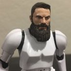
For my first foray into the TK world, 6 of us did an amazing patrol Halloween night in downtown Culver City. Keep the area Rebel free and handed out 2500 pieces of candy. you can see a video of the patrol on my FB page (KC Grim) and on the SCG FB page. Had a ton of fun and only discovered one pinch point that I have already taken care of. Looking forward to officially TK trooping. Was a bit less comfortable than my Scout, but definitely doable.
 4 points
 -
This is amazing! This FISD staff are incredible.2 points
-
Well, my plans to closely document my son's build did not go as planned. After school started back I found myself trying to squeeze in a few minutes here and a few there to get his kit done. He was also back to FSU, so we were only able to work on fitment when he was home on the occasional weekend. That being said, I did manage to get him finished up in time to submit before our Halloween troop. We're still have a few adjustments to make, but he was looking sharp this weekend. We hope to have his TK ID this week.2 points
-
D.O. Staff standing by for any and all questions! LET'S DO THIS!2 points
-
This is excellent! SO happy I'm finishing up my first TK now. With luck I'll get my applications sorted soon. Sent from my Imperial Communicator2 points
-
Awesome guys @Sly11, @gmrhodes13 !!!2 points
-
WARNING: The following content may be controversial! DISCLAIMER: These are my opinions from years of experience, pure and simple. Over the years I have noticed many future Troopers doing an OT (Original Trilogy) TK ask about return edges before, during (and after) their build... If this is a subject that you are curious about, grab a cup of coffee or a tall glass of frosty blue milk (this is a long post, lol) and read on.... QUESTION: "What are they, what do they do, and should I leave them, trim them down some or remove them"? ANSWER: Return edges are part of the molding process and provide strength in certain areas on the edges of your armor. They also provide a heftier look to some pieces. To help you decide whether or not to keep them is why I started this thread. Here I will attempt to go into a few details about them. Know in advance that as mentioned I personally am NOT a fan of them in many areas for several reasons (listed below). Some people love them and some may disagree with my opinions... many of you may trooped for years with no problems which is AWESOME, but many folks have had issues and questions. 1. In most areas they are not screen accurate- In looking at the screen caps and film used armor photos below you will notice their scarcity. 2. They can (and in many cases will) get very uncomfortable- Many folks like the "thicker" look it gives their armor, but they can cut into you, especially in the area where your arm bends ("armor bite") and the groin area (chafing). As Troopers we do a lot of walking and arm bending carrying a weapon, so keep this in mind. 3. If aiming for higher levels they can cause fitting issues- Examples: A. If you leave them on your forearm openings and glue on the cover strips, they will need to be completely removed at the wrists for Centurion level, making the opening too wide. This can lead to you having to remove the cover strips, reduce the sides of the forearms and re-attach the strips. Quite a pain in the posterior plate to say the least. *** See EXAMPLE 1 below. B. If they are overly thick on the bottoms of your shoulder bells, they can prevent them from lying snug against the biceps. 4. They can cause splits/cracks- Especially on some armor areas. ABS is designed to flex, and in some cases a small amount of return edge is fine, but too much can cause stress on those areas. *** See EXAMPLE 2 below Over time that stress will take it's toll somewhere, and that is usually the return edge. Anovos armor is especially prone to this on the sides of the chest/back plates and neck openings. I suggest shimming these on the rear with ABS strips and E-6000 to prevent it. Let's start with the chest plate: Note how the ones below (including the back plate) have either no or minimal edges with no cracks or splits. Now here is a screen used one with a pretty prominent edge, Notice the stress crack. Now, onto the ab/kidney/back plate: To keep them in line and prevent them from overlapping, it is suggested that you LEAVE a fair amount of the edges on the top/bottoms of the kidney and bottom of the back plate, especially if using the "classic" strapping method. Yes, these can split/crack as well but not normally. Shoulder Bells Trimming off the entire edge on the bottoms is not only screen accurate (first two photos), it allows them to rest close to the bicep (bottom photo). Third photo shows "suggested" trim lines (red) of an untrimmed bicep. My recommendation is the blue line. Biceps/forearms For sheer comfort and a sleeker look, I recommend removing ALL of the top and bottom edges before fitting/gluing them. First, no one sees the tops (covered by the shoulder bell) and the bottoms can cut into your arms (armor bite). Suggested cut lines in red. Again, if you do get armor bite you will have to take them both completely apart, remove the edge and re-fit. Better to think ahead. Some (myself included) like to leave a bit of the return edge on the outside of the top of the forearm for a thicker look. However, I highly suggest removing all from the inside part (the "scoop") where your arm bends. Again, an armor bite issue. This should also be done BEFORE final fitting. Here are some screen used examples: For level 3 (Centurion) all of the return edge on the wrist opening must be removed, including the area inside the "hump" as seen below: Posterior (butt) plate: Again, it is suggested that you leave some of the return edge on the top (and bottom in most cases) to keep it from riding under/over the kidney. Now, the BOTTOM of the posterior plate is where we often find splitting issues. Should you leave some return edge? Sure! BUT(T), when trimming the corners, (see below) be SURE not to give it a sharp angle... this is where the trouble usually starts. Instead, give it a slightly rounded angle (as shown in green). Thigh tops The tops of the thighs are where we see a lot of questions. I recommend removing all the return edges from the entire upper parts, and here is why: As mentioned above, you will be doing a lot of walking. If you have the edges (or at least a large portion of them) intact, the friction and inside facing angles can really chafe the heck out of you, especially on the inside of the groin area. (Ouch). If there are sharp edges/points on the tops (below) these will poke into you. When trimming these, just follow the existing line. Also, if you do your final fitting, glue everything together and find this out afterward, you will have to take the entire thing apart, remove the return edges, trim down the sides and then re-build/glue them back together. The reason is that afterward the opening will be entirely too large and you will have a giant gap all the way around. Not a good look. Easier to do it beforehand, trust me. As seen below, there were no return edges (or at least minimal ones) used in the films. Sniper knee plate The bottom of this piece is an area often not trimmed enough. To allow it to sit flat (or very close to flat) against the top of the calf enough for the glue to adhere properly I suggest removing most if not all of the bottom edge. Note how in the first and third photos how the sniper knee is parallel to the front of the calf. Last up, a photo that best illustrates my point about return edges and how they were not really present in many places on ANH armor. *** Example 1. of what happens when you have to reduce the return edge(s) after attaching cover strips. NOTE: For the example below I am using an ATA bicep (first 3 photos). Be aware that ATA makes the "suggested" cut line on their return edges pretty slim (a GREAT thing in my opinion). As seen on the armor in the 4th photo, if followed, the "suggested" cut line makes the return edges much wider (red line). Top view Bottom view For the purposes of this tutorial, we will assume that the ATA has those wider suggested return edges. Okay, let's say you really like the thicker look the return edges give your armor, so you left them pretty wide during fitting and then glued on the cover strips. Enough to get your arm through with a little extra room. Should be good to go, correct? BUT, you find that after having your arm bent for a while they cut into you (armor bite), so you find you have to reduce or remove most or all of it. No biggie, right? Just break out the Lexan scissors or Dremel and cut away, leaving the cover strips attached. Easy! So you remove it and then you run into the fact that the opening is now enormous. This is not a good look, and can result in the piece(s) jangling around and not being approvable at higher levels (or even Basic depending on your GML). What I am getting at with the above info. is that if you decide to remove them, it's better to do it before final fitting/gluing. Side note: Many biceps have an unusual shape at the tops (in red, below) normally located on the inside. This can be completely removed. Doing this will not affect approval at any level, and is screen accurate. It sits under the shoulder bell so no one sees it anyway! Screen used bicep USELESS TRIVIA: Many have asked about the "thumbprint" that many armorers have on the left bicep (screen used example below). Some think it is so you can tell them apart, but I was speaking with Brian Muir a few years ago (he sculpted the original armor used in ANH) and asked him about it: "To be honest, I have no idea... it was not in my original sculpt, and must have been a mistake in casting". There you have it. *** EXAMPLE 2: What causes cracks/splits: ABS bends pretty well, just as it's designed to. BUT, when there are return edges involved that changes the game. For the below example I used a 2 inch wide strip of ABS with a 1/2 inch "return edge". Looks pretty solid, right? That's because the edge provides stability. Now I am bending it up/in to simulate use over time. (More than it normally gets bent in many cases, but only to prove a point). That stress has got to go somewhere, and it's the return edge that takes it all and gives way, again causing cracks/splits. The red arrow shows a weak area where the stress in concentrated and cracks can form. Even if trimmed off afterward that area will be prone to splitting, so a small shim behind it is suggested. To sum it up, return edges are not meant to bend a lot. I suggest inspecting your armor occasionally to spot any existing/potential cracks/splits so that you can catch them before they get worse. I hope this helps answer any basic questions you may have, and always feel free to ask more detailed ones here or offer differing opinions.1 point
-
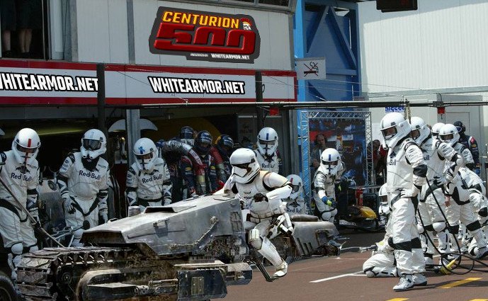
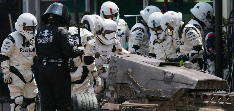
Hot off the heals of our Victory1000 celebrations, FISD are proud to bring you our next target event. We are fast approaching another milestone and another chance to celebrate victory as we hit 500 Centurions approved. This miles stone will also come with another special Centurion only piece of merch for the first 500, in the form of a pin to match the Expert Infantry exclusive. Our very own gmrhodes13 (Glen) has outdone himself yet again and put together the perfect introduction for this milestone event so without further adieu, FISD brings you. THERE ARE ONLY 7 POSITIONS ON THE GRID, SO IT'S TIME TO HIT THE ACCELERATOR, SHIFT INTO HYPER-DRIVE AND HELP US BLAST ACROSS THE LINE! Now that we have reached 1000 Expert Infantry, It's time to once again become part of FISD history and enter the "Centurion 500" We are aiming to have 500 approved Centurions by the end of the year. We only have 7 to go, so in order to reach that goal we are asking that you read over the CRLs for your particular armor, (this thread will help) make any necessary adjustments and post up your submission! Photo Checklists - Link here Apply here Questions: 1. Not sure if I have what it takes to reach Centurion- You don't know until you try, and you have not only the D.O. staff but an entire Detachment to help! 2. I need some repairs/fixes first- This is why we are here! We honestly want you to succeed and are here to help in any way we can. 3. I am happy with the way my armor looks, so why bother?- It not only makes you look more screen accurate, it instills a sense of pride and "esprit de corps"! 4. What if I don't make it? No worries, we will provide detailed suggestions on how to reach your goal! Benefits: 1 Bragging rights for being one of the "Original 500" 2. You get a cool badge under your name here on the FISD (full forum version) 3. Access to Exclusive Centurion500 pin for those in the original 500. 4. Certificate for your accomplishment. 5. You will have a more screen accurate looking set of armor. Now that the entire Staff and those who have reached Levels 2 and 3 are here to help in any way we can, you are more than welcome (and encouraged) to ask any and all questions you may have here on this thread, or contact Joseph, Sha Sha or Mario. Let's get up to speed, push that throttle and prepare for lightspeed, you can do it troopers Your Deployment Officers, Staff and the whole detachment crew are standing by ready to assist If you'd like to show your support on FB here is the link to the Centurion500 profile frame www.facebook.com/profilepicframes/?selected_overlay_id=331320651285964

 1 point
 -
Greetings to everyone! I'm Sven from western Germany, Located in the "Ruhrpott", 31 Years old and finally owner of a RS Propmasters ANH Stunt TK. I finally fullfilled my wish to get hands on my own ANH Stunt Stormtrooper Armor. After I read several threads in the german garrison forum and afterwards ordered my fully commission TK from RS Propmasters, I'm forced to use the glorious informations from here. Reaoson for commission: not mush space for building up a complete armour (definitely a mistake, i would have made that) but my time is very limited, last year my son was born so he needs and deserves mich of my time. My hope is to troop with the german garrison when if the Covid-19 is beaten up... Maybe next year?! My "problem" is, that I'm very slim and tall, horribly slim to be honest: waist 85cm only and 183cm tall, could call me Slenderman! After putting on my TK Armour I noticed that the Kidney and Abd plate are overlapping several centimeters. I tried padding, but that would need so much of it, that it would look ridiculous. Im curious if that's ok or am I forced to cut the kidney on both sides? And if it has to be cut down, does this part need a return edge to get approved? Next thing: it seems like I have very long arms. Does this fit properly like that or what should I adjust? I habe to get the Biceps fixed to the shoulders cause they always slide down. And as it seems have to renew the strapping between biceps and forearm, it's a bit too short, there would be a massive gap between my handguards and the forearm armour. In Hope it's not to much technical questioning for this part of the forum. Finally the first photo of me in full armour1 point
-
Should be able to finish TKSpartans list by tomorrow!1 point
-
Here is what I have currently which, more or less, follows the angle of the front of the face piece.1 point
-
One more option for armor is Imperial Surplus https://imperialsurplus.com/product/first-order-stormtrooper/ Very happy to see this available (again).1 point
-
Welcome to the Detachment! Persistence in both your ambition to become a member of the 501st as well as throughout your build process has definitely paid off. Looking good Trooper!1 point
-
This is very exciting! "The March to 1000" was a lot of fun so I'm really looking forward to the "Centurion 500"!1 point
-
Looks much better, Shawn! One last request: could you please post a photo of a more head-on angle of your hovi tips? They look like they're pointed down quite a bit but it could also just be the angle you took your helmet pics. Yours: Reference:1 point
-
Thank you, Mario!1 point
-
Hey! you both looks great !! congratulations1 point
-
OP (MV) Post #32: Thermal Detonator Part 2 In my previous post (Part 1) I began my thermal detonator, and in this post I will continue with painting the tube and installing the control panel and end caps. But first, a little twist to start us off. As I began to look ahead towards altering my universal-sized clips to fit my 2-inch (50.8mm inner diameter) tube I felt the need to study screen-captures of all the TDs in ANH. Essentially I wanted to get a good sense of TD height placement relative to the belt, as well as gauge the angle at which the control panel points. While the FISD Gallery has excellent content, for my purposes the 1,059 screen images captured chronologically by Jeklynhyde in this post provided the easiest access. I sifted through that image bank, along with Gallery albums from @Darth Aloha and @Locitus and all 119 pages (21,248 images in case you're wondering) of 4K ANH caps from starwarsscreencaps (hereafter referred to as SWSC) and saved 129 images to this google drive folder (yeah, I went a bit Han-boring-conversation-anyway heavy) to compile into a RogueTrooper-frown-like thermal detonator collages shown at the top of this post. Though my initial intention had been to capture detonator-belt height alignment, I also included images which documented other details of TDs, such as mounting clips and screw placement. The photos shown at the top of this post are actually downsized versions semi-optimized for viewing at 1,000 x 750px on the FISD web-platform, but if you click on the images they should link to the full 2,000 x 1,500px versions which contain un-scaled captures from the 1,920 x 1,080 (really 1,920 x 817 at the 2.35:1 anamorphic screen ratio) source imagery from @Jeklynhyde. The un-scaled snips from SWSC are from their 3,840 x 1,600 native resolution. Jeklyn was also kind enough to provide me with additional screen grabs upon request, on multiple occasions! Of the 129 images kept, 27 came from SWSC and 18 came from the FISD Gallery; none of the Gallery images were used in my final compilations. I used a transparent background on the images so that they would display cleanly in Tapatalk and in the current and future color schemes of the whitearmor site, and every individual image snippet is ordered chronologically by appearance in the film horizontally across the two master compilation images. The eight images below are quarter slices of the two master comp images, should any of you want to view the full-resolution content in-line/thread. HERE IS A LINK to my google drive folder which contains all eight of the above quadrant photos, as well as the master compilations. Contained in the master folder of copies of the versions of the images with three background colors—transparent, FISD gray, and white. While sifting through the 22,000+ ANH captures I tagged some for future projects, such as compilations of other parts of ANH TKs. The sniper plate, knee ammo belt, shoulder bridges, drop box alignment, and mobility cuts immediately come to mind. I've already developed a magnifying bubble overlay system that I'm going to use, and perhaps the images might be a helpful addition to some of the "Specific Parts" sections of the Gallery. In case anybody is interested, below is a Google drive folder which contains every SWSC capture I retained from the original image bank. These 3,688 images include every instance in which even part of a TK (and TD Sandie) are visible, whether it be part of a helmet peeking out from behind another character, a knee-pack barely above the trash compactor water, or Luke wearing TK-421's belt. Those with an extremely keen eye might notice some sequenced images missing, and that's because 45 images in the SWSC bank were repeat frames (which I excluded), likely due to capture, upload, or database errors. EVERY ANH TK from SWSC (3,688 images) Staring at all those images for hours (days) is now making me want to get a UK/metric-sized TD, but for now I'll have to make due without (anybody have a spare?). Seems I'm getting caught up in the finer details like our good friend @CableGuy. Lest any readers get bogged down in the next three sections (Painting, Re-Squaring, ABS Installation) of this post, I'd like to draw particular attention to the last section at the end, related to modifying my belt clips. I have diagrammed a couple options and would LOVE some feedback. Painting In continuing with Tony's documented paint process, I taped up my tube in order to cover a space the size of the control panel. To perfectly center the panel, I took the total length of my tube (7.25 inches or 184.15mm) and subtracted the width of my control panel (122mm), which left me with roughly 62mm. Since this represented the total remainder width, I divided it by two, and thus my guide marks were made 31mm from each end. Keep in mind that, if you're following my posts as a guide, your measurements will vary based on the figures you cut your tube and panel to. I then used my actual finished panel as a straightedge to guide my ballpoint PEN as I traced the border. I emphasize using a PEN because, even though I know pencil wipes off ABS, I wanted to avoid marking the edges of my control panel. This would have likely happened with pencil lead, but did not occur with my ballpoint pen. Do not worry about getting a perfectly straight line since the actual cut line will be inside of this original rough border. Once I finished the outer border I measured 1/8-inch (per Tony's recommendation) inside of it and drew an inner rectangle, again using my panel as a straightedge. This interior line will serve as my cut line guide for trimming off the excess tape. To guide my Xacto knife I used leftover pieces from my end cap trimming, despite the fact that achieving a straight line is not necessary for this step. I'm a bit of a perfectionist; perhaps @justjoseph63 understands. Haha. The rationale behind cutting the shape of the blue tape down to a size smaller than the actual control panel is to ensure proper spray paint coverage, which will just barely (1/8-inch on all side) overlap with the panel. Not having this overlap could result in a sliver of unpainted pipe showing next to one or two of the edges of the panel. Once I had my control panel tape cut and the excess peeled off I masked off the edges of the tube which would be covered by the end caps. I wanted to leave 1cm of unpainted pipe on each end in case I later decide to glue to caps on, since the glue would best adhere to the sanded pipe rather than a painted surface. I used my handy pencil-in-clamp technique to mark an unnecessarily-straight line, knowing that there would once again be overlap with my painted surface and the end caps. Recall that I tapered the ends (with sandpaper; see photo towards end of that post) of my tube and I wanted to ensure the painted surface extended into the tapered area to combat possible paint-scraping when finally sliding on the end caps. With acceptable weather conditions (51% humidity, 70s f indoor temp) I set up in my garage and sprayed two coats of Model Master Custom Spray Enamel 1923 Gunship Gray FS 36118 with some drying time in between. I might have gone a bit thick, and got some orange peel, but only if you look really closely and with certain light. Nobody at a troop would be able to notice it. I let it dry for several hours then removed the tape on the panel area and ends, and set it aside to further cure overnight. EDIT: Later in my build I discovered that Model Master 1923 Gunship Gray is too dark for the Thermal Detonator, and more appropriate sprays are Testors 1237 Semi-Gloss Primer or Testors 1238 Gloss Gray. Here are some photos of the completed paint job, including photos which shows the amount of overlap that the panel and end caps will have once positioned properly for my 7.5 inch (190.5mm) wide TD. Control Panel Re-Squaring While test fitting my control panel onto the tube I discovered that somehow my panel was no longer perfectly squared, which means my previous sanding guides must have been off. The image below shows the arc length difference between the two ends of the panel, indicated by the two pencil marks a few mm apart at the bottom. The photo depicts the short end of the panel, while the other longer side extended to that outer pencil mark. Thus I proceeded to mark off the sliver on each side which needed to be sanded. To do so I evenly split the length difference I needed to make up so the result would be a very small amount coming off on both ends of the arc. It took several attempts, but I finally managed to lay down the tape in straight lines, checked by looking down the tape line in a fashion similar to taking aim with an E-11 Rebel blaster. The tape would obviously serve as a visual guide while sanding but I decided to add a second layer of tape in hopes that it might create a bit of a barrier to keep me from over-sanding. It's always a good idea to use proper PPE (shown above) when sanding ABS, as even sanding small amounts at a time can add up over the course of a build. Save your lungs (and eyes and fingers) people! I was happy with my final results after measuring the arc lengths again on my spare PVC pipe, so ONWARD! Control Panel & End Cap Installation With the spray paint having had a couple days (excessive) to fully cure I set out to install the control panel and end caps on my tube. However, I first wanted to drill a couple air relief holes into my tube in the same fashion that AJ Hamler did on his build. These holes would theoretically make it easier to install the snug-fit end caps, but since the plan was to install the control panel first, it's unclear if the holes would end up being sealed off anyway. I guess that depends on how tight I get the panel adhered down onto the tube. I marked dots where I wanted to two holes to be drilled, which would be situated beneath the raised areas of the control panel (buttons and round washer style detail). I first drilled pilot holes with a 5/64 bit then graduated up to and ended with a 3/16 bit. It was my first time drilling into PVC and I was surprised to find that drilling the holes did not result in PVC dust, but instead several curly-Q shards of plastic. Fine by me, as it made cleanup a breeze. After-the-fact-tip: Once again I over-engineered another aspect—the relief hole cutout—though I only realized it after the next step of gluing the panel down. Another perfectly suitable location, and less likely to fail due to glue sealing, is to drill the relief hole beneath where the TD clips will be seated. So basically the hole would be covered by the clip. Alternately, if you plan on using clip screws rather than bolts with nuts, you could actually use a clip screw hole itself for air relief and attach both end caps before driving in the final clip screw. I measured and remarked the previously-determined 31mm (from tube ends) guidelines with blue tape to ensure proper centering of the control panel, and also added a few pieces of tape on the top and bottom long edges of the panel to help align it vertically. I then sanded the underside of the panel with 120 grit sandpaper, but kept away from the tips of the edges so as not to create any rough ridges which might later be visible (via magnifying glass, haha). And then came my first time use of the glorified E-6000, and my amateurism showed. My goal had been to keep the glue away from the panel edges to avoid any seepage out from beneath the panel, because though I knew that E6000 can simply be rubbed/picked off of plain ABS, but I wasn't sure how it would react to the paint and didn't want to risk peeling some of it off. I attempted to create some gaps in my glue lines in order to maintain the functionality of the air relief holes, but who knows if it will have all filled in once the glue is compressed. Below are some photos of my E6000 application, and it quickly became apparent that I used far too much, as it seeped out on the sides. Tip: As seen in the second photo, I used a metal ruler pressed against the edge of my TD tube to ensure that I had the control panel level, and then I taped it down to keep it from sliding around. You want to make sure to position it perfectly parallel and perpendicular relative to the form of the tube, since you don't want your panel to be twisted on the tube and look crooked. In another first, I finally put my magnet sachets (creation thread) to use in conjunction with a couple clamps, as shown above. I then set the TD aside for the E-6000 to cure for several days, and proceeded to work out my TD clips, described in the last section of this post. Several things I learned during the E6000 application process: E6000 is as slippery as they say. Combat this by having adequate guidelines/marks so proper alignment can be maintained. Also use tape to keep pieces stationary in their intended locations before applying clamps and magnets. E6000 will react to at least some paints. This is perhaps what worried me the most while I waited for the glue to cure. The seeping glue immediately absorbed the color of the spray paint so I was left with what appeared like a wet paint mess. NEVER BE IN A HURRY. I repeat, NEVER. In an effort to get the control panel installed prior to heading into work, I did not allow myself enough time and I rushed through the glue application. The eye test should have informed me that I used too much glue based on the applied volume and available surface area. Consider your build a marathon, not a sprint. And actually—just completely forego the competition metaphor altogether. This is a work of art, and art takes time. With curing complete it was time to remove the clamps, magnets, and tape, and hopefully clean off the excess E6000. The moment of truth. Would everything be ok with only minimal paint imperfections, or would the paint peel and require me to start over... Looks ok so far... but... Sure enough, my paint job was affected, though at least it didn't peel off, perhaps due to the two-coat application. Honestly it's probably Legion-passable, but it's definitely not Caleb-passable. I'm not yet sure what I'll do, but I see two options: Order new ABS parts and hone my TD assembly skills. Use extra PVC but purchase more spray paint. Yes, I previously over-sprayed. Sand down the blemished parts, mask off the ABS parts and re-spray over the problem areas. I'm leaning towards option #1, especially since it'd be nice to keep my blemished TD as a memento, but I'll need to decide whether to spend the $30-40 from my nonexistent budget. Since this is my first completed armor component of my build, and despite my errors, I've been excited to finally see a real-life (sorta) TD on my desk! Moving along. Though the photos above show the TD with end caps installed, at this point in the process, with the blemished paint dried, the next thing I did was measure the exact distance each end cap would need to be pressed onto the tube to achieve the 7.5-inch (190.5mm) wide detonator. Since I had cut my PVC tube to 7.25 inches (184.15mm) I knew that each cap had to extend 1/8-inch (3.175mm) beyond the end of the tube. With 20mm end caps, simple math left me with 16.825mm of tubing needing to be covered by the caps on each end. I measured and placed blue tape just beyond that amount on both ends, which would serve as end-stops for my caps. My plan had been to proceed with Tony's hot water bath technique, boiling the caps for 30 seconds each and then sliding the caps onto the tube, but I decided to skip that step with my already-blemished TD. When going the cap-bathing route, always remember to wear appropriate PPE. Below I have my imperfect but nearly-completed thermal detonator with clips mock-mounted. Clips Modification Options This is where the real fun begins, and where I am seeking additional guidance from seasoned veterans. As mentioned in Part 1 of my TD build, Tony's TD clips require a slight modification in order to get them to properly cradle my 2-inch (50.8mm ID) pipe. @ukswrath constructs his clips with universal sizing in order to fit both 2-inch and 68mm (screen-accurate OD) pipe, and below is the process he sent me to adjust them to fit my TD. Completely assemble the TD as normal. Install the clip and screw closest to the control panel. Putting pressure on the clip and screw (not to rip out the screw) form the remainder of the clip around the tube (the material is pliable). Afterwards mark, drill and install the second screw. Reshape the belt clip portion as/if needed. That seems simple enough, but a thought occurred to me upon assessing the procedure. There are actually two routes I could take while tightening the wrap-around of the clips which would result in two different final forms. Below are some diagrams I created to provide a visual reference for the two routes I will need to choose from. In the first photo below, Tony's clips are shown in their current unaltered state with the two versions (2-inch and 68mm) of pipe overlaid. The second photo shows the unaltered clips with 68mm pipe and two orientation options with altered clips and 2-inch pipe (moving/transitioning gif). Option #1 has an elevated tube and Option #2 features a lower position. For simplicity's sake, following the images are notes on the differences between the two options. Note: The images above were designed at 100% scale (printable), though the clips were thickened for clarity. The profile of the 68mm clip was a trace of one I received from Tony, and the profile of the control panel was rough traced and scaled from photos of my ATA panel. Option #1: Raised Increased/lengthened clip wrap-around. Essentially a more enclosed cradle. Clip end closest to control panel sits higher (y-axis) on the tube, and is therefore more visible. Control panel points steeper/higher vertically. The top of the 2-inch TD sits level with top the 68mm on the y-axis (vertical position relative to the belt) Option #2: Lowered Standard ratio amount of clip wrap-around/cradle. Clip end is positioned as intended on the tube's y-axis Control panel points at the appropriate outward/upward angle The bottom of the 2-inch TD sits lower vertically on the y-axis relative to the belt, barely below the typical bottom of the 68mm tube. The vertical portion of the clips between the tube and the belt will be a bit more visible than usual. Personally, I'm more attracted to Option #2 (lowed) since I believe the slight drop in the position of the TD relative to the belt will be mostly unnoticeable, or at least less so than additional surface area on the TD being wrapped by the clips and the control panel facing more upwards. That, plus it seems that many troopers seem to set their TDs too high on their belts anyway, perhaps to match some film anomalies, or simply due to dressing challenges. Then again, if TDs were ever not in level alignment with belts in ANH, they were always elevated rather than lowered, so what to do, what to do. I suppose there might be an Option #3 of splitting the difference between the first two, or perhaps even trimming the end off from where the screw hole is. But I'm not sure I have the tools for that plus the new mounting holes I'd have to drill would be too close to the other holes. SIDE NOTE [beware of math ahead]: Regarding trimming the clips relative to the reduced circumference of smaller pipe. The outer diameter of 2-inch (ID) pipe is about 60.3mm, which equates to a pipe circumference of 189.44mm. The circumference of 68mm (OD) pipe is 213.63mm, so the reduction of 24.19mm down to the smaller pipe represents an 11.32% decrease. Based on eyeballing (I don't have proper clips AND pipe to measure) it appears that clips are intended to cradle/surround roughly 40% of the TD pipe, so on the 68mm pipe that would be an arc length of roughly 85.45mm. For a consistent pipe-to-clip ratio while maintaining the standard height and angle of the control panel, I would therefore want to reduce the 85.45mm clip length by the previously-calculated 11.32%, or 9.67mm. Trimming the nearly 1cm off would bring the new end in barely past the current pre-drilled holes as expected, requiring new ones to be added. So Troopers, what say you? [Since I'm shameless / "this is my most desperate hour", in addition to the Troopers already mentioned throughout this post, I'm also tagging @TKSpartan, @Sly11, and @gmrhodes13 to harness their expertise.] Apparently this two-part thermal detonator series has now stretched into a proper trilogy. Seems appropriate. I will proceed with Part 3 based on the feedback I receive. Thanks in advance! For reference, below are two photos of my clips which I had included in an earlier post, as well as information for confirmed TD pipe sizes for various armor makers. @TheRascalKing was kind enough (as always) to measure and photograph his ANOVOS TD for me, and other than RS (which we can safety assume is 68mm), I heard back directly from all the makers. ATA: 2-inch not included (USA) AP: 2-inch included (Canada) RS: 68mm included (UK) RWA: 68mm pipe included (UK) T/MC / FAC: 68-69mm metal pipe included (USA) WTF: 2-inch included (USA) RT-Mod: 2-inch included (Canada) AM / DDD: 66-67mm (est.) plastic pipe included (USA) CfO: 68mm included (UK) TM: 68mm included (UK) MTK / TB: 2-inch included (USA) ANOVOS: 67mm included (USA) Printable/downloadable PDF of my entire build thread to this point will be updated within a few hours of my own new posts and will note sequential version numbers and revision dates. NOW AVAILABLE HERE NOTE: Some of this post's content is displaying incorrectly in Tapatalk, with entire paragraphs of text emboldened and miscolored, and at least one entire sentence of text missing. Images have been, as they always are, optimized for web viewing on FISD.1 point
-
I have one maybe two guys Ill be pushing them to Centurion1 point
-
Awesome! Looking forward to your build. Happy you got the scope and thank you very much for the kind comments.1 point
-
This is epic, and will get me to dig out my other kit and start working on it! I'm excited.1 point
-
Wahoo!!!!!!! So happy I finished mine and got approved. best of luck to everyone.1 point
-
Guess I should suit up and take pictures, I think I fixed everything already! Too bad I won't be home for 3 more weeks... Does number 501 get anything special too? That would be fitting I think.1 point
-
Appreciate the advise.1 point
-
I approve, get in there and apply guys1 point
-
This should be Fun1 point
-
Submitted my fixes and hoping to hear something soon!1 point
-
This is fantastic! Very excited for this1 point
-
Let's goooooo! Attaches are standing by to assist as well!1 point
-
Well, since centurion500 became announced today I took a shot at all the things recommended by @justjoseph63 in my EI request Touched up the vocoder and brought it up a bit: Hopefully fixed the distance between the left bicep and bell, and the distance between right bell and shoulder Fixed the sniper knee Moved the hengstler counter forward on the E-11 (BTW can I remove the plastic cables, they are really in the way?) And lastly, shortened the strip on the TD I should be able to request centurion tomorrow as some glue dries, hopefully it will go well.1 point
-
I think our DL has sold himself short, it was his vision of Indy 500 which gave the inspiration for this racing theme, so thank you for the inspiration Andrew, all I did was run with it1 point
-
Just to add, you only receive additional stars above your EIB side banner award, does not apply for the centurion side banner award, you only receive one centurion banner with no additions no matter how many costumes you have approved at centurion. Additional costume awards will show on your approval thread as (APPROVED) 2nd, 3rd, 4th and so on. You may want to check out this thread on FISD awards1 point
-
Basically the award goes to the member for the work they put in to bring their costume up to that level. If they retire they still hold the accolade as they did the work and they simply become part of FISD history. If a person was to buy the armour they would then need to make sure it met the current CRL criteria (anything grandfathered would no longer be acceptable) and the new owner would need to apply for EI and Centurion again. It would go through the standard protocols and needs to fit the trooper appropriately to pass. So in a nut shell, award goes to the member and it is theirs forever in FISD history. You can do multiple costumes and receive EI and Centurion approval on all, but you can only effectively be awarded the status once. This is why on second. third and fourth etc applications they simply state (Approved) and do not get another number allocation, but we do recognize it through stars above the EI side bar banner awards.1 point
-
Got my '43 M38 Classic scope yesterday! I would recommend Bulldog props for any of his scopes! Top notch!!! Surprised with a second '42 M38 basic from Bulldog he had probs with shipping cuz of covid and included this.....1 point
-
End of the road. Here it is... I know I write long posts, so bear me, this one's going to have a lot of content. Honestly this will serve as a summary of the end of the build as well as me spelling out my 3d printed TK lesson's learned. I'll start with what I call "the glory shots" and then bring everything back around to a post Halloween damage assessment. The following shots were prepared for my armor submission; the trained eye will be able to pick apart some details, which I'll try to point out as this post goes along, but I'll cover my overall assessment later. First a few shots that tie up a couple loose ends: The new stainless steel mesh that @11b30b4 steered me towards came in and the difference is night and day. Stainless on the left, Michael's aluminum mesh on the right. Thanks Jeff! I also did my strapping last Sunday, but kind of got in a flow and forgot to take pictures. We discussed PC-7 previously and this was the result after some shaping and curing: I also went a little rogue (no pun intended) and rather than connecting the buckle to straps extending from the abdomen, I took one of my old Marine Corps Martial Arts belts and rigged this up: I did this mostly because the thighs are tight and only go up so far. Additionally, the suspenders I have are very stretchy and were already working overtime to hold up the abdomen, belt, cod, and butt piece. The belt can't be seen under the armor, but it's really uncomfortable. I'll use something similar for my clone build, but it needs to be worked on. The glory shots. Sorry, the lighting makes some of the pics look kind of weird: Gloves: Endor Finders https://www.endorfinders.com/. $55.00 + $3.95 shipping. They're awesome. That's all that needs to be said about that. Boots: Imperial Boots https://www.imperialboots.com/ $119.90 + $30.00 DHL Shipping. Very nice and sturdy. The insole is garbage, but that's an easy swap. Undersuit: The Dark Side Closet https://www.facebook.com/TheDarkSideCloset $230.00. A little pricey, but it was a gift. Amazing quality and even better customer service. Without going into details, I contacted them after receiving my order and they took care of me in a day. I can't overstate how good they are and I'll definitely be buying from them again. I wouldn't troop in this shirt during the summer months though, it is HOT. The material they use is very thick and I was sweating like crazy up until I got outside. As it dropped into the 40s tonight, I was very, very happy I had this suit. I also wore my cycling pants under the knee gaskets and they worked perfect together. Helmet: Modified Nerdforge Designs 3d Print; Etsy. $8.00 STL file. Hovi Mic Tip and gap between vocoder and chin Blue fabric behind tube cutouts, black behind tears and traps. Hand plates: Rogue One style, recess present in front. Forearms: Closed with Velcro on one side, elastic on the other. Will re-think the elastic side for future builds. Back plate/ kidney armor/ trauma plate. Tabs present for belt alignment. Modified back armor. 8mm circular indent, top of box wall indentation, O cog has 16 spines, 5 raised bars on the 11 bars, and rectangular tabs on rear shoulder strap trapezoids. The tabs are a little big, and I should have attached the trapezoids much sooner, before paint. This would have eliminated the gaps. Chest armor with shoulder strap trapezoids, black gloss side extenders, outward swooping pectoral outline and rib cage flare. Chest should probably be "taller" with a more aggressive flare on the bottom. This was one of the first things I asked the designer to correct, which they did, but I think we could have "leaned" the armor out a little more. I still love how it turned out, but maybe just a little more tweaking. Abdominal armor and belt. I forgot to attach the drop boxes on for this pic, but did later. Closeup showing separate belt boxes, trapezoid on middle box, and teeth on top of belt. What color is the rectangular recess supposed to be on the middle greeblie? It's not noted on the CRL, but the picture appears to be a grey outline. Other than that, I can't find a clear pic, but I think I've seen others paint the inside blue. Rear belt, thermal detonator, and kidney/ trauma plate. The contrast is a little off, so the trauma plate kind of blends in with the rest of the back. For brevity's sake, I'll skip the rest of the "glory shots" and go straight to the things that pain me: First, I touched on this in my previous post, but soon after going crazy with the PC-7, even it was no match for my lower legs. The sound of the shins cracking was quickly silenced by the moans of frustration coming from me. If the paint looks sloppy and rough, it's because after these broke, I decided to do a quick spray and cover-up for Halloween. Additionally, until I go through a re-design with Akira-Yuming, these shins just won't work. First, the bell-bottom is not nearly big enough which means that my boots won't fit under cleanly. Next, the wall thickness is way too thick; there's absolutely no flex to the armor especially after putting on the sniper knee plate. I have already sent the designer some ideas, but ultimately it's going to have to be a total re-design with thin walls. By comparison, I printed out Sean Fields' Shoretrooper shin for my Mando build and it has a lot of flex and fits perfect, I've already spoken with the 850 Armor Works guys and will likely buy a set of shins from them for this costume. But, I will still print off a set of whatever Akira-Yuming and I come up with for my 100% 3d build. So, for pictures I went outside like this: Also, I mentioned previously how thick the Darkside Closet undershirt is. I actually had to modify my forearms to get them to close. My wife decided to take over my Mando armor, so while that costume would have been a good fall-back, I already promised it to her for tonight. Also, it's my size not hers, so if there's any Mando fans out there, please don't pick it apart. She got a lot of compliments when we went to Target. Post Halloween trauma: Scrapes scratches and dings were the most common issue. A lot of these are in places that just confuse me honestly. The above pic shows some pretty bad scratches that occured below the chest and back armor. Essentially, this wasn't touching anything and still got dinged. Overall, the abdominal armor still looks good and the scratches can be touched up, but the cod got a huge gouge in it from when I tried to sit down (this was pretty funny by the way). Also, I previously mentioned that I forgot to show the drop boxes in my "glory shot" so here they are. They're way too big. Since I originally scaled my abdominal armor to 105%, I did the same with the belt and boxes. However, when I remade the belt with HIPS, I re-scaled the belt boxes to normal size but totally forgot about the drop boxes. Since I forgot them during the "glory shots," I didn't notice the size difference until I put the armor together yesterday. And this one broke my heart. When I was closing my forearms, I kind of reached out in front of myself with both arms simultaneously (imagine Lou Ferrigno in his famous hulk flex). While I'm no Lou Ferrigno, the pressure from the biceps pressing against the chest from both sides just made it crack. What sucks so bad about this is that I was real happy with how the chest was holding up and it ultimately stood as a sign to how careful you have to be with 3D armor. 3D Print ROTK Summary: After three months of printing, and building I've performed these final calculations. Total weight of armor raw (no paint or filler): 7.12kg (15.67 lbs) Total weight of finished armor: 8.9 kg (19.58 lbs) Price of filament + Tax $19.95 per kg. Total price of armor @ $19.95 per kg: $142.04 Waste (pile of lesson's learned): 5.25kg Price of lesson's learned: $104.74 (ugh) Paint/ primer: $200 approx. Filler/ sandpaper/ supplies: $100 approx. Total Cost of armor: $442.04 + waste = $546.78 Total Cost of Armor/ Soft Parts/ Boots: $880.89 + waste= $985.63 So, with all that said, my opening statement on August 9th was "Throw my name in with the other ROTK threads, but let's do this with a 3D printer, and finish the project." Ultimately, other than the inaccurate stuff on YouTube, I had seen several 3d projects that were started, but none that had been finished. In the beginning, my wife and I were curious if it could be done to an acceptable standard with a 3d printer. While I did break the shin armor, I finished my project and would have submitted pics this week, had the mishap not occurred. In the end, I think it's at an acceptable level, but that's mostly due to the help you all have given me. I've decided not to submit pictures of this armor set to my GML. I do like how it looks, but the 3d print settings need to be overhauled before it's "troopable." Basically, I feel that after I clean it up and get rid of the Halloween damage, I'd be able to take some pretty good "studio" shots, and probably be accepted, but then not be capable of doing the things that drew me to the 501st legion in the first place. I really want to get out there and start participating in events, but I think I'm going to have to wait for the BBB like everyone else that's assisted me through this project. Jimi sent me his price list this week, and of course, I've already spoken with the 850 Armor Works guys. Also, while there is a Din Djarin CRL out there, and I could put together some pre-beskar armor pretty quick, I linked up with the 501st to be a Stormtrooper; the other stuff comes later. Overall, through this project, I learned a lot about this hobby and the ROTK armor. By the time I'm able to start building a new set, I'll be well prepared to build towards the Centurion Level set and join the ranks. While I'm waiting to start my next project, I'll continue being active on the FISD forum and learning as much as I can. Additionally, I'll be sitting on another 3d printing forum next month with Garrison Tyranus' Inferno Squad and use all of this as valuable information to pass on to the viewers. I'll post information about that as soon as it's solidified. Lastly, we're one episode into the Mandalorian season 2 and haven't seen any Stormtroopers yet. I'm still hoping for some Remnant Stormtroopers, like in season one, to come out (ROTK Armor with OT Helmet). For me, it would be my dream CRL. I don't know why, but the armor combination with the weathered look just works. I've already put my email on the Anovos interest list and will be picking up a helmet kit regardless. In the meantime, I'm collecting as many reference pics as I can and will gladly help out however I can. Thanks again for everything.1 point
-
Wrong link, that is to your legion forum profile, the correct link should be to your member profile https://www.501st.com/members/displaymemberdetails.php?userID=330561 point
-
Okay, @T-Jay, I think I figured it out. Moving the scope is possible, but tricky. As it is built, all of the bolts thread into the parts, securing them really well together. As it is assembled, you bolt the back two scope parts (glued to each other and I Bondo-filled and smoothed the gaps) to the scope rail, then you bolt the rail down, and then glue the front piece of the scope in to cover that rail bolt so it is hidden by the scope. To move the scope, I would need to break the glue on the front piece (not easy, but probably doable), in order to remove that bolt on the rail, the two bolts that go through that rail and the L-brackets to hold on the counter, and the one at the back that holds it to the rear sight. Then I can remove the scope bolts, and drill new holes for them, and touch up the glued area with spray paint. The problem arises when I move it, if the scope were re-mounted, there would be no way to bolt the Hengstler counter bolts that are under the scope. I figured, I can instead, thread the bolt into the rail from below, but drill the scope bolt holes bigger than the bolt's total diameter, and not put the scope on those bolts at first. Then, bolt the rail down, the Hengstler counter brackets, and then, use CA glue to fill the bolt holes in the scope, and slide it down onto the bolts, and glue the front scope piece down again which should secure it in place. This would be fairly permanent.1 point
-
I finally had an opportunity to take some photos. I replaced the images in question with updated images showing the corrections to the rear shoulder gap and the left side of the belt. I removed the ABS from inside the belt and ironed it out the best I could. #fingerscrossed1 point
-
1943 m38 on the way. Thank you Bulldog props!1 point
-
Congratulations and welcome to the ranks trooper1 point
-
Congratulations Dave, Welcome to the Legion!!! We'll be waiting for your EIB app.1 point
-
Vader Painter has shut down. Went to him for an aerator last year.1 point