Leaderboard


Popular Content
Showing content with the highest reputation on 01/20/2019 in all areas
-
Okay, here are some close ups of the stands after equipping them with E-11 blasters. Below is the small fat stand. And here the slim wide one (looks better in my opinion). The top view shows the different dimensions and positions on the base: While one stand was meant to sit on the bottom of the large cabinet, the second stand required a shelf to rest on. Another MDF board seemed a bit simple to me, so I added two drawers, which I had found at work and painted them. These are perfect for smaller things like scopes and my counters. And this is what it now looks like with everything in there: Enjoy your weekend.4 points
-
To pick up another design idea from the original blaster rack, I found the exact same two circuit boards again and cut them to size.2 points
-
You’ve gone to far if you start talking like a girl2 points
-
Loving it Great work, makes me want to start another blaster.2 points
-
UPDATE added 3 more officer versions. 501st I have with appropriate level clearances. TK - ANH Stunt L3 TK - ANH Hero L3 TK - ESB L3 TK - Heavy Weapons Trooper TK - First Order ID - Officer ANH L3, Lt Tanbris L2, Lt Jir L2, Lt Childsen L2, 2nd Lieutenant L2, Lt Cmdre Praji L2, Lt Treidum L2 ID - Warrant ANH L2, ROTJ L3, Major Hewex L2, TC Joff L2, Col Dyer L2 ID - Line Officer ANH Chief Bast L2, Cmdre Cass L2, Capt Khurgee L2, Adm Motti L2, Gen Tagge L2 DZ - Jawa ANH DZ - Tusken ANH TB - Biker Scout Lancer L2 IC - Crewman ANH L3, ESB L3, ROTJ L3 IC - Mechanical Crew L3 TI - Reserve Pilot IG - Gunner TR - Guard ROTJ IN - Navy Trooper ANH L3, ESB L3, ROTJ L3 IN - Navy Dress Uniform ESB L2, ROTJ L2, Sgt Bean L2 ID - Line Officer - Olive CT - Clone Trooper (Ret) ID - Grand Moff Tarkin ID - Officer Social (Olive) ID - Officer Social (Black) ID - Science Officer2 points
-
Nice work, coming along great. Just with the ab buttons if you are aiming for the higher levels don't go too wide with the paint, screen used didn't fill the whole button2 points
-
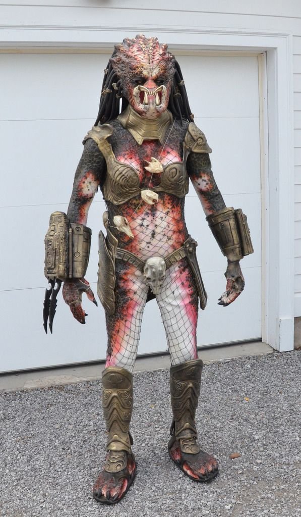
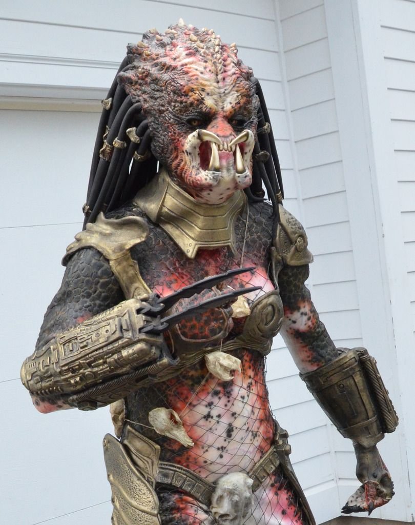
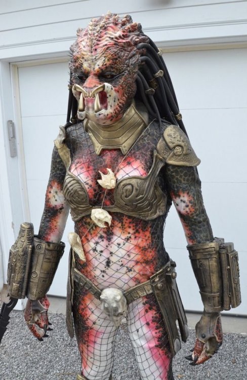
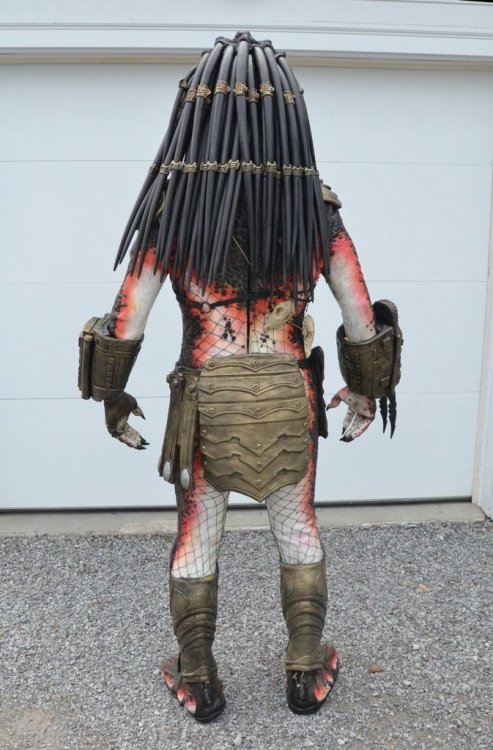
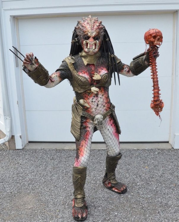
In addition to my Hero Stormtrooper, Sandtrooper, Snowtrooper and Tusken Raider I have a Planet of the Apes Gorilla Solider and now I'm proud to share my Veteran Huntress Predator costume to add to the mix. This was a commission build from a company called Wreav, they are a team of 3 individuals that collaborate to create beautiful costumes. I came up with a concept for how she should be painted and here she is:


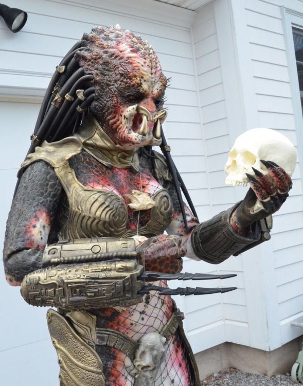 1 point
 -
Thank you@CableGuy and everyone who has helped me accomplish EIB and making my armor look much better. I'm pumped. I have already changed a few things on my helmet and other areas such as my belt that you pointed put. I just need to do a little at a time and maybe become centurion one day. Sent from my SM-N950U using Tapatalk1 point
-
Welcome aboard, Trooper. :-)1 point
-
Hi Corey, and thank you for your EI submission! CRL and EIB Application Requirements: All required submission photos have been posted and I am very pleased to announce your armor displays all the necessary elements to qualify for Expert Infantry. On behalf myself and the entire D.O. staff, congratulations! Other-Armor Fit/Assembly: In this section we review observations made by your fellow troopers and ourselves. Some observations may lead to suggestions to improve the overall look of your armor. Firstly, thank you for swapping out those Hovi-Tips - the new ones look much better! Moving on to the rest of your armour, let's start from the top and work our way down. Overall, your helmet looks really nicely put together. There are some areas which could be improved, which we will run through below. At present, your ears seems to have quite a lot of extra material to them. If you're up for the challenge, you could consider trimming them down to achieve a slightly neater look. Also, your grey tears below the eyes might be a little on the small side. You could consider extending the paint to fill those tears a little more. Reference As below, if you were to consider trimming down the ears a little, you could consider leaning the left ear forward a little to match your right ear. This would help to cover the excess of the face plate that is showing from under the ear. It will also bring the angle of the ear a little closer to some of the screen used examples. Suggested trim lines for the ears. Reference; Suggested trim lines. Reference Round to the front, as it stands your frown paint looks like it could be extended a little on the teeth. There is quite a bit of white on show above and below the grey paint. Whilst this was the case on a few screen used examples, you could consider filling it out a little, like the example below. We would also suggest evening out the vocoder paint by matching the right hand side to the left. NB, as a side note, you might see a slight difference in the tube stripes against the reference photo. This is a very common occurrence when the tube stripe templates are applied to the opposite sides. If you were looking to go all out at some point with your armour, you could consider re-doing them so that the front few stripes lean towards the frown. Moving down to your limbs, you currently have quite large gaps at the elbow. Although it's hard to tell from these pictures, it looks like your biceps and forearms might be a little on the big side, too. For a sleeker look, you could consider trimming down the circumference of the biceps and forearms (leaving about a fingers width around the arms), tapering the forearms towards the wrist, and lowering the biceps closer to the forearms. Reducing the girth of the biceps might also help to bring the shoulder bells closer to your chest armour. Also marked in this picture is the excess material above the ammo packs on the plastic belt. There is currently at least a few millimetres that could be trimmed off. Belt reference; It might also be worth taking another look at your thigh ammo pack. This is currently leaning quite significantly and is possibly mounted too far round to the left side (when viewed from the front. Various screen references show that the third of the five ammo packs is usually mounted a little off centre but to the right of the coverstrip (again, when viewed from the front). Here’s an example of what I mean. This is could be down to the specifics of the armour and the ammo pack, or, it could simply be mounted to far around. We’d be happy to make suggestions if you wanted to provide additional angles of photos after your review. Round the back, it looks like your kidney has slipped down under the butt plate. This has possibly lead to the slight gap between the back plate and the kidney. The butt and kidney should sit nicely against each other rather than overlap. Adjusting your strapping should help to keep the kidney close to the back plate and stop the overlap of the butt. We've also highlighted your rear cover strip on your right thigh. Compared with the left one, it appears to be a little angled rather than straight up and down. Depending on the cut lines underneath, this could be a simple case of removing and reapplying the cover strip. Reference: Thighs This shot also shows the butt plate overlapping the kidney. Adjusting the strapping should remedy this. Reference: butt plate As below, your ab plates and buttons could so with a little TLC. The smaller of the button plates could do with some additional trimming to lose all of the return edge and flashing. As per the reference photo, this should be quite flat with square edges. If you wanted to, you could also consider reducing the size of the painted buttons themselves. A couple things come to mind regarding your TD. As you'll see below, we've highlighted the size of the detail plate on top of the main tube, but also potentially the length of the complete TD. They are usually around 190.5cm in length. It might be just the photo, however, yours looks like it might be a little long or a smaller diameter than the screen used versions. To help with the overall look, you could consider reducing the length of the details plate on top, roughly where the red lines are marked below. On to your blaster, the weathering is a little strong in places. (I know that this is a pre-finished unit so this is no reflection on your build). Areas that might be worth looking at would be to tone down the brass effect on the scope, and also considering repainting the handle - the original handles were made of plastic so would not have the weathering effect that yours currently has. Blaster handle/grip ref: Centurion Suggestions: In this section we prepare you for Centurion. More photos are requested that allow us to make better decisions on possible adjustment etc. If there are any areas of concern they will be discussed here. Because Centurion photos show much more detail than EIB, items pertaining to Centurion might be seen there and not here. We try to point out all we can from what is seen but the final accuracy is the responsibility of the trooper. If you wanted to move up to Centurion, there are a few areas that would need to be addressed, as per the L3 requirements of the CRL. These would include, but are not exclusive to, the below; Looking closer at your belt, the holster attachments are a little on the high side. As per the reference photo, these were traditionally a little lower on the screen used suits. As we touched on before in a previous photo, there is quite a bit of excess material above and below the the ammo boxes on the plastic belt. Also, the corners are a little over cut at this stage. As per the below mark up, you could consider trimming down the excess and adjusting the corners. This would also allow you to get the correct drop box alignment. CRL: The corners of the plastic ammo belt shall be trimmed at a 45 degree angle that that meets the outer edge of the cloth belt. Drop boxes are vertically aligned with the end of the ammo belt with minimal gap between belt and box. Belt and holster references; Holster attachment; Additional areas for L3 include; Side gaps (Ideally there no gap between the abdomen and kidney armor) Side rivets (need to be present and close in appearance to screen used) Han Snap (must be present and correctly positioned) Rubber/flexible hand guards Elastic for shoulder bridges Also, some of the above suggestions, like some of the armour alignment issues, would likely come up again at L3 as Centurion is all about the finer details. Congratulations once more on achieving your EIB. We hope to see you back for L3 in the future.1 point
-
Congratulations on your approval! Glad I could help you along your journey ! Welcome to the white zone !1 point
-
Good luck on the 8th Feb. I’m sure you’ll have a great time, in kit or out. :-) Your blaster’s looking really nice. I also watched that video before painting mine and there are some good ideas in there. Just a couple of small things for your consideration. The t-tracks on the screen used E-11s were plastic, so would not have the metal effect weathering. (Same goes for the grip and the rear half of the Hengstler, neither of which you’ve weathered, by the looks of it). Also, although many hengstler counters had fallen off during filming (as, rumour has it, they were simply hot glued on), some of the E-11 reference material indicates that the hengstler counted would sit a little higher than you have yours. Following the FISD E-11 Blaster reference, the top of the Hengstler counter would line up approximately with the centre line of the scope. As below; Obviously, I’m not saying that you should make these changes, just some details I’ve picked up on over time. :-) Keep up the great work. Dan1 point
-
That is an excellent idea, thank you! I'll do that for sure. Awesome!! That's a relief, haha. Sure! I can take some more off no problem. I'll save that bit for a little later, like re-doing my tube stripes. Once I've got my application for basic acceptance submitted I'll go back over and touch up the paint for L3. :-D Thanks! Don't worry about speed—I just happen to have a lot of time. Enjoy the process! I sure have. :-D Thanks so much!! That means a lot. It has been (and continues to be) so much fun. And thanks for the tips, I will trim some more off the ab return edge—I definitely value comfort. :-) It maaay be a little too late to move my belt higher. We'll see how it looks when it all comes together. If it is an issue, I'll make it happen! Onwards we go! It's been a busy few days. Starting now, I've got a (soft) deadline on my build! For two reasons: Firstly, I'll be moving in about 45 days and would love to have the suit finished before I start boxing up my house. Secondly, I'll have my first opportunity to troop as a TK (if it's ready) on February 8th! The event is with a local costume hobby group I'm with called Heroically Ever After, but they are running a Star Wars segment of the day in partnership with the Southwestern Ontario branch of the Canadian Garrison. Even if the TK isn't ready by then, I'm very much looking forward to meeting the other troopers in my area. Woohoo! Back to the build: With the ammo belt finished, I started working on the drop boxes. I decided to try and make them functional storage compartments for small items like money, ID or keys. I cut out and trimmed the outer and inner boxes, and cut the elastic and velcro strapping I'll use for the assembly: They'll be fastened together at the bottom with nylon, and attach together at the top with velcro. Hopefully this works! If not, they'll still be sufficiently decorative. :-) Tomorrow, the glue will be finished drying and I can attach them to the belt. Next, my acrylic paint arrived in the mail, so I spent a little time with my E-11. Here's how it comes in it's original (gorgeous) state from Brett and Quest Design Canada: Firstly, I stretched and installed a spring I bought off of Amazon. The width was labelled 19mm, which fit into the 20mm back opening of the gun perfectly without any need for adhesion. After that, I glued the back cap on with E6000. Then I got to painting! I followed advice and colour choices from this great youtube video: I also painted the back of these clear cabochons black and glued them into either end of the scope to simulate glass. The smaller one is 10mm and fit perfectly, the larger one is 25mm and had to be sanded down a little. And the result: I am very happy with how it turned out! And finally, I attached my holster to the canvas belt. I used this image as a guide for measurements. Quick note, I found the measurement between drill holes to be approximately 12cm on the AP-supplied holster. I marked, drilled and cauterized the holes. Once again, I fastened male snaps on the inside with split rivets on the outside. Then, I installed female snaps on the holster straps—which, by the way, thanks Mark (AP) for supplying the tan leather straps! From earlier threads, I assumed I was going to have to track some down myself. A pleasant surprise that they were already this colour. :-) And that's where we are for now! Next I'll be installing the tab and slot system on the abs, and then I think all that's left are the thighs and shins (and painting some rivets white). We're getting there!1 point
-
Would a diagonal placement work? Or what about hiding it in that gap between scope, counter and receiver tube?1 point
-
Nice work so far, Tuomas, and fantastic job on the ab/kidney rivet placement! If I could add to the suggestions that have been made, I would recommend doing a little trimming on the tops of your biceps, including increasing the size of the "scoop". This will make them MUCH more comfortable, as well as prevent them from cutting into you and still be screen accurate. Keep up the great work! Reference image1 point
-
My weekend is now complete!1 point
-
Wow, that red led on the front looks cool. I have to do this someday with my blaster. Truly awesome work. Great you are paving th way for others on the wiring and power.1 point
-
Holy mother of all blaster racks! Tino, amazing ideas put into practice here. I love the continued theme using the circuit boards. These stands look fantastic, well done! Above and beyond as always!1 point
-
Incredible progress, Brendan! Just a few minor items that may help.. I realize that you have already set the snaps to hold the belt in place, and that the requirements are met for L3 at this point but hopefully the top of the belt will cover a little more of the ab button plate. Again, not a deal breaker by any means, but just my OCD nature, lol. You may want to think about shaving down the return edge at the top of your ab plate just a bit. It doesn't appear to make your chest plate bulge out, but may cut into you and get a bit uncomfortable while trooping, especially once you get strapped in and your belt is tightened. One of the issues we see a lot is misalignment of the posterior/kidney connection, but you pretty much nailed it. Well done! Gotta say that this is one of the best build threads I have seen in quite a while, sir. Keep up the great work!1 point
-
Thanks for the kind words, Joseph. Hm, not that easy as all these weapons have absolutely different dimensions. First thing in my mind is a wall mounted type of rack, where you can hang your blasters vertically. But then, it would need some sort of lock or barrier to prevent dropping them. Give me some time to think about it. If I come around with a useful idea, I will send you a PM.1 point
-
Impressive...most Impressive1 point
-
Update #08 - Equipping the cabinet Since the installation of the blaster rack inside that steel cabinet, I thought about ways to fill it with Star Wars stuff. The LEGO collection was too big and looked wrong there, but the good thing on this cabinet is the flexibilty. Number and position of shelves can be changed at any time to meet future requirements. During the last years I came across different blaster stands here on FISD with individual styles and always wanted to build some myself. Apart from this, that would be something much more suitable for this cabinet. I thought about two blaster stands with a design based on the existing gun rack. So here is what I did.1 point
-
You're making awesome progress, much better than my slow progression. Love the detail your putting into your posts.1 point
-
The cod should be as high as possible, basicly untill it can’t go any higher1 point
-
Some great info and images in this thread https://www.whitearmor.net/forum/topic/41271-rogue-one-e-11-blaster-reference/1 point
-
I would repaint the black chin.1 point
-
Here is the D-ring again. First coat of paint applied. I may leave it at this, for a weathered look.1 point
-
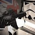
Scope electronics Today’s update is all about the scope electronics. After receiving the BlastFX kit I had to rethink my strategy, because the miniscope no longer comes with a separate PCB. That means not 2 wires with battery supply voltage, but 4 wires going straight to the display. Fortunately, 2 of those carry a 3.3V supply voltage and Paul confirmed that I could draw the additional 20mA required by my red LED from this supply. Since this voltage is regulated I decided to go with the classical series resistor approach to limit the current through the LED: 20190119_144453 The 5mm LED housing fits nicely into the front of the scope: 20190119_153917 Almost ready: 20190119_195036 Here’s a video of the result: M38 scope with miniscope + LED Cheers!1 point
-
I would kill to see your workshop Glen.... with so many builds under your belt, you must have every tool known to mankind, (and I'm envious as hell, lol)!1 point
-
Worked on the thighs this this week. After trying the right thigh on it was clear that I would need a larger thigh than normal. After looking up some forum posts on adding shims to the thigh I decided to build the front of the thigh as usual and keep any modifications to the rear butt connection. The bottom end of the thigh by the knee was fine, it was the upper part that requires additional space. I started by removing the entire return edge at the top of both inner and outer thigh pieces. I marked the crease on the inner part of the armor and then scored it with an Exacto blade. I was then able to snap the return edge off easily. At this point the only sanding I did was to remove some sharp areas where I had cut to avoid snags on my under suit while sizing. Even with the return edge removed I saw that I still needed several inches more. As mentioned I decided to build the front of the thighs as normal to preserve accuracy at least in the front. So I went ahead and trimmed the front butt connection to 10 mm on each side to maintain the 20 mm ridge under the cover strip. Even though this caused the thigh to be smaller when I needed larger I was more concerned with accuracy in the front and comfortable with making modifications to the rear of the thigh. I measured the front butt of both inner and outer thigh and marked it. Then I clamped a cover strip along my measure marks and drew a line along it. After marking the line I clamped a metal ruler along the line and scored & snapped using an Exacto blade. My next order of business is to work on shims for the rear butt connections. At first measure it looks like I'll need to fill about a 1 3/4 " gap at the top of the rear thigh narrowing down to about 1/2" near the knee. I'll take several more measurements when I get an extra pair of hands to help out. Any advise on adding these shims to the rear thigh would be greatly appreciated. Did anybody else have similar issues?1 point
-
[email protected] <[email protected]>; https://dpecp.disney.com/ http://disneypermissions.force.com/WelcomeIntakePage1 point
-
Try this one: https://www.thewaltdisneycompany.com/ and go to the “About” page. You may find what you are looking for there.1 point
-
Really like your hengstler counter so far; the open slits below the sockets and the mesh resolution works well. You are quite the creative genius; as you trial by error, you are already getting to a good place, nice work! Sent from my SM-G390W using Tapatalk1 point
-
Good morning everyone. Just wanted your thoughts to see if this would pass at the EIB/Centurion Levels. I am not the best at painting. I wanted to run it by my fellow troopers. Sent from my iPhone using Tapatalk1 point
-
3D print are in progress. They have been printed, and today I started prepping them. I ran into a few problems, as I'm new to 3D printing, but got it solved. I had the three tubes on the Hengstler in the print, but they got damaged when I tried to drill them out. So now they're brass tubing instead. Perhaps a little too large. The M38's body will be covered with a cast texture, therefore I'm not putting too much work into cleaning it up. And I'm getting more and more surplus, as the project evolves. Now the DD M38 and Hegstler I bought are just extra bits. Either for a later more static build. Or will be sold.1 point
-
Nope, following the curve is the best way to do it - if it looks wierd laying on the table you know you´ve done it right1 point
-
Keep it up! You'll appreciate later that you curved the plastic ammo belt when attaching it. I didn't do that the first time I built my belt and there was stress on the plastic reinforcement inside the canvas belt and quite a bit on the rivets when I snapped it to the ab. It's a small detail but it will help with the longevity of the connections. Regarding the garter belt, I think it's just fine where you have it, you want to be as comfortable as you can be. And when you're fully kitted up it won't be very visible as the ammo belt almost completely covers it up. Most of the general public won't even notice it. When it comes time I'd also recommend running the garter straps along the sides of your legs instead of the front, this allows for more flexibility and movement. You can see how the belt and straps sit in my setup below:1 point
-
My mark 3.0 central capacitors. Thanks again for the tips Christian. Added some color too before inserting the 0.65mm wire (couldn't get .70mm). Now curing will take place with my capacitor ends at the right color. Resisters also had wire upgrades. Green stuff to fill in the larger hole ahead of time, now wires are snug. Thanks for following my crazy adventure!!! Sent from my SM-G390W using Tapatalk1 point
-
Inside the Beltway It's hard to believe I have only two major tasks to complete to finish my build: the Belt assembly and the Shoulder Bridges. I'm saving the Bridges for last because I want to do a FULL suit-up first, and may possibly want to adjust the shoulders in some manner. That could, in turn, shift things around a bit up there, and I want everything just right and aligned before I glue those things on. With that in mind, it's time for the Belt. The Belt Assembly, unlike other parts of the armor, which are either single pieces or paired pieces that have to be glued together, is a collection of several disparate parts. You have the ABS Belt itself, the canvas Belt (Kittell's), two Drop Boxes (each a pair of parts), straps for the Drop Boxes, and the leather Holster (Darman's). To complete the assembly, you'll also be using glue, rivets, Chicago screws and -- ugh! -- a couple more damn snaps. Because there are so many wholly different components here, I elected to prepare all the parts first before actually beginning assembly. As other AM armor owners know, the maker is very generous in including everything you could possibly need no matter what version of the armor you're building -- you'll find both TK and Sandy shoulder Bridges and Sniper Plates, and Hand Plates from all three movies, for example. To that end, you'll find a lot of extras in the Belt department. The kit includes two full plastic Belts, one with Rivet Cover indents and one without. From recommendations here on the forum, I used the Belt without indents. There are also three different kinds of Rivet Covers included: Some tall ones that nestle into those indents on the other belt, plus some not-quite-as-tall ones that also go into the indents, plus some basically flat ones. Again, recommendations here say to go with the flat ones for ANH Stunt builds. These Rivet Covers come in a strip from which you have to cut out the individual Covers. (This is one of the few components of the AM kit not already cut out and trimmed for you; almost everything else is. I love this AM armor!) Cutting these out is pretty simple. Just mark an approximate 1"x1" square around each dome-like button, score and snap. I cleaned up the edges with a little sanding to smooth the scored edge and remove sharp edges, then set the Covers aside to prep the Drop Boxes. In test fitting these parts I found that the inner box was slightly too large to fit the outer box, at least to my satisfaction. I could tell that although they'd fit I'd really have to jam them in there, and I was afraid of splitting something by forcing them together. So, I sanded down the edges of the inner boxes. This was just sand, test-fit, sand some more, test-fit, sand, etc. until I had a smooth fit that was snug but didn't excessively bind. Satisfied with the fit, I beveled the outside edges of the inner boxes a bit. The bottoms of the outer boxes aren't perfectly square due to the forming process, and I wanted a flush fit. The prep for the Drop Boxes finished, I set them aside and proceeded to the ABS main Belt. As I noted, the AM kit comes very nicely trimmed with 99% of the work done for you, but you still need to fine-tune some parts. The AM Belt out-of-the box had long edges of about 7 or 8mm, while the recommended edge for the Belt is 3mm-5mm for accuracy. To hit that mark I'd only have to remove a little, but such a small area to cut meant I couldn't easily clamp a straightedge to it for scoring and snapping. Instead, I marked my cut line on each edge of the Belt, clamped it to my workbench and then used that little hand plane you saw way earlier in the build to simply shave off the excess plastic. Each pass removed a bit less than half a mm, so it only took a few passes to bring it down to size. When recommendations give a range I like to split the difference, so with 3mm-5mm as my guide I shaved the edges down to 4mm each. Once sized, I left the Belt clamped in place and cleaned up the edge to smooth and slightly bevel the edges. As I've recommended several times during the build, any time you want to sand a straight edge and keep it level, always use a sanding block. Next, I trimmed the overall Belt length so each end was, per the Billhag diagrams, about 1-1/2" from the last raised rectangular box on the belt. Now to cut the 45-degree corner notches on each end. There are a few different recommendations for the size of these notches -- confusingly, there are two Billhag diagrams on the forum that, although they have identical drawings of the Belt ends, have different measurements. However, the CRLs state for L3 that... "The corners of the plastic ammo belt shall be trimmed to a 45 degree angle that that [sic] meets the outer edge of the cloth belt." And, yes, that double that-that really tweaks the editor in me. (As an aside, the CRLs are chock full of misspellings and grammatical errors. I've hesitated to mention these because nobody likes a grammar Nazi, plus I'm not an approved member yet and never felt it was my place to say anything. But, now that I'm almost there would TPTB here at the forum like a professional editor to look over and flag all of these? I'd be more than happy to do this.) Anyway, while these notched corners aren't an issue for Basic, I'm shooting for higher levels from the beginning so the CRLs simplify things, especially since no two kits are the same. Or fabric belts from other makers, for that matter. So, like me, if you're going for EI or Centurion, use your belt to determine the size of the notches. First, going forward you're going to need to know where the top center of the canvas belt is located. If your canvas belt is fully flexible, simply fold it in half and mark. Can't do that with the Kittell belt; there's an inner plastic strengthening strip that might snap if you do. If you have the Kittell or other such belt, measure and mark the center instead. (While you're centering things, mark the top center of the plastic Belt, too.) Now, put the plastic Belt on top of the canvas one and mark where the canvas edges meet the ends of the plastic Belt. That is the inside corner of your notch, and it determines the overall size of the notch. Measure this mark and transfer it to the outer edges of the Belt, and pencil a line between the two marks. Bingo, 45-degree angles made automatically. Now just score and snap off these corners and you're good to go. OK, now one more measurement -- see how much the plastic Belt overhangs the canvas one. For me, the overhang was not quite 1/2"; depending on the makers of your armor and canvas belt, this will vary. You'll need this measurement in a moment. Put the plastic Belt aside for now. Mark the vertical center of the Ab armor below the large center button panel. (I'll explain that horizontal line in a moment.) I found it easier to work from the top of the Ab because it kept all my rights and lefts straight -- I recommend you do the same. Plus, it keeps the cod from poking you in the belly. I hate that. Anyway, that's why the photo appears upside down. While you're marking the Ab, mark the locations of the two snaps for the canvas belt. You've probably seen the Billhag diagram for this, but if not here it is. This worked well, but the one side seems off. The 28mm offset on the left of the image (which is the right side of the Ab) worked perfectly to place a snap right under the last raised box on my plastic Belt, but the 59mm offset on the right side of the photo didn't. It put the snap way off to the side where it would have conflicted with a rivet placement later. Instead, I found that 28mm worked perfectly on both sides for my belt. If you also have AM armor you're golden; if not, YMMV. The 15mm vertical offset from the cod ridge worked perfectly on both sides for me to place the snap at the upper part of the canvas belt. Next, I installed male snaps at those two locations on the Ab. You've seen this enough, so I didn't bother with a photo. Now lay the canvas belt over the Ab, aligning the center mark on the canvas with the one on the Ab. The height of the belt isn't critical for Basic, but it is for L3 so let's refer to the CRLs again. "The top of the ammo belt should sit at or just below the bottom of the central and vertical abdomen button panels." Offset the top of the canvas belt below the center button panel by the amount of the overhang you measured for the plastic belt, and pencil a line at this level. (That's the horizontal line in the earlier photo.) OK, this is where your canvas belt is going to rest; the overhang will bring the top of the plastic belt up to the correct spot under the center button panel. Hold the canvas belt firmly at the center to keep it from moving (some masking tape will help), adjust the canvas so it's perfectly level across the front of the Ab, and press sharply on the canvas atop one of the snaps; doesn't matter which one. If you pressed firmly enough, you put a slight impression of the snap on the underside of the canvas -- that's your snap location. Didn't work? Rub pencil on the top of the snap and try again; pressing should leave a pencil ring at the point of contact. Remove the belt and install a male snap there. Adding the second snap is easy, and having installed the first one helps you pull the belt tight. Snap the canvas belt on one side, level it up with your horizontal mark in the center, level the opposite end and pull the canvas nice and taut. Repeat the process of pressing on the canvas to mark the underside of the canvas on that opposite end, and add that male snap. That, hopefully, is the last snap I'll ever do. I've decided I hate doing snaps. You can quote me. Next, I marked and drilled the plastic Belt for the rivet locations. The AM armor comes will little dimples for the drilling spots, but there's a Billhag diagram for that, too. Line up the center marks of your canvas and plastic belts, and center the plastic Belt vertically over the canvas one and mark the rivet hole locations onto the canvas. Punch or burn holes on your marks, and then rivet the plastic and canvas belts together. If you prefer, you can use Chicago screws instead of rivets to secure the plastic Belt. All right, let's snap everything up to the Ab and see how it looks. Yeah. Yeah, that's it. The last step to finish up the Belt itself is to add the rivet covers. Note the pencil marks to help for centering and placement. For this I used a small amount of E6000, just enough at key spots around the corners to hold these securely and not so much that I'd have a hard time taking them off later for repairs if needed. You like my little setting jig? This is just a narrow piece of wood scrap with tape wrapped sticky-side-out over one end. Stick it to the outside of the rivet cover, and use it as a hold when adding glue to the underside, and then stick it in place. No muss, no fuss, and no E6000 on your fingers from gluing such a small part. With the main Belt done, let's move on to the Holster by marking the rivet locations. Yepper, there's a Billhag diagram for this, too. I marked and punched/melted/burned the holes in the canvas, then slipped the Holster straps underneath and marked it through the holes. The tape, by the way, is just there to keep from marking up the white canvas; I marked the locations on the tape instead. Punch the holes in the Holster straps on your marks, and then mount the Holster by your preferred means. I used easy-to-remove Chicago screws for ease of taking off the Holster. On to the Drop Boxes. These things are light as a feather, and to give them a bit of weight to help them hang straight and not go flapping in the breeze, I cut a couple thin blocks of plywood scrap to fit inside each. A bit of E6000 on the back of the blocks secures them nicely inside the inner boxes. And, yes, you're probably wondering how I'm going to rivet the straps on with wood blocks glued inside. Easy answer: I'm not. The CRLs don't require it, so I'm skipping that and using E6000. I'm also not making the elastic loops as those also aren't CRL mandates. One of the things I noticed in almost every build as well in the photos of screen-used Belts in the gallery is that the Drop Box elastic loops nearly always interfere with snaps or rivets, requiring that you cut or notch them for clearance. Plus, to keep the boxes in place it's recommended to glue the straps to the back to keep them from moving anyway. I decided just to skip the loops and rivets, and go with shorter straps that are simply glued in place on each end. To start, I undid those aforementioned easy-to-remove Chicago screws and moved the Holster out of the way. Then, I cut a length of 1" elastic and doubled it over -- visibly, what you see from the outside will look exactly like the ends of a loop -- and applied a dab of glue on the folded spot to hold it flat on the end. Then I glued the two free ends together and glued those ends, in turn, to the back side of the inner boxes and clamped them up till dry. Followed by aligning the outer box edges to the ends of the plastic Belt and gluing the upper part of the straps to the back of the canvas belt. Couldn't clamp it here but a few magnets held it in place till the E6000 set. And that wraps up the Belt assembly. Let's remount the Holster and see what everything looks like. First, a closeup of the back of the Belt. Now, a tight shot of the front. And finally, let's throw the completed Belt Assembly on the floor and take a look. That's it for the Belt Assembly, and that means there's just one thing to do and this build is complete. Next time, it's the Shoulder Bridges, and then on to submission photos. I can't believe I just said that. Did I just say that?1 point
-
Man oh man - BlastFX v.2 with LED strip is gorgeous!! A heads up - not sure if you have your rear site installed already but a gap needs to be in place between it and the end cap so that when the end cap is engaged, there's that approx. 2mm room for the cap to be pushes and turned. Thought I'd mention [emoji28] Have fun!! Exciting build times ahead!! Sent from my SM-G390W using Tapatalk1 point
-
I recently received my AM 2.0 ANH Stunt BBB, this build thread is going to help me a lot. I am definitely going to be referencing this during my build!1 point
-
This will be a great asset for when I get my BBB, thanks for sharing your journey!!1 point
-
Submission pics and approved! TK 926791 point
-
Here is some of the build photos... Getting ready for the head. Getting ready requires help, I need 2 people to dress me. I'm also 6'9" with the head on, I'm normally 6'2". First test fitting of the latex body suit. Painting begins... I have a very wide upper back and shoulders and the body suit had to be modified and expanded to fit. In all her glory...1 point
-
lol! not at all, i am building on a tight budget, gotta cut expenses wherever i can since i got laid from my job of 4 years, i got loads of free time, gotta stay productive;) basically im gonna build everything i can from scratch1 point