Leaderboard


Popular Content
Showing content with the highest reputation on 05/25/2020 in all areas
-
After deciding the faceplate positioning and getting magnets in place in the traps and just under the rivet locations, I was ready to drill the holes for the rivets. Here’s where the ear caps come back into play & time to decide their positioning a bit as well. In order to determine the position of the lower rivets, I needed to know where the bottom of each ear cap would fall. I decided that the holes in the caps here were safe to drill out since those definitely won’t change. I was also aiming to line up these holes with the holes I had already drilled in the cap. Marking the holes with pencil. These were already marked when received, but I remarked the positioning. These are aligned with the divots in the cast with slight deviation to get the upper hole on the left cap just a little closer to center and a little closer to the ear bump. I didn’t think it would have been reasonable to deviate from that positioning too much since doing so would leave a visible divot out of place. The screw heads get countersunk and painted white, so they kinda fade into the background... As a side note here, I looked around a bit at screw positioning and it seems to vary a lot from being roughly straight up and down kind of in a perpendicular line to the ear bump, as it looks for the right ear cap here, and the screws being at more of an angle to line up with the trap line, as it appears to be for the left ear cap... so screw positioning seems to be up to you for the most part: Drilled out, Swapped sides just to confuse you! And a close up on that left ear cap. These will be countersunk before being finalized, so the curve of the divot will kind of slope into that: Ear Screws – Correct drill size 3.5mm or 9/64” (maybe? - I started with 1/8” but they’re quite tight. I may drill these up a size): Putting a screw in place, it is indeed a tight fit. At this size, it does best to screw this in with a driver (non-powered), as opposed to by thumb and forefinger. This leaves thread marks in the hole. So using the holes drilled in the caps and trying to line up to the holes that I drilled in the caps, here’s where those hole alignments may lead you astray again... Wrong: Right side. As an example of poor placement. This is WRONG, lol. Tilted forward. No-no-no-no-no-no... Wrong: Here’s another angle that is also wrong, though it doesn’t look as bad. The positioning is too straight up and down. This is actually where the holes line up on this side. You can see the top hole lining up in the picture, but the due to the angle of the camera, you can’t see it, but it is lined up under there: Optimal: A lot of the times I see the tilt of the ear caps being referred to as being in a line with the end of the trap. What I found to help me out was looking at the original helmets and seeing that the ear bumps are not parallel with the brow trim. The ear bumps are tilted forward, down in the front slightly. This is the optimal alignment. For this picture and the general alignment of the cap, I lined it up with the lower hole. The upper hole no longer aligns with the divots in the cap underneath, so a new hole will be drilled through when it comes time. Over here on the left side, it’s a different story. Here the holes are lined up and the angle of the ear bump already looks good. With the ear caps held in position, I marked the bottom of the helmet roughly in the middle of the space where the ear caps end at the bottom. The faceplate was locked in position with the magnets on, so no issues with positional changing when handling the helmet to drill the holes. Rivets – Correct drill size = 4mm or 5/32” (Maybe? I ended up drilling these at 9/64". This ended up being a good size for the screws, but attempting to push a rivet through yielded no luck - some could, some couldn't. Probably too tight.) I started with the left side since this side fits more easily together. Marking my spots. Doesn’t matter really where these go since they will be covered by the caps. Left side - On this side, I actually drilled the lower hole first since its position was restricted somewhat by the available space to drill into on the cap. This hole got pushed to the back side from the midpoint of the ear cap bottom. Gripped the tubes together for an easy fit while drilling: Note: All magnets were left in place until all holes were drilled and with screws in. And the grip to drill the upper hole, grabbing through the eye hole to pinch both the cap and the faceplate together. If you have any hesitation in your drilling, you still have time in between the drill going through the cap before it goes through to the faceplate. I drilled it straight through both layers. Right side: Marked and gripped through the eye: For the lower hole, screws have been placed in all holes, gripping the tubes together at the peak of their arcs gives a good fit. The pencil mark isn’t visible, but the hole ended up getting nestled right into the little scoop in the plastic there. After getting all the holes drilled and temp screws tightened in place it was time to check out the ear cap placement and check for areas that needed additional trimming. Left side still looking good, but there is some of the cap visible on the faceplate side. Getting the ear in position, marked the cap with pencil along the curvature. These ear caps are going to get trimmed a little tighter as well, so these lines will need to be cut in further than the pencil line. Right side – lots to trim off over here: Look Ma! No more magnets!4 points
-
The upgrade is complete! A few issues needed overcoming, annoyingly I suspect these could have been avoided if I had done an extruder calibration before I printed the upgrade parts. I was only printing 94% of the material I was asking for so everything is a shade small, meaning holes are a tad loose. Managed to work round them all and it's working so I'll leave alone for now but I'll need to reprint a fair amount of parts and rebuild at some point. The part fan is getting a bit loud which may force my hand at some point, so I'll start getting some of the parts I need in stock as time allows. Loving the new quiet cooling fan as well as the flex bed and filament sensor. Really should have done this when it first came out. Also swapped to the 0.6mm nozzle which should speed stuff up a reasonable amount, First on the print bed was a size test for the helmet. Basically take a slice of the helmet around the eyes and print it and see if it will fit or not. Printing on 0.35mm layers, fast with 5% infill to really smash them out. Don't need to be pretty just exist so I can try them on.3 points
-
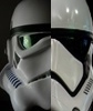
Wow, looking great that helmet. Mine is an Anovos Helmet too and if I can make the same improvement suggestions I received here , for basic level , the crl states: Frown is painted gray and does not leave the teeth area. This is a esay fix, adding a little gray to the edges and you can use some toothpick and mineral spirit (non acetone) to remove some paint. For higher levels, (we hope you may want to go further and have the best look to your armor), I would suggest according to the crl: Correct 'Hovi mic' aerator tips are present. Screens used shall be of a wide type mesh, with the rim of the mic and the inside white or painted white. Changing the hovi mic mesh is easy, I have done several. look at the following photos and you can try or leave it for a future time. Cheers.3 points
-
Haven’t got as much done this month as I was hoping. Health has limited me to 3-4 hours per week, but it’s better than nothing! Got the thighs and shins in progress, and I’m measuring them up to final trim and assemble using the dimensions from the RS suit as a starting point. How does this look size wise? Note: shins will be a little low due to lack of boots. I think the thighs are maybe a tiny bit too large at the top, and I definitely need to cut out the backs a little. Shins might be a tiny bit too large, but it’s hard to tell with the overlap since I haven’t trimmed the back at all yet. Also, as you might have noticed, got the belt nearly done with help from my wife. Just needs a dab of glue to keep the drop box straps in place: And, puppy (helmet is my wife’s btw)2 points
-
Hey Ryan, it’s pretty normal for the hand to be snug going through the wrist opening. The elbows are a bit weird and can be adjusted with a hot water bath. Don’t get hung up on the 15mm. Make the arms fit. Just keep all of your arm cover strips the same size – so that the biceps and the forearms have the same size cover strips. Another trick is to have slightly larger cover strips on the front, let’s say 17 mm, and then larger cover strips on the back like 19 mm or something. so yeah, I would trim to the 10 mm per side and see how it feels from there. Be sure to wear something underneath about the same size as your under suit. good luck.2 points
-
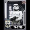
COSTUME INFORMATION Armour, Helmet and Neck Seal: Anovos TFA Gaskets: Imperial Gaskets (rubber) Belt: Belts of the First Order Hand plates and Holster: R2Dan Boots and Gloves: Imperial boots Undersuit: Stormtrooperundersuit F11D Blaster: Resin kit (Justinian) Name: Jasper Tan Height: 170cm Weight: 80kg TKID: 7867 Garrison: Singapore Garrison Level 1 approval: https://www.501st.com/members/displaymember.php?userID=13500&costumeID=326 APPLICATION PHOTOS FULL BODY HELMET ARMOUR DETAILS NECK SEAL CHEST, YOKE AND BACK THERMAL DETONATOR SHOULDER AND ELBOW GASKETS SHOULDER BELLS BICEPS FOREARMS GLOVES AND HAND PLATES ABDOMEN COD AND POSTERIOR BELT UNDERSUIT THIGHS KNEE GASKETS KNEE PLATES SHINS ANKLE SPATS BOOTS F11D HEAVY RIFLE ACTION SHOTS For the DO's kind considerations, and do feel free to ask me if you need any clarifications, thank you!1 point
-
For covering the screws, i would recommend to trim them first, you can use a square of foam, glue it with superglue or zap a gap. Place a piece of Velcro to attach the lenses. This is a practical solution. another practical solution for padding and easy to clean after trooping.1 point
-
RS armor will be more accurate1 point
-
Fortunately you have a lot of options given your height. ATA, AP, etc. you can check with each to find out time (wait list) and cost. EDIT: it also depends on where you are located, e.g. US vs. UK/EU and shipping/duties.1 point
-
Hi and welcome to FISD. If it were me I would get the armor from RS (they have a nice sale going on right now) and the helmet from AP - good luck1 point
-
This is my Helmet, as you can see the vocoder has been improved too by removing the paint in excess . Cheers1 point
-
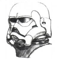
Hi Caleb, looking good. from my view, I think you can rotate the left ear a bit to align the top screw with the trap (green point) , as in the reference you posted. hope this scheme is clear, i'm not good drawing . cheers1 point
-
Sure you can, just some painting like Joseph mentioned and you’re set1 point
-
And the second thing that was stopping me: I wasn’t sure what size to drill the holes at. This is the easier one: I have seen 3mm & 4mm and for whatever reason, the less popular “standard” measurements seemed to elude me. Not wanting to rely directly on sizes that were stated without knowing what hardware was being used, eventually I smartened up and researched what drill bits to use based on the hardware you’re drilling for, and for just about everything but wood, you drill it to size. What I don’t yet know, I am more than willing to learn and fold into my repertoire. I am sorely tempted to go buy some calipers so I can have a more exact way of measuring things, but until then, I can compare the drills to the hardware by eye and go with that (pictures are your friend when it comes to this. Builder’s note: Do you have poor eyesight? Do you have a camera? You can take a picture of things and then go look at the picture to make judgments when your eyes may deceive you. Pictures allow you to zoom in to a much greater extent than what your eyes are capable as well as sometimes offering visual guides in the frame to help with straight-line features, etc. Big building point here: Don’t be afraid to take pictures - & - Take a lot of pictures. It doesn’t matter if it’s going to be posted or anything, take pictures. You can use pictures to review what you are doing in a more objective sort of manner to make more informed decisions. Feeling iffy about something: take a picture. Wanna know if that one bit lines up with that other bit: take a picture. I think you get the picture ; ) Ok, I’ll stop, lol I did a little mathing and came out with the following conversions: 2mm == 0.08” =~ 0.0781” == 5/64” 2.5mm == 0.10” =~ 0.1094” == 7/64” 3mm == 0.12” =~ 0.1250” == 1/8” 3.5mm == 0.14” =~ 0.1406” == 9/64” 4mm == 0.16” =~ 0.1563” == 5/32” As a side note: You can drill it up by 1/64th” size if you’re not sure, and you should still have a good fit. If you’re really unsure, you can drill test holes in spare pieces to determine the size that works best. I didn’t think about this until after, but it is an option. Hovi-mix Tips – Correct size 3mm or 1/8” (tight fit. For my purposes, tight means you have to rotate it to screw/unscrew the hardware as opposed to it just sliding in without friction - I may have widened these out to 9/64" eventually): Picture comparison: 2.5mm ~ 7/64” - you can easily see the threads on both sides = too small Picture comparison: 3mm ~ 1/8” – Resting the mix tip screw against my drill and holding the drill bit in line. The threads are visible on both sides again here. This is a tight fit for the screws. Holes marked for drilling at existing divot locations - These guys you can do any time. There's only one place for them, so no waffling: Right side hole drilled. Zooming in, you can see a slight crack at the bottom. I may need to do some reinforcing here as the plastic is very thin. And the obligatory “test the fit pic”. I did a number of test fittings like this including putting on the “S” trim and testing fit size comparing the differing faceplate positioning.1 point
-
Wow, what an ultra clean submission. Good luck mate.1 point
-
No expert but I have some thoughts haha The stock strapping is fine to use, especially when you first get the suit and are figuring out how to get it to hang so it's comfortable and looks right. But if you're going to be putting a lot of miles and troops on it, eventually snaps will be a better solution. The main issue with the Anovos stuff is that the Velcro and really the adhesive aren't great. Even replacing the loop side that sticks to the armor with 2" industrial does wonders. For the back of the shins, I just use regular 1" Velcro that I can buy by the foot at my local Ace hardware - you want it to be able to open and close, so industrial is too much. Haven't tried the ultra thin yet, but it might not be enough hold...1 point
-
Thank you looking forward to your progress good to see a lot more R1 tks getting build1 point
-
I got my left forearm rough sanded and taped up as far as the overlap allows without trimming. This would leave about a 20mm ridge once butt joined and my hand just barely fits through. I think it may fit more flush with the butt join and I might be able to squeeze a few more millimeters and maybe get to the 15mm ridge and cover strip. Should I trim to 10mm per side and reassess? It is a little snug at the joint near the elbow but I can probably fix with a hot water bath once it is all trimmed. Ryan1 point
-
Here are the ears attached with my tiny clamps. What do you think? Front and back of each ear need a bit of trimming still, I'm waiting on the helmet to be connected before I trim more.1 point
-
Great !! Post a lot o photos, search the forum and ask questions, we are here to help.1 point
-
Congrats on pulling the trigger on a kit! Good luck on your build.1 point
-
Good luck with your build! Post lots of pictures. Oh, keep in mind that ABS paste does not have much strength - it is mostly a cosmetic fix. You might want to reinforce the crack on the back with a piece of ABS glued to inside of the helmet or even a bit of old t-shirt material and CA glue (lazy man's fiberglass). I guess it depends on the severity of the crack.1 point
-
AWESOME! Congrats for real now!1 point
-
Great progress, Shane! At some point you'll need to tell me what your favorite tracks of the saga are. I'm pretty sure mine are all from the OT, though there were also standouts in Phantom. As for shin velcro, my understanding is that most of the Anovos strapping should be replaced, but I think you'll find @TheRascalKing to be the expert on that front. Maybe he'd even sell you some of that ultra-thin he got, assuming he has excess. I might even be interested myself. A bathtub could work for a heat bath, but you'd lose a lot of volume due to the large surface area of a tub. Perhaps a 5-gallon bucket would work better? Might not be tall enough for the calves, though, depending on how much reforming you need to do.1 point
-
Thanks, The ears do cover the seams, I could trim a little more if I wanted but I figure I can always trim more later. I'll take a picture with the current ear shape/location, that might help. I've tried it on like this, it fits fine as far as I can tell, but I wouldn't know if it didn't. I guess test screws won't hurt anything (that's what she said?) So I'll try that. As long as they aren't blocking the ear holes I guess it wouldn't matter much.1 point
-
Congratulations trooper, well deserved.1 point
-
Nice work and some great images, good luck (not that you should need it )1 point
-
Waiting to see your progress with the armor ...Good luck1 point
-
Looking forward to seeing the progress, good luck1 point
-
Big Brown Box Day for my R1TK from 850 Armorworks is today! Woohoo!
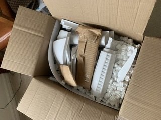 1 point
 -
The slightly difficult thing about this blaster is that the trigger is brass. This really complicates things with painting because it's difficult to paint the trigger brass once the blaster has been assembled. Here's the trigger. It has an opening in the front to mount a spring for the working trigger. It's probably easiest to paint the trigger before assembling the frame. And if I'm going to paint the trigger brass now, I might as well do the few other pieces that are brass as well. I started off by spraying a primer onto the parts. I also test fitted the trigger spring and once I attached it, I couldn't get it off anymore. :-) So I might as well just cover it with some masking tape and move on. I'm partial to Tamiya lacquer paints because they apply thinly, don't obscure detail and dry quickly. Although they are a little expensive. For these parts I used Tamiya Surface Primer and once dry, followed up with a Tamiya Gloss Black. The parts that are brass are the trigger, cleaning rod, cleaning rod holder, safety switch and this little block on the ejector port. Actually, the little block on the ejector port flip-flops between silver and brass on the show. The safety switch changes orientation too, but at least stays the same color. :-) The other paint I'm partial to is the Alcad line of metallic paints. Their chrome is amazing but like most of their paints, needs to be applied with an air brush. For the brass color I used Alclad Pale Gold. I think they used to have an Antique Brass paint but I haven't been able to find it anywhere locally or online so I'm thinking it might be discontinued. Anyway, the pale gold looks good and again these lacquer paints dry almost instantly. Much of the trigger will be hidden inside the frame. One thing I started doing with smaller parts was to place a "ring" of masking tape around my finger, sticky side out. Then I can attach small parts to my finger for painting and slide the tape off and stick it to a table to dry. And here are the parts. I think I'll still apply a clear coat to these once they are completely dry. And yes, the cleaning rod looks bent. It's pretty flexible but once attached to the blaster it will be held straight. Mark1 point
-
Looking good! Thanks for the great pics of your strapping!! So many people go from pieces to finished and don't show how they put it together. I'll be referencing your build when I'm figuring out my straps!1 point
-
I have just posted similar on the 501st, if we need a better more specific rule.in the charter then we need to.propose one. A much more pro-active way forward. Sent from my SM-N960F using Tapatalk1 point
-
Please don't buy into the "I got the moulds in a trade" bullshucks. Someone has tried to disguise where they come from when they were created. Someone has form for doing this time and time again and someone has been very quiet on this subject.1 point
-
Back plate is coming along nicely. There is 1 issue I need to fix however. As I scaled in only 2 planes, the O in OII is oval. I have a plan to fix this but I'll come to that another time. Also one thing I would do differently next time. As it is I cut things neatly into a grid essentially: Next time I will cut more like "a brick wall". Not only should this make things stronger as there are less long straight cracks, it will also make lining stuff up easier as you can use the overlap part as a reference. I would still use fibreglass to reinforce things but it wouldn't need to work as hard. Also one back part (top row above) had some big over hangs using a lot of support, almost as much as the part. So I have split one into 2 to allow me to re position it reducing the support need but adding 1 more seam to glue and weld.1 point
-
Well, he was accused of recasting his ANH face plate and data surfaced for that years ago, yet it fell on deaf years. Even for the armor (most recasters cast from the inside of a suit which is why they tend to be smaller than the original. The working theory based on evidence people saw was that he recast from the outside a TE suit and then did an awful lot of work to make it more accurate). Thank you Mark for posting up such conclusive evidence. I am sure the decision to do so must have not been an easy one, and it took time and care to ensure that your claims were accurate and detailed to the point that it is obvious to anyone what happened.1 point
-
Hi Nada, What I did to avoid the sniper Knee to turn is to place a piece of velcro in the front part of the Boot and the Shin and No more problem. Hope this can help. Cheers.1 point
-
FOTK? I think I have read it being done but it is likely not very easy. I took my ANH apart.1 point
-
Hey Nadas looking good brother. Regarding the Ab/Kidney side gap, according to the CRL there is no measurement requirement at basic however, please check with your garrison's GML as to what they require. The following is all that is required for basic Ab to Kidney. That said L2 and L3 will have tighter requirements. Abdomen Armor The abdomen armor has a button area that matches the color pattern shown (3 blue + 6 gray); buttons are approximately 7/16" (11mm) in diameter. Besides filling in the thigh gaps front (as suggested by Aizenoso) do the same for the rear or trim for mobility. I also suggest you remove any return edge that may help the armor sections sit closer to your body.1 point