Leaderboard


Popular Content
Showing content with the highest reputation on 02/20/2018 in Posts
-
Well, EIB application posted! Anyway, I want to thank everyone for their input - either directly or just by posting their own builds. I can't begin to list all the people that helped but I will mention Sean, Dan, Q, Brad, and especially Daniel. Thanks guys! You provided sound advice and/or talked me off my OCD ledge. I also have to thank Tony (ukswrath) for his awesome build threads - this was the foundation for most of what I did. And thank you Mark at AP for this great kit. This is an amazing community - I'm proud to be part of it! TK-34575 Up next... TD. Gonna get dirty.4 points
-
Quick update. New scope rail arrived from Tino, scope finished with screws added to the front and Counter numbers added. I think I’m finally almost ready to start chucking it all together [emoji23] Sent from my iPhone using Tapatalk2 points
-
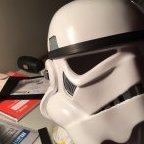
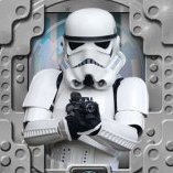
Hi folks! So I've had several questions regarding how I did my helmet lenses and so I thought I'd put a little guide up for anyone that may be interested in the process I used for their own builds. I think it came out rather slick with a neat end look while being solid and easily replaceable. Here is a shot of what this technique looks like when completed from the inside: Materials: Sugru moldable rubber Shade 3 flexible welding visor - https://www.amazon.com/gp/product/B00209I0UG M3x20mm screws and acorn nuts Index cards Pencil Xacto knife Micro ruler Scissors 220 grit sandpaper Drill Dremel and/or belt sander Vise Thin black heat shrink tubing Step 1: Create eye socket templates I don't have a picture of this first step but you see me using mine in later steps. So all you do here is take an index card, ho ld it flush over the eye opening inside the helmet then with a pencil trace the opening from the outside. Make sure it is centered on the index card because you are now going to extend it for overlap margin. With the socket outline traced on the card, using a ruler measure half an inch out from the outline and place a mark, do this many times tracing around the outline so you're basically making the original socket outline half an inch larger on all sides. Then simply draw a new line around this outer outline and cut the template out with a scissor. Make sure you label what eye socket each label pertains to, and store these for future needs even after this project is done in case you want to cut new replacement lenses, switch out colors, etc. Step 2: Shape a rubber mounting surface In this next step you are creating a rubber mounting surface that the lenses will bolt onto and create a flush connection to the eye sockets. Take your Sugru (I used like 5-6 packets per socket) and create a nice think outline around the whole inside of the socket. You'll want to ensure that the rubber around the socket's plastic mold is slightly taller so when you rest a lens onto it is sitting flush on the rubber bed. You have a lot of time to work with the rubber before it starts to set so take your time and get the outline right. Important last step here, after you're happy with the rubber mount take an index card (or two to make it thicker), lay it against the rubber outline and press down lightly to ensure that you have an even surface all around to avoid having an uneven mounting surface outline. Step 3: Cut your mounting bolts I used five bolts per lens, you may want less or more but found that to be a happy place for getting the connection tight. Ok so here you are going to take your M3x20mm (you don't need to use this specific bolt size, can be M4, M2, whatever, just something you're happy with size wise) and cut them so you have a set that will have even height protruding upwards from where you will be mounting them. The gist is you will be adding these bolts to the rubber mold you created in step 2 with more rubber, but first you need to look at where each bolt is going to rest and measure how far over the rubber they are sitting uncut. Since the topography of the helmet here varies, some bolts will be extending quite far, others not so much, and you want an even extension from all bolts. I wanted about 8mm of extension to bolt into so I held a screw in the place it will be mounted, measured how far above the rubber it sticks out to calculate how much I needed to cut (so if it stuck out 13mm I cut 5mm off). Keep track of where these screws are going to be mounted since you measured it for that spot! As I was measuring and cutting, I placed them on my templates at the spot they will be mounted. To cut them down I just put a nut on the screw exposing the amount after the nut equaling how much needed trimmed, then put it on a vise and dremeled that excess off. You may find a cutting solution that works better for you, but I found that easy. Careful handling these little bolts after cutting them, they will be very hot! NOTE: Never cut metal bolts that are already mounted in your helmet, besides making a mess their heat will likely melt the plastic creating a huge problem. Step 4: Mount your bolts Now that you have your rubber mounting surface and your bolts cut for specific locations around the surface, it's time to attach the bolts. Using Sugru again put a nice wad on the bottom of the bolts, then just mold them to the mount at the correct locations where they were measured. Get the attachment between the mount and the bolt nice and tight, use more Sugru liberally and work it in. The one thing to be careful of is to not have any Sugru on the bolt that goes over the height of your mounting rubber from step 2, otherwise the lens will stop bolting in too high and not rest on the flush surface you created. However, being rubber this stuff can very easily be trimmed with a Xacto knife, so you can just snip any excess off to keep your base mount surface flush. After you've finished mounting all your bolts, you may want to double check you didn't get rubber smudges on your helmet and clean it off well, don't worry if you do, it will remove without much effort. Clean your hands thoroughly as well! Now that you have your cool rubber mount with sized bolts, you need to let that rubber set for 24 hours. Step 5: Add mounting points to your templates After you've allowed your rubber to set overnight, you'll be taking your two socket templates and marking where the bolts you mounted relate to it. Simply press the template down onto the bolts to make impressions on the paper where the bolt tips are, then punch through those holes with a pencil. Afterwards, place the paper template into the actual bolts to ensure that all the bolts align right with your template and your template rests nicely into the mounting surface you've created. This is a preview of what your lens will look like when you cut them to the template shape and drill the holes! Step 6: Cut and shape the welding lenses I used a shade 3 welding lens which is flexible and fairly easy to cut, after looking around and trying a few options I found the one linked above in the materials list to be the best for this project. Ok so what you're going to do now is rest your templates onto the lens stock, trace the outline lightly with your Xacto knife (just enough so you can see where you need to cut), then cut out each shape with your scissors. Your cut lens will be a little rough, so curve it more naturally by (carefully) running it down a belt sander or Dremel tool. You just want to make the shape of the lens natural and curve to make the template and avoid any sharp points (your eyes don't like sharp points). After that, take some sandpaper and sand the edges all down nicely so they are nice and smooth. For the last step, place your paper template back onto the cut lens, then with the Xacto knife mark where each hold is going to go. Take your drill and open up each hole, making them plenty big enough for the bolts to go through with some room for flex, but not too large that your acorn nut won't compress down against it. Note that while doing all this, be careful not to scratch the lens surface by a stray cut or tool. Step 7: Mount your lenses Ok almost there! Here you simply need to push the lenses down through the bolts and screw in your acorn nuts to secure the lenses down into place. You may need to bend the lens a bit to get the fit to work, here is where making those holes a little bigger than needed helps. Whatever you do, try to not allow the tops of your bolts to scratch your lens. To hide any excess exposed bolt shaft I cut very small pieces of black heat shrink tube and put them on the bolts then put the acorn nuts back on and screwed down tightly. Conclusion: Ok so this may not be the easiest method of creating and mounting lenses, but the end result is pretty nice (in my opinion), and I like the effect having the acorn bolts gives. You have a well sealed lens over your sockets without any gaps by virtue of the rubber mounting surface and bolts securing them into place. The lenses themselves aren't flimsy and are high quality, plus easily cleaned with mineral spirits if heavily soiled, or just your standard glass wipes. Another plus is you can easily replace them just just unbolting them! I hope this guide helps anyone interested in this type of technique, cheers!1 point
-
Building this armour has been more rewarding than I could have ever imagined. I loved the process and I now love looking into my office and seeing actual stormtrooper armour sitting there. I thank everyone who contributes to this site, without this I would have been lost. In the context of the 501st, I'm sort of in the boonies but I'm going to find any excuse to wear my armour and troop. My son has a show and tell at school next week - guess what he is bringing. Thanks again, FISD!1 point
-
Mandatory Information Name = Jessie H. TK ID = 10272 Legion Profile = https://www.501st.com/members/displaymemberdetails.php?userID=21573 Garrison/Squad = Southern California Garrison, Orange County Squad Forum Name = JHowe102 Armor = Anovos Helmet = Anovos Blaster= Hyperfirm Optional Height = 5ft 8in, or 173cm Weight = 115lbs, or 52kg Boots = Imperial Boots Ammo belt = Anovos Canvas belt = Imperial Issue/Kittle Holster = DarmanProps Hand Plates = latex, justjoseph63 on FISD Electronics = Aker amp, TKTalkie, 5V fan system and hearing assist Neck Seal = Anovos Armor Photos Front Helmet Off Full Body Front Full Body Back Full Right Full Left Right Side Detail Left Side Detail Helmet Detail Photos Front Sides Back Hovi tip detail Lens color (Backlit if necessary) Accessory Photos Holster Attachment Neckseal Blaster left side Blaster right side Thermal Detonator Boots Action Shot Optional Interior Strapping Abdomen Detail Handguard Flex Cod Details I've been a 501st member for almost two years and in that time I've made many friends in the Legion and in the other clubs we work with as well. I enjoy trooping across all Squads and even Garrisons, and the distance doesn’t mean a thing to me. It’s the people we troop with and the people we troop for that makes it all worth it! Every troop is a unique experience every time that I get to share with my fellow Legion. I love the Legion and aim to make the Legion and all of my fellow troopers proud with as much service as I can possibly offer! Thanks for looking!1 point
-
I had the same issue. I just reinforced the area with spare ABS glued to the inside to thicken it up. I went edge to edge on the top and bottom so the area couldn’t flex as easily and crack.1 point
-
Thanks for the frame tips, guys. Sent from my iPad using Tapatalk1 point
-
Thanks for the encouragement guys. I was telling my wife yesterday that this build is like a snowball. It started off slow but once I got rolling, I can't stop it! Getting pieces put together and what not, it is all I think about now. Hoping to be ready to paint by next week.1 point
-
Glad the method worked for you, too! Coming along wonderfully, AJ!1 point
-
Those bad boys aren't coming off, nice work AJ1 point
-
Actually it did smell about as bad as the inside of a Tauntaun, but I was prepared for that and did all that work in the garden Yesterday I spent some time with painting a couple inside parts of the blaster that I screwed up when replacing the resin screws with resin ones, mainly because the cheap no-name brand dremel can sometimes be very unpredictable.. No pictures tho because I think these tiny changes aren't really worth showing. Also I might finish the blaster mod soon as I have already got a decent plan of what I want to do and I really just want to get that out of the way (I really enjoy tasks that I can split into subtasks which are like a small success at least). So let's see how that'll go..1 point
-
Beautiful build! Looking forward to this!1 point
-
So true! I literally wanted to start doing everything.1 point
-
Nice work! The hardest part in all of this is finding where and how to start... and you just did it!1 point
-
haha.. I have irons etc. Even have one of those magnifying solder setups I'll wait for the fans to die first.. hahahah.. I'm brutal like that.. besides.. I will need a set of Fans for my Tie Pilot. We gotta get together some day soon though! You are working all the time!! Laughs oh and ANSWER YOUR FACEBOOK!! LOL1 point
-
And if you get an inline fuse and buy new fans from amazon I'll put a new set together for you. It takes me 10 minutes or so to make the last time I did it. I might take a bit longer because I can't remember how they look but it's like riding a bike as soon as I see yours I'll know. Just need to find my iron. Can't find that bastard anywhere.1 point
-
Really sorry to hear of your experience, Tom. As the others have said, try not to let that sour your Stormtrooper ambitions and excitement. As Chris said, we have an unbelievable selection of armour makers here in the UK and would be happy to help you on your way to a top notch suit, hand-in-hand with some excellent customer service. Best wishes, Dan1 point
-
Thanks man, im going to give it a break for a while, but ill definitely be back to check out the Vetted sites once ive got this mess sorted out.1 point
-
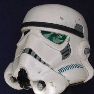
Alright - Good fun news stuff first - Wow.. I had a blast at the strong museum and was even in the papers... I was talking to a funny little Rey as the newspaper took the picture. Laughs.. Anyway, the Museum is an amazingly fun place to hang out for a weekend!! Loads of fun. I hope to visit this year. What else is new with me.. oh.. I'm a Command member for 2018 in the Canadian Garrison. That's exciting. I get to work with some amazing people and we're looking forward to having so much fun this year!!! What do you have on the go Brattie? Well I have completed a Tie Reserve, bridge Crewwoman, and am working on my MSE Droid and Tie Pilot armor as well. FUN FUN FUN!! - Bad / sad news - My TK armor It has taken a beating. I've worn it now for around 400 hours and it shows. I developed 3 cracks in my bucket on the lower opening that you stick your head into. I've put in a preventative drill hole to hopefully prevent the crack from spreading until I can put in some other structuring to support/fill the hole. Unfortunately I don't have ABS Paste and if you are new and building your TK, SAVE THE SCRAPS!!! MAKE ABS PASTE!!! My Fans.. laughs.. When I start them they go.. SSSCCKKKKERRRRRRRRRRRRRRRR then quiet down... Too much rain, water and sweat getting to them. Laughs. They are still working. After a scary moment with a friend in Vader I'm considering putting in a fuse on my fans as I'm running them off a USB Powerbank. His switch melted and his head started to smoke. Was an awesome effect for smoldering vader but the human inside wasn't too pleased. Anyway, he was alright, but it did raise a concern that perhaps we should all be putting in-line fuses into the Fan systems of our helmets. No one deserves a burn or such when doing awesome stuff for charities etc. Straps I have a few straps that are falling apart now too.. my right elastic strap between my forearm and bicep is shot. So all in all I have some repairs ahead of me. Well that's all from me!! You are all now.. Up to date.. Laugh ~Brattie out~
 1 point
 -
Looking sharp Greg, we will be with you as soon as possible.1 point
-
I've had grainy tins before, usually when they are about a million years old. I had to bin my first #14 which I got at a local small hobby shop as it was just no good no matter how much shaking/stirring it got. If all cans are from the same shop try a different one. If they are the new designs maybe add a small stainless steel nut to the tin before shaking to act as an agitator. You can buy specially made balls for this purpose but their mainly aimed at acrylics which can rust some stainless steels.1 point
-
You really have to shake the shit out of the cans to break up the pigments.1 point
-
Great job congratulations!!!! Mark (AP)1 point
-
Looks good! Sent from my iPhone using Tapatalk1 point
-
So true, I see all my mistakes in my TK.1 point
-
Some of us have no choice as we are just too thin, some like pieces to fit snugly but you don't have room to put on any weight I also have padding on the inside of my ab/back, most wouldn't need too. A finger or two of room is fine, especially if you have trimmed to the minimum size cover strips and trim lines.1 point
-
Nice work, get in there and get trimming1 point
-
Done!! I could of course have done more smoothing, and there are some cracks and some blemishes that I didn't fix. But as with my kit, nothing is perfect, just move on before you go nuts! (Yes I am missing a screw under the forward grip, which I fixed right now )1 point
-
Great to have you here, Jenny! As Q (gmrhodes13) mentioned, Imgur is REALLY easy to use. Just click on the center of the photo you want to use and choose the Direct Link option. Easy peasy. Have you checked out Cricket's build thread? https://www.whitearmor.net/forum/topic/41502-crickets-wtf-hero-build-even-more-tk-for-the-vertically-challenged/?tab=comments#comment-556128 Lots of information there for those that need to cut things down a bit, and I'm sure that she would be be willing to answer any questions for you.1 point
-
Hi Bryan, thank you for your patience and EIB application. Lets get stuck in. CRL and EIB Application Requirements: All the required submission photos are present and your armour meets all criteria as set out in the level 2 CRL With that said, congratulations on a beautiful set of armour. Tony and myself would like to both congratulate and welcome you to Expert Infantry Rank. Only 2 very small items that could do with minor correction. The frown is very tidy, but you could paint it closer to the gum line leaving less of the teeth unpainted. Your frown looks more like the Hero style rather than the typical Stunt version. Dressing issue only but a tweak and your TD will be sitting center and perfectly. Centurion Suggestions: Because Centurion photos show much more detail than EIB, items pertaining to Centurion might be seen there and not here. We try to point out all we can from what is seen but the final accuracy is the responsibility of the trooper. This is also where we try and get you in the best possible position for a successful Centurion application and I am glad to say, you are definitely on target. Nothing to add here Congratulations again Brian and we shall see you in Centurion review soon1 point
-
You are on the right track. Asking questions and checking your measurements before making cuts is very smart. Good luck! I will be watching your build.1 point
-
Oh, just noticed you posted this here too, hahah. Anyway, what I wrote in the other thread: Hi Jenny, will follow your thread here as well as on CCG forums! To keep cut lines straight, I used a long metal ruler and clamps! Andy likely shared quite a bit of info with you, but please don't be afraid to post about any questions you might have!1 point
-
Hi Jenny, will follow your thread here as well as on CCG forums! To keep cut lines straight, I used a long metal ruler and clamps! Andy likely shared quite a bit of info with you, but please don't be afraid to post about any questions you might have!1 point
-
Shin Boxes Time to add some shin boxes to the left shin. When I trimmed the boxes they still had flared outcroppings at the base that I wanted to slim down to create a cleaner look. Belt sander to the rescue. Before and After Next step was to create a way to fasten the boxes to the shim. To do this I cut out some ABS strips cut to rest inside the boxes. After some trial and error, I ended up using 8/32 x 1/2" Chicago Screws for box 1 and 8/32 X 1/4" for box 2 (labeled below). Box 1 sat over the interior cover strip and needed an extra bit so the interior screw could reach it. After assuring that they would fit, I drilled 2 holes in each with a 7/32" drill bit, inserted the female ends underneath and glued the apparatus in with E6000 and set aside to dry. Thanks to Ruthar for this method. After that was done, I set out to create a template to mount them. Referencing the CRL, I did my best to estimate where the top clip greeblie would go and then outlined the boxes to match. I then measured the distance of where the companion screw would go and noted the distance on the shin. In the end my template looked as seen below. I marked the boxes accordingly so as to not confuse them. Once I was confident in the hole positions, I drilled into the shin and made the connections. Done for now.1 point
-
I use PLA primarily. I use a Markforged printer at work that uses nylon. PLA does not give off an offensive odor like ABS. PETG is supposed to be a good material for strength. ABS and PETG work best with a heated bed. Matterhackers has some good information on different materials.1 point
-
KB posted on his FB page the other day that he will now be providing a resin TD and 2 piece forearms in his future kits. REMEMBER OUR SACRIFICE future builders!1 point
-
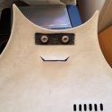
Thermal Detonator Part 1: This was perhaps the trickiest part to assemble. It requires a lot of clamps, magnets and patience. It doesn't help that one part of my TD came to me like this for some reason. This is the bottom half that connects to the 3 ridged rail that hooks on the back. It should not have been cut like this. I didn't realize this until last week when I set out to trim and assemble it even though I received the kit in November. Not willing to wait on a new piece from KB (I didn't even contact him about this) I set out to fix it. To do so, I took a dremel to the rough edges to smooth it out into as best a half moon as I could. I then traced that shape onto some spare ABS sheets provided with the kit. Using some cover strips on the inside, I glued the insert to the original piece. Good as new? With that out of the way, I set out to glue the two halves together. I glued the bottom seam together first. It seemed to fit best with the outward facing half (the part people see) overlapping the inward half. That's the easy part. Next comes the hellish portion. I don't have pictures because I only have two hands. I'll refer you to my inspiration builds linked in the OP for pictures on how they did it. As others can attest, there is a TON of torsional force when you try to fit them together and have the side openings resemble anything close to a circle. Otherwise, at least in my case, they were more oval. So it required me to apply the Weld-On, quickly apply whatever clamps and magnets I could as quickly as possible and then physically hold the pieces together to form the circular openings. I did so by glueing and holding one side until it set well enough (about 10 minutes) then glueing and holding the other. Not cool! I then applied E6000 to the end caps. The left cap sticks out about 1" and the right cap sits flush. The left side turned out better than the right, hence the clamp on the right to make it more circular while the E6000 dries. Results of that still pending.1 point
-
Lots of parts that were half finished or pending are starting to come together. Yoke: I have been putting off the yoke assembly because it just seems a bit daunting. I had to start it at some point so today was as good a day as any. I started by clamping the bridge and the shoulder arches together to see how they fit. It ended up looking something like this. On KB's armor there are some indents in the center of the bridge that lines up with arches. On other armors those indents are cut out and the convex ends on the arches fit into the openings. I thought about cutting the concave indents out on the bridge but realized that the pieces fit fine anyways so I saved myself the effort. That is an option if you so desire however. Observing the fitment check was good because it showed me areas on each piece that needed to be trimmed and dremeled down to line up a bit better. Content with that after trimming and a second fitment check, I glued them together. Next was to attach the back piece to the bridge. I did a fitment check again and marked and sanded away any trouble spots. I then re-clamped to make sure the alignment was okay. Perhaps others will trim better than I did but I could not get the back piece to perfectly align with the bridge/arch piece. If you find yourself in that situation, fear not, it will be filled in later prior to painting. After clearing away trouble spots (namely some excess return edge on the back piece, I glued them together. Don't forget to sand your glueing surface for better adhesion. Here is my sanded bridge on the Executioner Yoke. And here they are! All in all, they were nowhere near as difficult as I made them out to be. The key is having the correct size AND quantity of clamps to hold them all together. I had 1", 2" and 3" clamps to get around the various angles and curves of the pieces.1 point
-
Just started building the FO TK from KB if anybody is interested on how to put it together. It is similar to the Anovos but also different in some parts.1 point
-
yep, I'm in the groups and all that jazz, just too shy to post there much. Muah haa haa.. anyway.. working on so many things right now my brain hurts! Miss ya buddy! Have Hamilton Comic Con this weekend!!!1 point
-
Done! If i were taller i would probably pull off a kneeling shot and be a lot more mobile. I can sit down though:1 point
-
Hmmm. That's interesting. I guess just a clear coat would work, especially if you're going for a weathered version. This material yellows over time though so best option might still be primer, paint, and a clear coat Here's the unpainted kit all rigged up! Some notes: I'm 5'9 and a bit on the wider spectrum in the pics. So for taller folks, there will be more of the abs backplate cod and butt exposed. Lots of built in allowance for height and girth all over too. Back plate and TD is on a bit crooked (dressed myself) I can probably lower the cod and butt a bit more. Movement is awesome. If i were a bit taller i would be able to sit, kneel, get kicked around by Chirrut Imwe. Material is flexible fiberglass Not sure if you can see it in the pics but i'm also wearing the correct undersuit.1 point
-
YESS! BTW very nice work1 point
-
The goal is totally to make this setup 100% self-contained. The bigger challenge for me is really making sure it's going to be able to retrofit into existing helmets without needing too much rework. Ideally, if I could just make this into the helmet from the start, everything would be hidden inside layers that would never been seen or even accessible. That's why I was asking the question about how many pieces does a helmet come in for the average person. The biggest thing I really need to figure out at the moment is where can I cut through from the outside that would have the least impact. Or better put, what areas could be converted easily from a painted or faux feature and replaced with a mesh or something similar? One such question I have is, could the piece extended off the ear be used as a switch or a push to talk button, without detracting from the appearance or messing something else up. Anyway, a great many thanks for your input, Daetrin, you brought up a lot of great points that I was thinking about and even more that you made me rethink my approach. I've been actually looking a lot into motorcycle helmets for ideas and inspiration. Personally, I would hate trying to suggest someone buy something like that, and try to strip it down and re-purpose it, because you're really paying a lot of extra overhead for another design and purpose. I'm focusing on the individual components and working on taking the best parts of everything, and building them up from and OEM level. As of right now, some of the basic hardware I've been looking at to accomplish all of this would run about $40 - $50. But I think your list adds some things in there that would be really easy to accommodate. Bluetooth linking to a cellphone was something I was really thinking about, but I think it might be worthwhile to add in there... The power draw shouldn't be too much extra. As far as the FRS goes, I'm still really on the fence about this one. On one hand, I really like the stability and lower power needs of going to the 465 MHz range, but my only concern is the off chance that you end up with a family using something that shares that frequency and accidentally bumping into a conversation. I was originally thinking of going around the 35 MHz range which falls within CB. I'm still really on the fence about this one and would be totally open to anyone chiming in with a push one way or another. All this stuff being said... Initial tests with the screen seem to show some promise and an issue that arose ended up actually working in my favour so to speak. From my test subjects, it looks like the screens will need to be about 6 inches away to get a true and proper focus for everyone of any age range. This actually isn't a problem at all, because the screens can be mounted off to the side by the ears, and projected to a prismatic mirror that will go down in front of your eyes. This will actually help cut down on some potential eye strain but also gives me a surface that can be projected on to similar to the HoloLens to project an object artificially outward. I'll play around with some concepts and see what can come of this. Also, scaled down prototype finished up nicely, so I have something to play around with for wiring and such, but again, here comes the big question... Is this typically how people tend to get their helmets? Is it usually one main body and 6 extra pieces (including the lenses which I didn't print?)1 point
-
Well, ideally it would all be self contained right? Nothing is worse than taking your bucket off and there are a bunch of leads that you have to dangle with, or hide wires once you put it back on. That's the trick. One of my garrison mates had aerator speakers that where loud enough, and everything - batteries, fan, microphone, and speakers, were 100% self contained in the bucket. If there is no way around something 100% self-contained, then you can actually locate batteries elsewhere in the costume. The thermal detonator comes to mind as having a lot of space to put electronics including batteries in a self-contained unit. If you do that, then any lead coming in to the helmet should be designed in such a way that you can easily clip/unclip it yourself even with gloves on. In the past the wish list for helmet electronics boils down to: - Amplified external sound (external speaker) - No sound (ambient) - Cellphone (take calls) - FRS type of system (trooper to trooper) - Music device Microphone - Off - Always on (e.g. while talking on a cellphone) - Push to talk Actually if you look at motorcycle Bluetooth speaker sets, they do most all of this but PTT. Sena makes probably the top line for this and I have one in my motorcycle helmet. https://www.amazon.com/Sena-20S-02-Motorcycle-Bluetooth-Communication/dp/B00L15WWCW/ The trick is that this is a big thing that is externally mounted. You'd have to get chin mounted switches for a TK helmet to toggle between modes. The PTT seems the hardest option. I think John Danter proposed a TK ear that had a momentary switch on it if you wanted PTT. I think as voice recognition gets better, in a perfect world it will be like your Amazon Echo, you'd just use voice commands. "Alexa, call my wife". "Alexa, turn helmet to FRS". I dig the idea of a screen for sure. I have bifocals or 2 pairs of glasses as my reading/distance are separate. With a screen, I can just wear one, or none at all. I've never used an HUD, but I have used HoloLens a bit and found that I just adjust it so that I can use my distance glasses and it worked out perfectly. For voice modulation, some want none, some a lot. One of the leading TK voice options allows you to adjust this to your needs, so I presume this would be analogous. Can I ask for more? How about an easy way to adjust volume without having to take the helmet on/off, so I can easily keep my voice lower inside, then louder when I go outside.1 point
-
Hate double posting, but just want to give this it's own space. For those keeping tabs on how this progresses, I wanted to outline my process. <br><br> Phase 1: Input and concept. What we're doing now. I'm working on getting as much information I can on what's going to be needed or wanted, plus getting to know the application. Spit balling ideas and approaches and so on. <br><br> Phase 2: Rough design. Here I'm going to start looking more to specific technologies to use, working out placement, mock up, figuring out the logic and working out basic numbers. <br><br> Phase 3: Detailed Design. Here I'm going to actually spec out exact component model numbers, running wiring, supports, bench to testing of the parts. <br><br> Phase 4: Prototyping. This is probably the stage everyone really wants to get to. I'm going to want to try working on testing the final design. Try a retrofit or two, figure out ways to make everything fit comfortable and focus on the aesthetics and refining everything. <br><br> Phase 5: Work out suppliers, and simplifying installation. Ideally, once everything is all said and done, I would love to make this available to anyone that wants one, so it'd probably be helpful to identify people that would basically like to take it over.<br><br> As this goes along I'm open to working with anyone that would like to be involved directly, especially with the earlier stages. One of my biggest concerns is going to be doing something that might break established standards; like I'm really curious what looks like painted vent slots in the helmet bring cut out into real vents. Working with someone directly might help catch something like that early before I build a lot of things around it.1 point