Leaderboard

Popular Content
Showing content with the highest reputation on 09/28/2018 in all areas
-
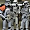
Well this is not something I would have thought that I would need to consider; however, recent experience has caused me to investigate this issue, here is what I have learned. When I started my ROTK build, the only supplier of ROTK gloves that I knew of was Imperial Boots (IB). IB calls these gloves Anthology Trooper Gloves (ATG) and they sell them for $69.90 plus shipping from the Philippines. I just checked their web site and they have reduced the price to $59.90 plus shipping. https://www.imperialboots.com/product/anthology-trooper-glove-shore-trooper/ So I purchased a set of the ATGs along with the T-7 boots for my ROTK build. When I received the gloves I tried them on to test the fit and the wrist immediately separated from the gloves in several areas. Additionally, the side seam separated as well. I assumed that I may have received a bad pair that were not stitched properly and decided to not contact IB about the issue since I had a sewing machine and I did not want to wait for the extended shipping from the Philippines. I re-stitched the gloves and did not give it another thought. I put the gloves on several times since then for application pictures and test fitting of the armor as I built it. My first troop in my ROTK was at DragonCon 2018. This was 4 months after I purchased the gloves. During the 3 hours I wore my kit, I observed that the gloves seams along the thumb had separated. I detailed all of this in my ROTK build here on FISD. https://www.whitearmor.net/forum/topic/44463-11b30b4’s-rotk-build/ In this picture you can see the re-stitched wrist (Yellow Circle), the freying of the elastic wrist from contact with Velcro (Red Cricle) I assume, and the separated seam on the thumb. So after DragonCon I first did a search to see if the gloves that they used for the screen version was a modified off-the-shelf glove. I was unable to discover any existing gloves that match what was used for the movie; however, I did find another manufacturer who sells a ROTK glove. The company is Endor Finders (EF) and they are located in the USA. EF sells a Rogue One Trooper Glove for $55.00 plus shipping. So I ordered a set and received them. https://www.endorfinders.com/costume-accessories/rogue-one-trooper-gloves Shortly after I ordered the glove from EF, I contacted IB about the issues I have had with the ATG gloves. After a few back and forth e-mails, IB sent me a new pair of the ATG gloves. I won’t say it was a painless experience but they did replace the gloves so there is that. I have held off doing this comparison until I received the replacement ATG gloves and now that I have them, it is now time to do this. At first look both gloves look almost identical. Honestly, I expected the gloves from EF to be the exact same as what IB sells. Once I got the EF gloves I quickly noticed the differences. As you can see the cuff on the EF gloves is longer although both gloves are the same size. The EF gloves fit a bit tighter but that is because they are lined on the inside while the IB gloves are not lined. Here is the palm and back of the IB glove. And this is the EF palm and back. A side by side of EF (left) and IB (right) Inside lining of the EF (Left) and no liner on the IB glove (Right). Inside the EF glove. Inside the IB glove. Wrist of the EF glove. Wrist of the IB glove. The EF glove with armor. The IB glove with armor. My observations: 1. The ribbed fabric used by each manufacturer is different. So I looked at some reference pictures from SW celebration. In this picture the glove fabric looks like the grid fabric used by EF. However, in these pictures, the fabric looks more like the ribbed fabric used by IB. So I am at a loss to determine which is correct. I suppose that both could be correct. 2. The wrist on the EF glove is fabric and not elastic. The fabric on the IB glove is elastic. 3. The EF glove is lined and fits like an Isotoner while the IB gloves are unlined and fit like Mechanix gloves. 4. The stitching quality appears to be better in the RF gloves while even the new IB gloves are poorly stitched. 5. The Velcor patches on the back of the EF gloves are opposite (One soft and one hard) while the Velcro patches on the back of the IB gloves are both soft. 6. The leather on both gloves looks to of similar type and quality and screen accurate. Conclusion: The EF glove seems to be a better product and is sold for a few dollars less than the IB glove. I have not trooped the EF glove as of yet, so my opinion may change once I get more experience with them but I doubt it. I hope that some of you find this information helpful. Happy trooping.5 points
-
You have your kidney upside down The notch goes on the bottom. Carry on3 points
-
Working on other items... Sent from my iPhone using Tapatalk2 points
-
Went back home a little early today and worked on it. BEFORE (L) / AFTER (R) New tubes decals applied too (Right picture).2 points
-
That´s the Stunt-configuration. Hero has four and as most people build for a Stunt, they had to remove the upper screws and fill in the holes in the belt (unless you changed the whole belt) ANOVOS listened and changed to the kit version which makes it easier2 points
-
I think that is enough decal removal for now. Now for the paint. Sent from my VK815 using Tapatalk2 points
-
If you want to have the ends on the TD removable you can wrap some tape around the end of the pipe and then place the heated caps on, once it's cooled down you can remove the caps, then the tape and the caps will slip on easily. Some add a dab of E6000 to secure them, I added a couple of angled ABS brackets to the insides of the end caps then ran elastic with Velcro on the ends to the brackets, can be a place to store some things, I normally carry my Working With Children Card in there in case I need to present it at an event (it's local law when you are with children that you hold a WWCC).2 points
-
I'll have to try that next time Sent from my LGLS992 using Tapatalk2 points
-
I am now officially TK-17529!!!2 points
-
Hi all, I'm Paul, I have been a member here for a while, but this is the first time I think I have contributed. Firstly I would like to say that the intention of this build is not to make a hyper realistic E-11 blaster, and I am aware more can be done in terms of detailing than I have done here to make a more accurate representation of an E-11. My goal was to make a reasonably accurate looking ANH E-11 which had the added benefit of an electronic light and sound system. Here is a video of the completed build which I did to talk about the build and demonstrate the electronics. I will start with a list of all the parts I have used and where they can be purchased. Doopy Doos Resin E-11 kit https://www.doopydoos.com/stormtrooper-e-11-complete-anh-e-11-blaster-kit-offer-2685-p.asp BlastFX electronic effects board & Mini Scope Display from TRamp. https://www.facebook.com/trooperamp/ Hegstler Counter box, Trigger assembly, Charging port assembly, & barrel LED mount from Lee McCormack - Shadow Defense Systems on Shapeways. https://www.shapeways.com/shops/shadow-defense-systems Power Cylinders from CSB Props on Shapeways. https://www.shapeways.com/product/ERH6MCTSC/power-cell-assembly-7-with-2-resistors?optionId=59449027&li=marketplace Hollow 1943 M38 scope kit from Bulldog Props. https://www.facebook.com/BulldogPropsJapan/ Various parts from Tino’s E-11 finishing kit including the scope rail and counter bracket. USB charging board. https://www.ebay.co.uk/itm/TP4056-5V-1A-Micro-USB-18650-Lithium-Battery-Charging-Board-Quality-1-2-5-10pc/163005239011?ssPageName=STRK%3AMEBIDX%3AIT&_trksid=p2060353.m2749.l2649 1000mAh Lithium Polymer battery. https://www.ebay.co.uk/itm/Conrad-Energy-Lithium-Polymer-Battery-3-7V-1000mAh-10C-with-BEC-Connector/122527159108?ssPageName=STRK%3AMEBIDX%3AIT&_trksid=p2060353.m2749.l2649 Black PVC tube, clear acrylic tube, & rare earth magnets. All purchased fro eBay. The only glue used throughout the build is Zap-A-Gap CA+ which I purchase from Amazon and Miliput was used as filler which can also be bought from Amazon. Spray paints are from Halfords, Clear coat and detailing paints are all Tamiya acrylics and Revell Aqua color, and the weathering washes are from the Mig range of model making products. My starting point for this build was the scope and mini scope display. I built the scope kit as per the instructions which come with the kit. I then drilled a 3mm hole in the underside of the scope just behind the front leg. The power cables for the mini scope display were then threaded trough this hole and the electronics boards slid into the body of the scope. I then used clear tape to secure the display to the red lens of the display kit, ensuring that the tape extended up the sides of the lens and making sure the display was centred on the lens. This was slid into the rear of the scope where the retaining ring inside the scope then presses against the tape securing everything in place. The clear lens from the kit the goes in on top of this and the scope lens retaining ring is screwed in to secure the whole assembly in place, making sure that the display is oriented correctly to the scope. Next I prepared the parts of the resin blaster kit. The counter box, scope, trigger and power cylinders from the kit were discarded as the would be replaced with alternative parts. The rest had any casting flashing removed, generally cleaned up and washed in soapy water. next I cut a hole in the receiver tube behind were the mag well casting will eventually be fitted. I marked the position of the mag well on the receiver and then marked out an area inside of this which still allowed for the mag well to be glued in place. the corners of the smaller area were then drilled out, and a Dremel with a router bit was used to create the opening. The receiver is actually quite thick as it has a PVC strengthening tube inside of the resin casting. I moved on to the trigger assembly next. A hole was created in the resin trigger group casting by drilling and routing with a Dremel once again. This hole houses the 3D printed trigger assembly, and needs to be snug, but not so tight as to restrict the trigger movement in any way. The trigger assembly was built up incorporating the trigger switch from the BlastFX unit. I opted at this point to cut the wires for the trigger switch in order to feed them through a small hole in the receiver, rather than having to make a larger hole to fit the switch itself through, which may need filling after assembly. I also fitted a small coil spring ( a cut down ball point pen spring) between the back of the trigger itself and the resin trigger group. This spring returns the trigger after it has been depressed. A hole was routed out in the back of the trigger group above the pistol grip where the rumble generator was fitted. Similarly the wires for the rumble generator were cut to accommodate easier wiring later on. Two 3mm holes were drill in the receiver for the 2 sets of wires to pass through, and then the trigger group was glued and screwed into place using Zap-A-Gap and self tapping screws. I chose the method of fixing as I want a very strong bond between the trigger group and receiver. The scope assembly was then fitted to the rail and counter bracket. The holes in the rail and counter bracket needed drilling out to take the screws which come with the scope. I ended up gluing these screws in place as the resin the scope is made from is quite soft, and I did not feel that the screws would hold for any length of time just by screwing them in. This assembly was then attached to the receiver in order to ascertain where the counter bracket would sit in order to place a 6mm hole behind it which would allow wiring access between the counter and the receiver. The scope and bracket were then removed and the front half of the counter was fixed to the bracket with some self tapping screws. A further 6mm hole was drilled through the bracket and counter to give access to the counter. I then cut a piece of 22mm diameter 3mm walled clear acrylic tube to length and slid it into the receiver until it sat where the barrel would normally be. The 3D printed LED end cap was assembled and the unit was then placed through the hole at the mag well, and placed over the end of the acrylic tube. The wires for the LED were once again cut to allow them to be routed back to the counter box. A length of 20mm black PVC tube was cut to fit inside the receiver to cover the charging handle slot so that the wiring in the receiver cannot be seen. This needs cutouts at each end to allow space for the wiring hole behind the counter bracket, and the charging board which sits at the end of the receiver behind the end cap. The Charging board and on/off/charge switch were assembled, and leads soldered on to reach back to the mag well opening. The main BlastFX board, display panel, speaker and selector switch where then all fitted into the 2 halves of the counter box, with the trigger, rumble unit and flash unit wires all fed out through the previously drilled 6mm hole. This hegstler box 3D print is a godsend if you are using the BlastFX system because it has been designed specifically for the components to all fit in. It has a cut out for the screen, a grill and mounting pegs for the speaker, and an assembly which creates the working reset switch, brilliant!!! As it is made for the BlastFX system though, it does have a 'BlastFX' logo where the Hengstler Eagle logo should be, so if that is important for you you may need to find a work around or alternative part. The corresponding ends of the cut leads were fed through the receiver and out of the 6mm hole behind the counter bracket. The cable ends were then rejoined by soldering them and heat shrink was used to cover them. Next the power lead from the main board was fed out of the back of the counter, and along with the power lead from the scope fed through the 6mm hole in the receiver and along to the mag well opening, where they were soldered to the appropriate leads from the battery connector and the charger/on/off switch. At this point the battery was attached and correct function of all the components confirmed, before the charger/switch assembly was glued into the back end of the receiver and all remaining cabling were fitted back into the receiver. I then effectively had a functioning blaster, except that the speaker was not working for some reason at this point. This was resolved shortly afterwards. The rest of the resin detail parts were then added. I also replaced the 2 screws at the muzzle with real metal knurled hex bolts. I also replaced the hex bolt in the end of the pistol grip with a real bolt too. Several other hex screws were used to replace resin cast parts. The end cap was fitted, and a section of foam was added inside. This foam pushes agains the end of the receiver and provides enough tension to hold the end cap securely in place so that it does not rattle around. The mag well and mag were hollowed out to allow the battery to sit inside. The mag well was then glued in place, and rare earth magnets were recessed into both the mag well and mag to keep the two together when the mag was inserted. The blaster was now ready for masking prior to paint. All parts to remain free from paint including the holes in the receiver which the clear tube can be seen through were masked off using masking tape and Blu Tak. The battery was removed. The front end of the scope was also removed to protect the front lens and preserve the metal finish of the screws which hold it in place. The blaster received 2 coats of Halfords grey plastic primer, which was allowed to cure for 24hrs. Then 2 coats of Halfords satin black were applied as a base colour. Once the black paint was touch dry I also added various bits of detail paint in Tamiya XF-16 flat aluminium, and X-31 titan gold. I also touched in any light spots in the black paint with Tamiya X-18 semi gloss black. I used a white wax crayon to highlight the lettering on the back of the scope. I also replaced all the parts I removed for painting, and unmasked enough to check that all the functions still work as they should (and they did this time). Next the blaster was dry brushed with the silver and the scope dry brushed with gold. This is to simulate ware and tear in the paint and finish on the gun. It is done by loading a small amount of paint onto an old paint brush (I find old and worn out ones work the best the more rough looking the better). Then most of the paint is brushed off. I use a folded piece of kitchen towel and just rub the brush on it until almost all the paint is gone, and the brush looks dry, hence dry brushing. Then just brush over the blaster and this will leave what little paint is left on any raised edges, corners and high spots which is generally where ware and tear occurs. Once the dry brushing has had enough time to dry, a wash of Mig ‘dark brown for green vehicles’ enamel wash was applied over the top of the dry brush weathering. This gives the blaster a more dirty look, and blends and softens the dry brushing a bit. When dry, this was then all sealed with a coat of Tamiya TS-80 flat clear. The clear coat seals in the weathering and gives the blaster a uniform finish. The final stages were to remove all the masking, and then hand paint areas inside the vent holes in the receiver which had missed paint due to the masking. I painted these is Revel Aqua Colour 08 black matt. The front of the hengstler box was given a very light brush coat of Tamiya x-18 semi gloss black, and the rear of the box was dry brushed in the same colour to try and give the look of the plastics used in the counters covers. There was then some very light dry brushing of the silver and gold paints again on areas where high levels of ware may occur just to bring out some of the highlights that had been dulled back by the earlier wash. And that completed the build. I would like to say a massive thanks to Paul Whitrow over at TRamp for his advice and encouragement, to Lee McCormack at Shadow Defence Systems for his excellent 3D printed parts which are superbly designed to just work with BlastFX, To Brian at BullDog Props for hid brilliant M38 scope kit and the advice on getting the right one for my needs, and to Tino for his fantastic detailing parts kit and scope rail. You all made this build a lot easier to pull off Guys thank you. Thanks for taking the time to read through this long post, I hope you enjoyed it. Paul1 point
-
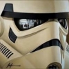
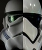
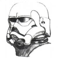
Prop store have an auction at the end of the month and one lot is a TLJ screen used helmet. https://propstoreauction.com/view-auctions/catalog/id/138/lot/28672/?url=%2Fview-auctions%2Fcatalog%2Fid%2F138%2F%3Fpage%3D20 Whilst none of us are likely to have the money to buy it, there's some amazing images as always so some excellent reference. See also these ANH stunt helmet and E-11: Hemlet https://propstoreauction.com/view-auctions/catalog/id/138/lot/28623/?url=%2Fview-auctions%2Fcatalog%2Fid%2F138%2F%3Fpage%3D18 E-11 https://propstoreauction.com/view-auctions/catalog/id/138/lot/28622/?url=%2Fview-auctions%2Fcatalog%2Fid%2F138%2F%3Fpage%3D181 point
-
Mineral spirits have worked for me on some excess paint, great for Humbrol paint and also works on some glue like JB weld.1 point
-
Firstly a belated congrats on your approval. Your build has become one of my go-to’s for my own glacial speed build [emoji1] What did you use to remove the decals? Also, DLT-19? Going HWT? Sent from my DH77 using Tapatalk1 point
-
I've had good luck with mineral spirits for cleaning up excess glue. Also, it won't melt the ABS like acetone would. But it will remove any paint already there, so keep it away from any paint or decals you want to keep.1 point
-
Haha! Good catch. Thanks... it was kind of a spur of the moment let’s see if I can get this thing working type of deal Sent from my iPhone using Tapatalk1 point
-
I agree. Overall you're mostly there. The shoulders need some attention to get them to line up properly and most of all reliably. We raise and lower our arms a lot and if your bell keeps shifting around you're quickly gonna become an unhappy trooper. Get that belt up and secured where it belongs should solve that bit. You need to get that butt-ab strap in there to fix your back screen door Once you sort that stuff out post some new photo's from head to toe. Maybe against a neutral wall. You're almost ready to miss your target Trooper!1 point
-
Testing the internal strapping. Kind of exciting. I do see why snaps are preferred. I need longer velro straps in for attaching in some places. I might add a few snaps on the front at some point.1 point
-
I never used those measurements but that’s the general Idea. All the belts go together basicly the same way, what differs is what type of fasteners one uses. The thing to watch is the hight of the ammobelt and not to place the snaps to close to the raised edges on the ab. The method to get the belt to stay snapped in is to first set the middle (I used single cap rivets), snap the canvas to the ab, bend the ammobelt and mark were to put the outer holes through the ammobelt (you drill those holes beforhand) If you like some visual aid feel free to check my Hero-build1 point
-
Looking good Rat, nice job so far.1 point
-
How was the con? I saw Jon Campling (Death eater in HP Deathly Hallows) tweeting about it going up as he's in Eastbourne. It was a bit of a trek so I didn't go but it's not that bad if it's a good event.1 point
-
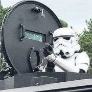
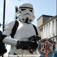
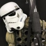
Thank you for the kind comments and support chaps I appreciate it. Here are a couple of pics of the DLT-19 on its first deployment. These were taken at WynterCon, which is a con here in my home town of Eastbourne, UK. As you can see it takes place in a huge big top!! Whilst I am a member of 501st (Tusken Raider) I don't troop with 501st as a TK, so this troop was done as a member of the Imperial Outlanders (that's the badge on our pauldrons). I am working this set up into a 'clean' Heavy Weapons Trooper, so its still a work in progress, bits still to change and add. Its clean because then I can also troop the armour as a standard TK too. Paul1 point
-
The traps will more or less wipe off with some enamel thinners. I used humbrol. The hard paint to remove is the vocoder which really wasn't needed in hindsight.1 point
-
Mine was a few spots around the circumference with a bit more to hold the ears down. Was just a case of slow and stead to get it apart. Don't be tempted to use CA remover, it will melt the ABS.1 point
-
Grrr. You're right. It is just a little low. 5mm higher would be nice. This is a shot wearing the armor. Sorry for the poor quality bathroom lighting. :-) It's pretty close. Think it will be an issue? I guess I could leave the snaps on the torso and take the belt apart instead. I could try to patch the holes and try to set the snaps in the belt 5mm lower to raise the belt up. Mark1 point
-
You can loop a piece of elastic through the top loop on the boot, then add a snap to it and another on a snap plate to the inside of the shin. Just helps when you bend your knees to keep the shin down on your boot, also stops rotation1 point
-
Yer and what did you expect them to say I know A LOT of people who have pulled out. How many cancelled runs of helmets and armor have they done now, anyone remember the Death Trooper, they don't make anything unless there is money in the bank and looks like that money is quickly running away.1 point
-
I was really happy that they stopped building the belts and shipped them in kit form. Sent from my VK815 using Tapatalk1 point
-
Ok belt edges angled now. Blue buttons repainted. They're lighter in person, but picture still looks dark. Sent from my SM-G955U1 using Tapatalk1 point
-
Copy that, thanks! Sent from my MSE-6 droid using Tapatalk1 point
-
Nope they just sit on the top of the boots. Some add snaps or velcro if they have a problem with them trying to ride up though. Sent from my VK815 using Tapatalk1 point
-
I canceled a month ago and am still waiting for the check.1 point
-
I spoke with a supervisor and he stated there have actually been only a very few cancellations. Remember it’s not just us in the 501st buying them. As far as shipping they estimated to complete all shipping by April 2019, not beginning in April was my understanding.1 point
-
Awesome work Erik! Congrats!1 point
-
The Alpha Beta kits join on the top edge of the back plate, there is a strengthening piece under neath with glued to both. Because of the join it must then be filled and painted, something I asked Anovos about multiple times when they said the new kits wouldn’t need painting, could never get a straight answer on how they achieved that and what they changed the only reply was “they won’t need paint”. If it is indeed the hinge system on the shoulders then it would need gluing and filling so paint would need applying. You can only vacform on pieces that have an outwards tapper, you can’t pull down and onwards or you will never get the pulled piece off the mold. Hence they came up with the join hinge (if in fact it is a hinge). You would think with ex 501st members involved in their business that they would know about the CRL’s and how costumes need to replicate those on screen. You would also think with all the issues will late delivery on the beta kits that they would of learned but no, their customer service is even worse. im not sure why they won’t come clean and inform everyone exactly what the hold up is and when they will actually be delivered. You can’t keep stringing people along, they will only take so much. i can see Anovos having a sale on these kits once they finally become available, by the sounds of all the cancellations they’ll be stuck with a lot of them.1 point
-
Great weathering techniques! Love the details!1 point
-
Paul, please don't go. Your DLT-19 is what I hope to fashion mine after. I am even looking into getting the same parts, which is a little harder being that I am in the USA. Many of us here use posts like yours as a guide and even though you may not always get feedback, the hard work is appreciated and encouraging. Also... Action Man!1 point
-
Nice blaster Scalawag! As someone who has owned four real MG-34s over the past 30+ years, let me say that you really nailed the weathering on this. It looks completely authentic to me. Unfortunately even though I know the MG-34 very well, I have only a superficial knowledge of the DLT-19 conversion, but it looks like you've also done a stellar job of updating those details as well! Please don't be put off by occasional brief comments here, this is a great place to share your work and find helpful info. I can't begin to describe how much help I've been able to source here. Also remember that this is a world-wide site, and mannerisms of speech and syntax can vary greatly from country to country. In some places it can be considered quite normal to make brief comments that may seem terse in other locations or cultures, but are not actually intended to be rude. In any event I just wanted to congratulate you on a fantastic piece of work and I hope that you will continue to post your projects here. You might like to checkout my steel E11 blaster project thread, you'll find the link in my footer below.1 point
-
Parquette, I agree and have made plans to get some of the Vac Formed ROTK stuff that NaturalBorn and Head Shot Props are working on. BTW, I just got a black Series helmet so is there any change you can fix the pictures on your how to modify thread? Most of the pictures of what you have done to modify the helmet are not showing up. Update, Ok, the repair has commenced. First, I found some white craft foam that is slightly wider than the inside of the drop boxes. I am confident that the drop boxes are causing all the damage to the top of the thighs. I cut and glued some of this foam inside the drop boxes and this should fix this. I will add the Velcro straps soon. Next, I glued a piece of HIPS to the inside of the back plate to fix a crack. I still need to sand this and add more Velcro to this part. With the cracking of the shoulder strap, I have decided to attempt to make some rubber or foam shoulder straps. First, I needed to make a flat version of the shoulder strap. I used some ¼” plywood and I cut a lot of these ½ rounds then glued them in place on the plywood. I framed out a box and glued the shoulder strap inside. Then I filled it with Smooth-on Rebound 25. I would have used OOMOO 30 but the OOMOO I had, went bad and solidified. So Rebound -25 is a bit thicker but its still silicone. Once the mold cured, I pulled it out of the frame and removed the shoulder strap. So far it looks good. Well that’s it for the update so far. Thanks for the interest.1 point
-
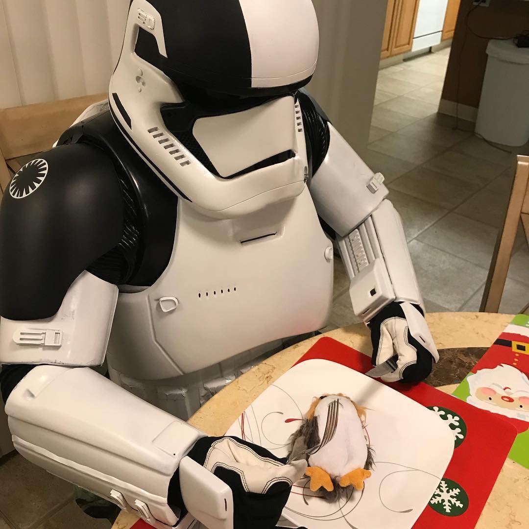
Due to life being the pain it can be - I don't get to see "The Last Jedi" til I troop on Sunday. SO before I go internet dark to try and avoid as many spoilers as I can, I thought I'd have a little fun showing off the progress I've made so far. Yes, I'm sitting, and no I haven't built any part of my armor below the chest plate yet! Merry Star Wars Eve, everyone!
 1 point
 -
Looks like a million bucks,,, alot of hard work that paid off nicely.....1 point