Leaderboard


Popular Content
Showing content with the highest reputation on 08/10/2018 in all areas
-
Wow Paul! What a work of art. Without any doubt, this is a very special blaster. Mission absolutely accomplished. Many builders (including me) spent much time in the recreation of fine details. During trooping, they are simply overlooked, as there is so much more to see... With this build, you focussed on the right kind of detail, because 2 displays, the sound and the LEDs in the barrel are hard to overlook. Once you start trooping, I guess many people will be fascinated by your blaster. Gotta go now. Feeling the need to build a new E-11 again...3 points
-
The hight of the shins are as they should, I just posted on another thread you got that I would trim them but I ment circumference so we are clear on that If fitted correctly the shins will dig on the boot but not so much it can do any real damage, wear and tear is to be expected and in my opinion ads to the Stormtrooper-look. If you want you can protect them by adding soft velcro on the inside of the shins2 points
-
I have indeed used the boiling method for small parts, also for my 2 tie costumes. No idea how to apply it to the butt plate indeed. So trying the snaps more to the edge first. it feels flexible enough indeed.2 points
-
Guys, the worst that could have happened has happened - my girlfriend and her Imperial Bridge Crew costume got approved before me :( well, I guess the approval process takes longer because the TK is a more complex costume.. I'm checking my mailbox about twice an hour right now, and I hope it won't take much longer :) Also I have decided that I want to follow @CableGuy's path and will apply for the Imperial Attaché programme for my region (after EIB and Centurion, of course) which I think will be great fun, and since I have managed to build my very own armor (hopefully up to Centurion as well) I guess I'll also be somewhat qualified... I'll keep you guys updated!2 points
-
The last worktime has been a mix of fails and success. Every time I start working I always think that I have to strictly plan my build, from inside to outside, from top to bottom or front to back... But seems virtually impossible. Lack of materials, laziness or any recent read of some of the awesome builds here in FISD makes me keep on with my chaos in order, or maybe order in chaos. Not talking about the outgrowing OCD, as a modeller/ hobbyist I DO really like detail, and maaaaany of your builds aggravate my mental illness (LOL) I wanted to add detail to the front sight, mainly the setting hex screw. Started drilling manually, finished badly. New try, don't give up. Use the broken one as a template (laziness, I have the templates on my tablet, but I was listening to music, The Cult, didn't want to pause it ) Uncountable fails later, I gave up. But, I opened a beer and the fails seemed a little less discouraging. This piece is made from a 5mm square wood stick, a sugar cotton one, don't know if it's correct saying that way. Very soft (good to sand/file, bad to drill) You can see in the pics what I told you about my crazy way of working. I always spread stuff over the table, but I don't tidy up until the end. Having failed in detailing the front sight, and before cursing again, I started one of the parts that I feared the more: rear end cap. I've used a 40 mm ID "cap", that's how it's called here, like a female lid, sorry if doesn't make sense. Drilling, tapping with M6 tap, use the M6 hex screw from the muzzle or grip and a M6 nut. What's that for? You can see I didn't lie with the beer... I want to introduce all Imperial troops my fancy guetto mill... Sandpaper, file, knife and lot of turns ( and heat, be careful with your hands ) and I got this Im really happy with the results, easy, fast but...lots of PVC shavings all around, not really clean, but it's really worth it. Two minutes of sweeping for a rear cap!!! Waiting for your thoughts and comments. Cheers.2 points
-
@gmrhodes13 definitely adding the foam. My first pre approval fit scratched paint so I painted those spots again and now will add some foam. The Velcro didn’t quite pad enough. Im doing that and then getting my approval pics tonight. Hoping to get at least some temp approval for a troop next week. So get ready for some pretty pictures.2 points
-
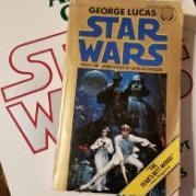
Hi all, I'm Paul, I have been a member here for a while, but this is the first time I think I have contributed. Firstly I would like to say that the intention of this build is not to make a hyper realistic E-11 blaster, and I am aware more can be done in terms of detailing than I have done here to make a more accurate representation of an E-11. My goal was to make a reasonably accurate looking ANH E-11 which had the added benefit of an electronic light and sound system. Here is a video of the completed build which I did to talk about the build and demonstrate the electronics. I will start with a list of all the parts I have used and where they can be purchased. Doopy Doos Resin E-11 kit https://www.doopydoos.com/stormtrooper-e-11-complete-anh-e-11-blaster-kit-offer-2685-p.asp BlastFX electronic effects board & Mini Scope Display from TRamp. https://www.facebook.com/trooperamp/ Hegstler Counter box, Trigger assembly, Charging port assembly, & barrel LED mount from Lee McCormack - Shadow Defense Systems on Shapeways. https://www.shapeways.com/shops/shadow-defense-systems Power Cylinders from CSB Props on Shapeways. https://www.shapeways.com/product/ERH6MCTSC/power-cell-assembly-7-with-2-resistors?optionId=59449027&li=marketplace Hollow 1943 M38 scope kit from Bulldog Props. https://www.facebook.com/BulldogPropsJapan/ Various parts from Tino’s E-11 finishing kit including the scope rail and counter bracket. USB charging board. https://www.ebay.co.uk/itm/TP4056-5V-1A-Micro-USB-18650-Lithium-Battery-Charging-Board-Quality-1-2-5-10pc/163005239011?ssPageName=STRK%3AMEBIDX%3AIT&_trksid=p2060353.m2749.l2649 1000mAh Lithium Polymer battery. https://www.ebay.co.uk/itm/Conrad-Energy-Lithium-Polymer-Battery-3-7V-1000mAh-10C-with-BEC-Connector/122527159108?ssPageName=STRK%3AMEBIDX%3AIT&_trksid=p2060353.m2749.l2649 Black PVC tube, clear acrylic tube, & rare earth magnets. All purchased fro eBay. The only glue used throughout the build is Zap-A-Gap CA+ which I purchase from Amazon and Miliput was used as filler which can also be bought from Amazon. Spray paints are from Halfords, Clear coat and detailing paints are all Tamiya acrylics and Revell Aqua color, and the weathering washes are from the Mig range of model making products. My starting point for this build was the scope and mini scope display. I built the scope kit as per the instructions which come with the kit. I then drilled a 3mm hole in the underside of the scope just behind the front leg. The power cables for the mini scope display were then threaded trough this hole and the electronics boards slid into the body of the scope. I then used clear tape to secure the display to the red lens of the display kit, ensuring that the tape extended up the sides of the lens and making sure the display was centred on the lens. This was slid into the rear of the scope where the retaining ring inside the scope then presses against the tape securing everything in place. The clear lens from the kit the goes in on top of this and the scope lens retaining ring is screwed in to secure the whole assembly in place, making sure that the display is oriented correctly to the scope. Next I prepared the parts of the resin blaster kit. The counter box, scope, trigger and power cylinders from the kit were discarded as the would be replaced with alternative parts. The rest had any casting flashing removed, generally cleaned up and washed in soapy water. next I cut a hole in the receiver tube behind were the mag well casting will eventually be fitted. I marked the position of the mag well on the receiver and then marked out an area inside of this which still allowed for the mag well to be glued in place. the corners of the smaller area were then drilled out, and a Dremel with a router bit was used to create the opening. The receiver is actually quite thick as it has a PVC strengthening tube inside of the resin casting. I moved on to the trigger assembly next. A hole was created in the resin trigger group casting by drilling and routing with a Dremel once again. This hole houses the 3D printed trigger assembly, and needs to be snug, but not so tight as to restrict the trigger movement in any way. The trigger assembly was built up incorporating the trigger switch from the BlastFX unit. I opted at this point to cut the wires for the trigger switch in order to feed them through a small hole in the receiver, rather than having to make a larger hole to fit the switch itself through, which may need filling after assembly. I also fitted a small coil spring ( a cut down ball point pen spring) between the back of the trigger itself and the resin trigger group. This spring returns the trigger after it has been depressed. A hole was routed out in the back of the trigger group above the pistol grip where the rumble generator was fitted. Similarly the wires for the rumble generator were cut to accommodate easier wiring later on. Two 3mm holes were drill in the receiver for the 2 sets of wires to pass through, and then the trigger group was glued and screwed into place using Zap-A-Gap and self tapping screws. I chose the method of fixing as I want a very strong bond between the trigger group and receiver. The scope assembly was then fitted to the rail and counter bracket. The holes in the rail and counter bracket needed drilling out to take the screws which come with the scope. I ended up gluing these screws in place as the resin the scope is made from is quite soft, and I did not feel that the screws would hold for any length of time just by screwing them in. This assembly was then attached to the receiver in order to ascertain where the counter bracket would sit in order to place a 6mm hole behind it which would allow wiring access between the counter and the receiver. The scope and bracket were then removed and the front half of the counter was fixed to the bracket with some self tapping screws. A further 6mm hole was drilled through the bracket and counter to give access to the counter. I then cut a piece of 22mm diameter 3mm walled clear acrylic tube to length and slid it into the receiver until it sat where the barrel would normally be. The 3D printed LED end cap was assembled and the unit was then placed through the hole at the mag well, and placed over the end of the acrylic tube. The wires for the LED were once again cut to allow them to be routed back to the counter box. A length of 20mm black PVC tube was cut to fit inside the receiver to cover the charging handle slot so that the wiring in the receiver cannot be seen. This needs cutouts at each end to allow space for the wiring hole behind the counter bracket, and the charging board which sits at the end of the receiver behind the end cap. The Charging board and on/off/charge switch were assembled, and leads soldered on to reach back to the mag well opening. The main BlastFX board, display panel, speaker and selector switch where then all fitted into the 2 halves of the counter box, with the trigger, rumble unit and flash unit wires all fed out through the previously drilled 6mm hole. This hegstler box 3D print is a godsend if you are using the BlastFX system because it has been designed specifically for the components to all fit in. It has a cut out for the screen, a grill and mounting pegs for the speaker, and an assembly which creates the working reset switch, brilliant!!! As it is made for the BlastFX system though, it does have a 'BlastFX' logo where the Hengstler Eagle logo should be, so if that is important for you you may need to find a work around or alternative part. The corresponding ends of the cut leads were fed through the receiver and out of the 6mm hole behind the counter bracket. The cable ends were then rejoined by soldering them and heat shrink was used to cover them. Next the power lead from the main board was fed out of the back of the counter, and along with the power lead from the scope fed through the 6mm hole in the receiver and along to the mag well opening, where they were soldered to the appropriate leads from the battery connector and the charger/on/off switch. At this point the battery was attached and correct function of all the components confirmed, before the charger/switch assembly was glued into the back end of the receiver and all remaining cabling were fitted back into the receiver. I then effectively had a functioning blaster, except that the speaker was not working for some reason at this point. This was resolved shortly afterwards. The rest of the resin detail parts were then added. I also replaced the 2 screws at the muzzle with real metal knurled hex bolts. I also replaced the hex bolt in the end of the pistol grip with a real bolt too. Several other hex screws were used to replace resin cast parts. The end cap was fitted, and a section of foam was added inside. This foam pushes agains the end of the receiver and provides enough tension to hold the end cap securely in place so that it does not rattle around. The mag well and mag were hollowed out to allow the battery to sit inside. The mag well was then glued in place, and rare earth magnets were recessed into both the mag well and mag to keep the two together when the mag was inserted. The blaster was now ready for masking prior to paint. All parts to remain free from paint including the holes in the receiver which the clear tube can be seen through were masked off using masking tape and Blu Tak. The battery was removed. The front end of the scope was also removed to protect the front lens and preserve the metal finish of the screws which hold it in place. The blaster received 2 coats of Halfords grey plastic primer, which was allowed to cure for 24hrs. Then 2 coats of Halfords satin black were applied as a base colour. Once the black paint was touch dry I also added various bits of detail paint in Tamiya XF-16 flat aluminium, and X-31 titan gold. I also touched in any light spots in the black paint with Tamiya X-18 semi gloss black. I used a white wax crayon to highlight the lettering on the back of the scope. I also replaced all the parts I removed for painting, and unmasked enough to check that all the functions still work as they should (and they did this time). Next the blaster was dry brushed with the silver and the scope dry brushed with gold. This is to simulate ware and tear in the paint and finish on the gun. It is done by loading a small amount of paint onto an old paint brush (I find old and worn out ones work the best the more rough looking the better). Then most of the paint is brushed off. I use a folded piece of kitchen towel and just rub the brush on it until almost all the paint is gone, and the brush looks dry, hence dry brushing. Then just brush over the blaster and this will leave what little paint is left on any raised edges, corners and high spots which is generally where ware and tear occurs. Once the dry brushing has had enough time to dry, a wash of Mig ‘dark brown for green vehicles’ enamel wash was applied over the top of the dry brush weathering. This gives the blaster a more dirty look, and blends and softens the dry brushing a bit. When dry, this was then all sealed with a coat of Tamiya TS-80 flat clear. The clear coat seals in the weathering and gives the blaster a uniform finish. The final stages were to remove all the masking, and then hand paint areas inside the vent holes in the receiver which had missed paint due to the masking. I painted these is Revel Aqua Colour 08 black matt. The front of the hengstler box was given a very light brush coat of Tamiya x-18 semi gloss black, and the rear of the box was dry brushed in the same colour to try and give the look of the plastics used in the counters covers. There was then some very light dry brushing of the silver and gold paints again on areas where high levels of ware may occur just to bring out some of the highlights that had been dulled back by the earlier wash. And that completed the build. I would like to say a massive thanks to Paul Whitrow over at TRamp for his advice and encouragement, to Lee McCormack at Shadow Defence Systems for his excellent 3D printed parts which are superbly designed to just work with BlastFX, To Brian at BullDog Props for hid brilliant M38 scope kit and the advice on getting the right one for my needs, and to Tino for his fantastic detailing parts kit and scope rail. You all made this build a lot easier to pull off Guys thank you. Thanks for taking the time to read through this long post, I hope you enjoyed it. Paul1 point
-
Trooper Info Name: Christopher Bailey Forum name: nosferachew Garrison: Connecticut Garrison Legion Number: 66402 501st Legion Member Page: http://www.501st.com/members/displaymemberdetails.php?userID=22859 Height: 5' 8" Weight: 165lb Costume Information Armor: AP Authentic Props Helmet: AP Authentic Props Blaster: SE-14r by Shawn Morgan Boots: TK Boots Canvas belt: TKittell Hand Plates: My Wife @Alay Neck Seal: Darman Pouches: Anthony Bailey from MEPD (no relation!) Backpack: Homemade Pauldron: Trooperbay This is the same base costume I used for my ANH Stunt Centurion build, which is available for reference here: CRL Used: https://databank.501st.com/databank/Costuming:TK_hwt I hope to take this to Centurion, so any suggestions related to making it Centurion level are highly appreciated! Full Gallery on CTG Boards: https://ctg501.com/community/index.php?/gallery/album/30-heavy-weapons-trooper/ Front: Back Left Right: Action Shots Bucket Off Cod Rivet Ab Buttons Squishy Silicone Hand Guards "Movie-Accuracy" right side ab male snap Male Snaps in Posterior MP 40 Pouch Details (all are same) Bridge Elastic Backpack Closeups Knee Belt Rivets Sniper Knee Helmet Closeups/Details Weathering I tried to intentionally go light on the weathering and instead of doing many "blast point" scores instead let the scraps and wear spots on my armor from troops catch the black powder. Interior Strapping SE-14R Finally, screwing around with my Union Jack Pauldron. Need to represent as the only Brit in the CTG I greatly appreciate any critiques and for the Detachment staff for taking the time to review my submission! Thanks! ~Christopher1 point
-
Fourth try writing the same, I hope this time it works flawlessly. If not, I'll post without ( by now the damnit )Tapatalk.... Cursing mode OFF. I seriously doubt if writing the long post version or the short one, I've make both in the last three hours... Second scratchbuild try, first a Sandtrooper helmet (waiting for answers for where to post about it) and now working in a E11 ANH blaster. Very very low budget (you can say none for this build), very slow work/updates (mainly after work time) but high times working on it with my limited modelling/painting skills. I'm really trying to not purchase any part of this build, at least not anything previously built/ cast/ 3D All of you will know about the materials used in this build, 40 mm OD PVC pipe / tube, plasticard/polystyrene (Evergreen), plywood, aluminum and several other "ghetto resources" that I'll try to show you very soon. I'm really scared about pictures, I won't like to lost my pics and words again. First picture, fuxxxng Tapatalk suddenly stops and started cursing in languages I don't even speak... I think I'll post this, and I'd try to upload pics later. Siesta time's coming, near 40°C just now here in Spain... Thanks. Sent from my SM-T365 using Tapatalk1 point
-
Well...not to sure what he meant, I can`t really see any return edge to clean up so it`s possible he was talking about evening out the offset...but best to have him answer that1 point
-
Aha (meaning I´ll go check)1 point
-
I would NOT trim...leave as is...worry about the digging later Sent from my iPhone using Tapatalk1 point
-
Ok, I will go with this for now. Once I complete them, I may need to trim around the bottom - I don't like how they are digging into the boot. But, I won't make them any shorter as of now. Hey, the less trimming I have to do anymore, the better!1 point
-
Thanks!1 point
-
Quite possible. Now that I'm essentially finished minus the few adjustments I can focus on my blaster for that EIB and Centurion. Sent from my VK815 using Tapatalk1 point
-
Oops didn't noticed the post after Joseph's! Looks like you're already ahead of me on that! See ya at Centurion soon?1 point
-
You look very good! Joseph hit what I noticed. Only other thing... your belt is a bit long and that extra "flap" after the detonator might snag you on submission. I'd shorten up the belt a bit if you are able to, or hold down that extra bit with some velcro. Good luck!1 point
-
I still need to do the strap within the shoulder bell, around the bicep. the strapping between bicep and forearm is in place and I am actually planning to shorten the one on the left a little bit to pull my forearm up a tiny bit more. The idea of the strapping more to the tips of the butt plate sound like a very very much more attractive idea than changing the full shape indeed If I don't have to screw around with boiling water I'd rather not. going to investigate that right now! as for the height of the biceps, the right one is a bit more tight around my arm than the left, so might also be that when dressing I shoved one higher than the other.1 point
-
Looking good though I'm lot entirely convinced boiling is the best or safest solution. Like Swede mentioned adding connecting straps in the corners would achieve the same result. Another note, you may need to drop the right bicep, the left side appears to be hanging lower. Also, I believe you mentioned connecting the forearms to the biceps, doing that would definately help the gap between in that area.1 point
-
Shoulders look great RS armor is very flexible so for the butt plate you could try to move the strapping to the ends and also make them thighter before you go the hot water route.1 point
-
Come on, I get a pass this month right? Sent from my iPhone using Tapatalk1 point
-
Good Luck with approval! All easy fixes.1 point
-
Sorry two more... absence of return edge on my forearms1 point
-
Thank you for the tip. I will look into it. Sent from my iPhone using Tapatalk1 point
-
I have not. I’ve been using Ukwraths build as my references. Any suggestions for good ones? Sent from my iPhone using Tapatalk1 point
-
I just ordered one off of Amazon. It will arrive today sometime. Sent from my iPhone using Tapatalk1 point
-
Thanks Tony so far seems positive with just a couple of small fixes for down the road. Sent from my VK815 using Tapatalk1 point
-
Good luck Rat, see you on the other side.1 point
-
Hi everyone! It’s been a while, but back with an update. Last weeks have been crazy, and finally some time to post an update. I have made some substantial progress, at least it feels like it. It feels like my house exploded, blue tape and clamps everywhere, not to mention the lovely smell of e6000. Also found out that snaps are perfect as a cat toy… found at least 15 of them underneath my couch. Those bastards! For now, I left the bucket for what it is, and started to work on the other parts. Did another test fitting, now with most of the trimming done, it felt like armor! After the fitting couldn’t wait to start gluing the cover strips. Again spend hours and hours on this site for the best tips and tricks. So thankful for all the insights! Thanks awesome troopers!! Here’s a little photo update with some questions at the end. at the end. Belt The belt is almost ready, need to add the drop boxes: Thermal Detonator Also almost ready, everything has got the right size now, but searching for the right screws. Once I have them I can assemble everything Handguards Glued the flexible guards to the rubber gloves and added straps to the abs ones for my nomex trooping gloves. Butt Added the 2 male snaps and the strapping Shoulders, Biceps and Fore arms They are all now the right size and gluing of the cover strips is done. Currently working on the strapping. Shins They have the right size now, glued the front, hopefully today the back with velcro Thighs Fitting is now also right, front is not curing from glue, looking forward how they turn out so I can do the back tomorrow. Also created the nylon snapplates with tandy line 24 snaps – glue and clamps it is now. And one for the laughs Just gotta love the blue tape. Hope to get better test fitting photo's later on Getting somewhere! Feedback is very much appreciated! Few questions that would help me with moving on: - Having a hard time to keep the box and the inner box lined up in a good way. The outside is 15mm and the inner box 12 mm, but can’t make them fit like I would like them to have. Any suggestions how I can improve this? I guess lots of sanding? - I’ve noticed my curves (yaay female) are bit different then the armor allows. Thinking of cutting the ab in two, so separating the cod. In this way I can move the cod up a bit, to get some more movement. I’m waiting until the strapping of the total armor is done to make sure this is what I want to do, but is there any advice you can give if I want to go ahead with this? Any females out there with the same experience? - The TD screws---Whoa never thought looking for the right screws are so hard, turns out they are not an easy find in The Netherlands. I found these ones in my dads garage, would they do the trick? Thanks for reading and stay awesome!1 point
-
Agreed with Joseph's points! Your canvas belt looks a bit long too.1 point
-
Well, Joseph, as usual, nailed all points. Looking forward to your EIB application.1 point
-
Your fine trooper! Your a true TK as in we always miss I thought we had almost similar titles so I thought I'd double check. No harm no foul. Still jealous over that liner in your tote....I just have my kit go in with blankets covering the sides1 point
-
Scratch builds always put a smile on my face. I really like the individual approaches. Keep it up.1 point
-
So got pictures done and submitted for pre-approval. Well see how it goes. Sent from my VK815 using Tapatalk1 point
-
I’m glad you found this useful and I hope that some of the ideas from the build are indeed useful when you come to do your own. Brian’s scopes are brilliant, and do lift the build. They are very reasonably priced too for the level of detail you get with them. Enjoy your own build as much as I enjoyed this one, and just ask if I can help with anything. Paul1 point
-
Finally back at it after a week away. Then that is what I’ll do. Now I just need to ABS paste this into oblivion. Another point of concern. Will this discoloration in the ABS paste affect approval? I made the mistake of sanding without taking the tape all off and some of the tape color seems to have absorbed into the paste. It’s not super noticeable but I still am beating myself up over it. Sent from my iPhone using Tapatalk1 point
-
Good job cleaning those teeth up. Just a curious question do you mean to post in this build thread or do you mean to add to yours? It doesn't bother me one bit if you want to add to mine1 point
-
A little more progress: the second bicep is completed and the second forearm is well on its way. This forearm seemed to have a lot more tension/resistance going together for some reason even though it's the exact same as the other side, so I'm letting it cure for a while longer than usual just to be on the safe side. Then I'll put the inner strips in immediately after. And I'm already plotting another future build (on top of the Anovos FOTK a lot of us are waiting on)... Addicted or glutton for punishment, I'm not sure which yet. Maybe both.1 point
-
Thank you, like you we learned from those that came before us. Troopers Helping Troopers1 point
-
Hi there Paul, Great to see your complete progress with ample description here on FISD - I did come across your fb posts being a member of the BlastFX builders fb group myself. I'm glad you have Brian's scope - must be such a treat to marvel at the workings of the BlastFX scope component inside this scope! I will make due with a hollowed doopydoos version with Tino's completion set add-ons myself when I get to that stage... ...I will prepare a cup of coffee ahead of time before studying your posts - thanks for the thoroughness!! cheers!1 point
-
More progress to posts - this time on the bayonet lug: I'm part way through with enhancing the doopydoos bayonet lug nut for a circular base. I measured it at 12mm in diameter. Plasticard was used and it will be padded with green stuff on the bottom of it. The cured green stuff will be sanded down to follow the curvature of the receiver tube before install. cheers!1 point
-
A million thanks to you Tino for following through with those dimensions - they've helped me measure accurately for my doopydoos fitted version of the spring cup. I've converted the real dimensions you've given, by doing a relative calculation to obtain an accurate length for my version of the spring cup. Here I precision measure my spring cup to 23mm in length and cut evenly using a pipe cutter. You're making total sense to me Tino - I gathered that was how the spring cup functioned relative to the bolt but now with you're description, I understand it fully. I can now make an informed decision on how close I can get it to function like the real deal. The mechanism of my ROTEB will need to work like this: My outer, larger spring pushes against the end of my 20mm OD plastic tubing. Again, your completion set that came with an adequate wire gauge to form the spring and plastic tubing at the correct OD, really helped! As for my version of the spring cup, I will see to hollow it through, with a smaller inner diameter on the smaller end. I will insert a spring (OD 15mm) into the larger opening of the spring cup. Hopefully, with my spring cup getting narrower, the spring will stay in place. If not, I'll have to use E-6000 to make this happen. Also, a plastic piece will be used at the other end of this smaller spring to keep it in place. This follows somewhat SMG references but modified because I need to accommodate BlastFX wiring. For how my bolt will function in pulling back on the charge handle, the spring cup will not retract into the bolt. The only way it will retract into the bolt is if the cup gets pushed by the support piece at the end of the large spring...I can live with that! [emoji6] Have a terrific summer afternoon everybody - more updates to come soon!1 point
-
Some FB groups that aren't focused on accuracy and also aren't interested in referring people here think they have all the answers Sadly nobody has all the answers however, the collection of very talented builders that can be found here will get you going in the right direction and help maintain that. Without proper guidance people are more apt to head down the wrong path resulting in poor quality builds.1 point
-
Great work, Paul. Glad you posted it here as well as the FB pages. [emoji1303] Lovely use of Brian’s scope and Paul’s electronics. Looks like a brilliant blaster :-) Dan1 point
-
Out of words. Waiting eagerly (drooling of course) to see the finished replica. Astonishing work man. Wish I had the money... Keep up with the good work! Let another one counting pieces, we want more updates! Cheers from Spain.1 point
-
I used in no particular order Lexan scissors until the handle broke than I used tin snips Utility knife for straight cuts using a metal yard stick as a guide Dremel with sanding wheel for smoothing things out.1 point
-
Darthcue, Bulldog44, DEVOLVER and everyone else who has congratulated me, thank you and I appreciate all your comments. So EIB is under my belt and I have submitted my application for Centurion, fingers crossed. https://www.whitearmor.net/forum/topic/45367-tk-20980-requesting-rotk-centurion-status/1 point
-
KABOOM! And if my head was not inflated enough, there were no recommendations to fix anything or do anything different for Centurion. I am totally speechless since I know and see all the issues with my kit but I guess that is always the case with people who seek to do their best and are never completely happy with the results. Don't get me wrong, I do love my kit and I am very pleased with how it turned out but there are things I would like to fix on it. I also realize that I can get stuck in a cycle of fix this or that and never finish the kit.1 point
-
Open to thoughts and comments. Please note there's almost nothing glued/fixed in place yet, everything is dry mounted to show how it looks. Be patient with me, totally new to Tapatalk, don't know how to add comments between pics. Hope you like it. TIA. Enviado desde mi SM-T365 mediante Tapatalk1 point
-
Let's try to upload some pics as promised. Enviado desde mi SM-T365 mediante Tapatalk1 point