Leaderboard


Popular Content
Showing content with the highest reputation on 01/05/2021 in Posts
-
Thank you everyone! I received so much help from troopers in my Garrison and from around the world. There are some adjustments being made, but yes, I am very interested in submitting for EIB, so thank you for the link and the checklist. I will also post in the "sound off" area, too! -Brad TK/IN/ID/IC 996113 points
-
Happy New Year to all! I've been reading about armor for months and have started gathering resources and guides on armor. First I want to say, this is a pretty amazing site with an incredible amount of knowledge on it. From costuming to 3D printing to just general questions on trooping, it's amazing to see so many helpful people. I'm based near Fredericksburg VA and have two kids (3 and 5) that have recently become obsessed with Star Wars. My daughter told me yesterday that she wants to be a bad guy instead of a good guy. My reply was "Excellent!! <evil laugh>". I'm currently making lightsabers for both of them out of Arduino Nano's and 3D print custom parts. As far as costume, I'm probably going to go for the ROTK. I absolutely love the Stormtrooper look and have always wanted a blaster. I'm currently printing the last few parts to my blaster and will be filling it out with an Arduino Nano..........and also making it so I can play laser tag with my kids. :-) I've engineered the lenses for that and will be making guns for them as well. Initially, I was planning on 3D print armor but from reading several other incredible threads (mainly Jason's from Stafford) about 3D printing, I decided I probably don't have that kind of time or patience. I mean.....I probably do, but printing something, spending all that time on it, and then having it crack is just not something I want to deal with so I'll likely buy most of my armor. I may print parts of it here and there, but for the most part I will piece it out from listed sources from this site. Except the helmet. I really want to print my helmet and really spend some time getting that right. I know I could just buy one, but I've read a great deal on finishing helmets and applying resins and hardeners, so I'm pretty sure I could do a good job with it. Anyway, I'm excited to be here and I hope that 2021 will see some events that I can attend in our area (though I'm a little doubtful). Catch you all on the flip-flop! Jason G2 points
-
Hooked up some extra snaps to my belt to help hold thighs up also.2 points
-
OP (MV) Post #42: Helmet Work Continues Happy New Year, Troopers! I've never been one to place much significance on the transition from December 31st to January 1st, but in light of what we've all experienced these past 10 months, I'm actually excited and hopefully for 2021! I'm not sure what this new year has in store for my build, and despite my absence on the boards for the past couple weeks, I have continued to make slow progress on my helmet. Side note related to the forum. When my Tapatalk forum feed seemingly went dark on December 21st I initially thought that site traffic was simply significantly reduced due to the Christmas holiday. But then I logged in on my computer and saw Andrew's server upgrade post, and realized I was actually simply missing new posts. When I have the time hopefully I can catch up, but I do think that the two week "break" without Tapatalk has enabled me to dedicate more time for other important things during this holiday season. It almost feels like a sabbatical of sorts, but I'm also eager to see the Tapatalk functions restored, since that is typically my primary means of following the boards. Hopefully the wait won't be too much longer. It also appears that I'll need to update the image formatting on many of my previous post photos, since my side-by-side photos are now too wide for the bounds of a single line. I was eventually going to recompile them into collages anyway, to reduce my image count, and I'll work on that when things are slow with my build. Also the tiny skewed FISD browser icon is driving me crazy! And now back to my build. The "Contents" section below outlines the topics contained in this update. Tools and techniques used Teeth final sanding Eye final sanding Hovi Tips: Part 1 Lens installation Interior painting Vocoder redraft Questions review Here are some photos of the tools and techniques I used for the progress documented in this post. For sanding, I took a page out of AJ's book (thread), and used a portion of an unrepairable dowel from a dining chair. I cut off one end at an angle to give me a thinner (yet still rounded) surface to use in tight spaces such as the eyes, but I suspect I will also use the fully-rounded end for ear sanding as AJ did. I also stapled some sandpaper to the end of scrap wood to give me better access for smoothing the backs of the teeth openings. Note, too, that I used blue tape to help protect the ABS exterior surface while sanding the teeth at extreme angles. I implemented this after discovering some micro-abrasions around the eye sockets from their shaping and sanding process. The photo below shows plastic sanding needles available at Hobby Lobby that I did not discover until after I had completed all my eye and teeth sanding, but I thought I would document them as a possible tool for future builders. Since they're round they might not be completely effective for achieving straight lines and sharp corners in the teeth, but they would still be helpful for removing residual ABS burrs left by semi-high-grit metal sanding files, and also in the rounded corners of the eyes. Teeth Sanding In my previous post I asked for advice on whether or not should sand down, at a sharp angle, any of the thickness/depth of the ABS edges between the teeth. I decided proceed with additional sanding, and the two photos below show the difference between partial progress, and the final results. The very first photo in the "Tools" section above, with the sanding needle in front of blue tape, shows the angle at which I sanded the tops of bottoms of the teeth gaps. Though these top and bottom depth edges were never really visible except at extreme vertical angles (perhaps a child looking up at a sanding TK), I wanted to eliminate them completely. I kept the left and right edges untouched, since they will be painted gray and blend in with each tooth. Eye Sanding To continue with sanding, I decided that my left eye could use just a little bit more opening near the nose so I want to work with needle files and my homemade dowel sanding tool. The triple photo below shows the progression from start to finish. I possibly could have also taken just a smidge off the right (wearer's) eye, but I am very content with these final results. With my eyes formed to my liking, I thought I'd document the end result which should be common with all ATA buckets. In order to maintain a relatively consistent eye socket depth throughout each eye and between eye-to-eye (see ruler photo below for example), the overall angle of each eye is a little different. The pink and yellow arrows shown below highlight these differences. Just another perfect imperfection of these glorious OT TK buckets! Here is another take on the differences between the shapes of both eyes. The curve of the bottom edge of the left eye doesn't match the top of the eye so there will need to be a slight twist (bend on multiple planes) in order to achieve minimal gaps around the lenses. If anything, I suspect there may be a slightly larger gap on the outside edge (nearest the ear) of the left eye. The photos below show where my final trim lines are relative to the ATA suggested cut groves, denoted by the blue arrows. You can see that I didn't cut all the way to the suggested lines, which I've also seen other ATA builders do, and in my initial eye trimming post I received positive feedback on this as well. Hovi Tips: Part 1 While painting the black outline on my side traps a while back I decided to hit my hovi tips with the same Testors semi-gloss black. An easy two layers, followed by a couple twists on some 320-grit sandpaper to retain the white rims required for L3 approval. In an earlier post I touched on my concern regarding the super thin plastic in the hovi tip wells, and included the first photo shown below. I decided to proceed with milliput reinforcement in the same fashion that Ales implemented in his ATA build. Halfway through, the first photo below shows the size difference between the raw and reinforced wells. Honestly I probably went a bit thick on the milliput, but I had never before used any type of epoxy, so I was learning as I went along. They key, as I learned, was to keep my gloved fingers moist with water in order to maintain the malleability of the milliput. I wiped off excess epoxy water drips with a moist paper towel, knowing too that any extra residue would be covered by my interior paint job. With the hovi recesses adequately reinforced, and holes drilled out using the default ATA marks, it was time for a dry fitting. How does it look below? I wanted to avoid pointing the tips too far down, as I've seen on occasion here on FISD, and I think I succeeded. Right? Finally, a question regarding installation of the screen mesh in the tips themselves. The mesh I have from ATA and Ukswrath are identical, but neither of them drop right into the tips, which isn't surprising, as I know tension (and glue) will be needed to keep the mesh in place. Should I just use tiny wire cutters to shave the slightest amount of mesh off parts of my round cutouts? I've seen the highlighter cap technique and also the strategies noted in this thread, but I don't think any of the ideas work for pre-cut round mesh. Should I just press the mesh down into the tips and let some of the edges get bent back? I'd likely then pull them back out, flip them over to change the direction of the curvature, then drop back in with a dab of E6000. Thoughts? Lens Installation Taking inspiration from AJ Hamler, Kalani, and Lou (all links to their threads), I opted to create mounting points for individual eye lenses. I had initially planned on implementing Joseph's sugru lens-mounting technique, but I realized that I wanted the lenses to be replaceable in case they ever get scratched, or to switch out lighter or darker lens shades for indoor and outdoor use. Derrick's acorn nut application on fixed screw posts also caught my eye (ha), but I didn't want to deal with individually leveling each screw post to ensure the nuts would fit tightly, or even having the raised nut on the eye side of my lenses. Thus I proceeded with purchasing #6 t-nuts at my local Ace Hardware store, along with an assortment of #6 screws of varying heights to accommodate my t-nuts being situated at different heights relative to the eventual lens position. I used some plyers to easily snap off the prongs by bending them back and forth a couple times, and trimmed the base of the nuts. Each nut eventually looked like the last one in the first photo below, like a rectangle with a curved side and small notch. I then used milliput to anchor the t-nuts in place around each eye. Unlike my use of the epoxy for my hovi tips, this time I went bare-handed (no gloves), which enabled me to have more precise control when shaping the milliput into mounds. I found that the key was to keep my fingers moist with water, and I wiped off residual milliput moisture from the helmet interior even though I know it would eventually be painted over. I also made sure to have screws installed in the nuts while applying the milliput in order to keep it from squeezing up into the open bottom of the nuts, or seeping into the top. About an hour into the curing time I removed each screw to ensure they didn't get stuck, but even if I hadn't, I'm sure I would have been able to unscrew them. Simply an abundance of caution. I figured I would likely only anchor the lenses at the five points spread throughout the middle of each eye side, but I decided to add extra nuts at the inner points of each eye, above the nose area. I would have hated to need to add them after-the-fact. Many other builders have used only two or three screws per lens, but I wanted to ensure a close fit with the lenses, hence so many t-nuts. And other than the contingency points at the nose, I situated the nuts at the low points of the eye sockets, where the lenses would need to be pulled in to, rather than the corners. Though I tried to be careful about not surrounding the heads of the screws with the milliput, it occurred nonetheless, which meant some sanding would be in order. I graduated from a low grit up to 320, to shape the mounds so that the tops were flush with the top of the t-nut. The collage below shows the general process that I will continue to describe. In order to cut the lenses to the appropriate shape I first created a template on simple printer paper. I pressed a sheet flush to the inside of the eye cavity and traced the opening with a pencil, one eye at a time. Below is a scan of my second template which I copied my original tracings onto. I believe lens excess surrounding the eye openings is roughly 2cm in width. Note: the eyes are not spaced apart from each other to-scale, so this template should not be used to create a single dual-eye lens sheet. I added imperial and metric scale measurements on the image, should any other Troopers wish to use the template, and this google folder contains both this same jpg image and a pdf scan. Be aware that the files are sized for US letter 8.5"x11" printing, hence my inclusion of the measurements line, should anybody need to sale it on their printer. And though these are from my specific ATA helmet build, they should fit any OT TK armor. With my paper template complete, I then traced the outer border onto the ATA-supplied lens material. Since my lens shapes were so big, I would only have enough material for three lens cutouts (of this same size), so I knew I'd want to proceed with caution once I began drilling holes for mounting. After cutting out two lenses with my lexan scissors I traced a new template using clear binding covers (leftover from a stalled COVID face-shield project) which I would then use for marking drill holes. I then marked the holes with a sharpie, as shown in the fourth image below, and then copied them onto my green lens material. The reason I needed this middle step was because the clear sheets were far more flexible than the actual lenses, and I wanted precise hole locations. I then drilled out the five holes on each lens starting first with a small bit, and ending with a 9/64, which enabled the #6 screws to be cleanly inserted. I did not want to create excessively large screw holes so I could maintain maximum tension and keep the lenses as close to the eye openings as possible. I was mostly successful with this strategy, but needed to barely slot two holes with a round needle file to get the screws to seat properly. I suspect it will be pretty difficult to replace the lenses without first disassembling the eventual finished helmet. When installing the lenses I also became aware that one of my mounting t-nuts was situated too high and was keeping the lens from sitting flush with the eye opening, as shown in the first photo below. Ironic that this hitch was due to a mounting hole that I decided not to use anyway. So for the third time ever I got out my rotary tool and installed the metal cutting disc. Not gonna lie, I made me really nervous using it in such close proximity to my finished eyes, but everything turned out ok in the end. With the lenses installed you can see how they are offset due to the shape of my eye openings. It's a bit bothersome to my OCD self, but nobody else will ever know, and it actually help me with my foam outline, which I will document below. Reusing my clear eye templates, I traced the eye openings onto my $1.49 craft foam (6mil) and cut them out at an angle with an xacto knife. I had seem something similar to this on one of the many "What's inside your bucket?" posts here on FISD or fb, and thought it looked cool and that it might provide some cushion against my head, depending on final wearing placement. If it ends up being too tight a fit, I can always remove them since they're fitted using adhesive velcro. Behold the end-result of my lens installation! This is one of my favorite photos so far, and I think it captures the demeanor of a TK. Reminds me of the Dark Troopers. Watch out rebel scum. Interior Painting The previous section in this post showed a little preview of the interior painting which I'll now cover. Rather than use the most tradition options of regular black spray or Plasti Dip with cheese cloth, I opted for Justin's favored Rust-Oleum Truck Bed Coating spray (his ESB and ROTK thread links). With virtually no craft spray paint experience under my belt, I decided to tackle the cap of the helmet first by itself, so I could potentially learn from any mistakes prior to doing the face plate. I masked off the ATA decal and double bagged the outside of the helmet with commercial trash bags (no holes), then proceeded with spraying in my front yard on what I'm assuming was one of our last winter days in the 60s (f). After consulting with him (thanks for always being responsive!!), @TheRascalKing's recommendation was to apply seven or eight coats 10 minutes apart. For the cap I was able to do about seven coats, but my impatient self, coupled with warming sunlight, only waited between four and eight minutes between coats. I believe the spray can actually states only a couple minutes are needed, of course in optimal temperature and humidity conditions. The first two photos below show my preparation and physical setting, as well as what the bucket looked like after only a single coating. I went light, per Justin's suggestion, to maintain an even application and minimize runs. After an hour or two of partial-curing I removed the masking with an xacto blade. No actual cutting was necessary; I simply stuck the blade tip under the corner of my trapezoidal logo masking to acquire a corner to grab on to. I then left the helmet piece in my garage for about a week to finish drying (probably only took a day) and gas off, since there was quite an odor. Photos don't do it justice, but the texture of this spray looks AMAZING! Happy with my cap results, and by now fully caught up with my final eye and teeth sanding, it was time to spray the face plate. I used my double-bagging method again, and spent a lot of time closely masking around the eyes and teeth. What a pain. Then during one of my lunch breaks at work I used our College's spray room in our Art Department, which had pretty cool ventilation. My results weren't quite as good as those from my cap since the can began to run low on paint, and we eventually depleted. This resulted in some slightly uneven coats in certain areas, and just a couple spots of running, but surprisingly they all still dried with the textured surface. Oh, and I should mention that I did not scuff/sand the interior of the helmet pieces prior to spraying, since Justin said he'd never done so himself and has never had any issues. So far so good on my end. The set of photos below show first my raw spray job with masking removed, and then the final look after hand painting closely around the eyes and teeth. For this touch-up job I used Testors 1154 Black Metallic enamel since I thought the metallic look might match the texture of the sprayed surface, but I had never used it before, so I wasn't sure. I didn't realize until afterwards that it has a glossy finish, and I was hoping for more of a flat or satin, but it's no problem at all since it will be obscured by the lenses and frown mesh anyway. Vocoder Height Adjustment In a previous build update I posted my draft outline of the vocoder, and though I didn't receive any negative feedback, I wasn't completely happy with how high the top three ridges extended. The first set of triple photos below show that original height, and you can see that the ridges are so tall that they curve back out with the form of the helmet. Therefore, I decided to lower all three ridges just a small amount, as seen in this next set of images. The last photo shows that my particular ATA ABS pull actually has one of the outer ridges taller than the others. My new pencil lines nearly reach the top of that higher ridge, and I'm sure it will all look ship-shape once painted. Thanks to feedback from Tony and Justin on my most recent thread update prior to this one, I will be keeping my 2nd and 6th ridges at their current height to match the molded ridges on my ATA kit, despite stunt suits typically having them a little bit higher. I also adjusted the edges of the three center ridges which extend down to the neck opening to better match the curve of the vocoder, as shown by the yellow marks below. Finally, Christmas was a little over a week ago, and I can't help but share my most recent stormtrooper-related acquisition! My biggest gift this year was the LEGO stormtrooper helmet, which was promptly assembled Christmas afternoon! Below is a time-lapse video of the construction. Also, who says you can't have Star Wars cookies without proper cutting templates. The bell looked kinda Deathwatchy to me. Next year I have plans to turn a dangly ornament shape sideways to create The Child's head. Are my hovi tips pointed at an appropriate angle? I want to ensure they're not pointing too far down. What strategy should I use to install my pre-cut round hovi tip mesh so that they fit inside the tips? They are just barely too large to fit into the tips without trimming or bending some of the edges. Hovi Tip mesh installation Teeth painting Frown Mesh installation Vocoder painting Tony & Justin - Thanks for your continued support with my build, and answering my many questions! You guys rock! Printable/downloadable PDF of my entire build thread to this point contained in [THIS SHARED FOLDER]. The PDF will be updated within a few days of my own new posts and will note sequential version numbers and revision dates.2 points
-
Hi folks! I've had lots of people ask about various details regarding how I did my helmet interior. So, I thought it may be wise to just summarize it all so others may learn things or try to replicate some/all aspects of what I did. My goal was to have all my electronics systems embedded inside my helmet, with individually switchable systems, whilst all being very clean and hidden along with a blacked out look. No problem right? For reference, this is what the interior looks like. Note that inside there I have 3 battery banks, four fans, a powered condensed microphone, the iComm unit and an Aker amplifier, all attached to a switchbox: Ok so I quickly found out that it would take quite a wall of text to summarize how to do this build, so I decided to throw a video together to summarize it all instead! https://youtu.be/eYeUpAHOSHM The basic gist is this: 1) Black out your bucket as you desire, I used 1/4" thick neoprene to line it. 2) Create a junction box by leveraging your hovi bolts onto a custom backplate which your switch box also get screwed into. 3) Refine your project box so it has the right size and number of switches for your application (I have 3 subsystems, others may have more or less). 4) For every one of your systems make a custom harness where the electronics run through your switch to its power source, ensure that the switch is the only mechanism to turn it on (so if the electronics had their own switch keep it stuck in the on position and let the switch you use at the project box be the one that controls it). 5) Using high quality velcro, mount all your electronics up at the top, and/or your fans at the bottom. 6) Route all of your wires that need to run from your electronics down to the switchbox in a clean loop, and everything else tied down neatly at the top. Use tubing to wrap the wiring with the least amount of wire and tubing required. 7) Add velcro to the bottoms of your electronics at top and add black padding to hide it all and make a comfortable fit. 8) Use any extra helmet padding as necessary to ensure you have a solid and snug fit. 9) Optional step: You may want to do this at the start but have your eye lenses done up in a manner that will work well with the clean look of your interior (see my other howto to check out how I did mine). Here are some helpful detail shots that highlight some of what I was referring to within the video. One shows all the bare electronics before any lining or hiding was performed at the top. Another shows a detail of the swicthbox at the bottom to show how the hovi bolts and the project switch box mount into the backplate. Here are some links to the more unique or non common materials I used: Project box: https://www.amazon.com/gp/product/B0002BBQNM Flip switches: https://www.amazon.com/gp/product/B001JT7D0G Neoprene lining: https://www.amazon.com/gp/product/B00488DB10 Helmet padding: https://www.amazon.com/gp/product/B00A4TNQ8A 12V fans: https://www.amazon.com/gp/product/B015S5XFJE 12V battery box: https://www.amazon.com/gp/product/B00VE7HBMS All right folks, enjoy and I hope this helps you with your own helmet builds. Post any questions or your own interiors!1 point
-
Hi folks! So I've had several questions regarding how I did my helmet lenses and so I thought I'd put a little guide up for anyone that may be interested in the process I used for their own builds. I think it came out rather slick with a neat end look while being solid and easily replaceable. Here is a shot of what this technique looks like when completed from the inside: Materials: Sugru moldable rubber Shade 3 flexible welding visor - https://www.amazon.com/gp/product/B00209I0UG M3x20mm screws and acorn nuts Index cards Pencil Xacto knife Micro ruler Scissors 220 grit sandpaper Drill Dremel and/or belt sander Vise Thin black heat shrink tubing Step 1: Create eye socket templates I don't have a picture of this first step but you see me using mine in later steps. So all you do here is take an index card, ho ld it flush over the eye opening inside the helmet then with a pencil trace the opening from the outside. Make sure it is centered on the index card because you are now going to extend it for overlap margin. With the socket outline traced on the card, using a ruler measure half an inch out from the outline and place a mark, do this many times tracing around the outline so you're basically making the original socket outline half an inch larger on all sides. Then simply draw a new line around this outer outline and cut the template out with a scissor. Make sure you label what eye socket each label pertains to, and store these for future needs even after this project is done in case you want to cut new replacement lenses, switch out colors, etc. Step 2: Shape a rubber mounting surface In this next step you are creating a rubber mounting surface that the lenses will bolt onto and create a flush connection to the eye sockets. Take your Sugru (I used like 5-6 packets per socket) and create a nice think outline around the whole inside of the socket. You'll want to ensure that the rubber around the socket's plastic mold is slightly taller so when you rest a lens onto it is sitting flush on the rubber bed. You have a lot of time to work with the rubber before it starts to set so take your time and get the outline right. Important last step here, after you're happy with the rubber mount take an index card (or two to make it thicker), lay it against the rubber outline and press down lightly to ensure that you have an even surface all around to avoid having an uneven mounting surface outline. Step 3: Cut your mounting bolts I used five bolts per lens, you may want less or more but found that to be a happy place for getting the connection tight. Ok so here you are going to take your M3x20mm (you don't need to use this specific bolt size, can be M4, M2, whatever, just something you're happy with size wise) and cut them so you have a set that will have even height protruding upwards from where you will be mounting them. The gist is you will be adding these bolts to the rubber mold you created in step 2 with more rubber, but first you need to look at where each bolt is going to rest and measure how far over the rubber they are sitting uncut. Since the topography of the helmet here varies, some bolts will be extending quite far, others not so much, and you want an even extension from all bolts. I wanted about 8mm of extension to bolt into so I held a screw in the place it will be mounted, measured how far above the rubber it sticks out to calculate how much I needed to cut (so if it stuck out 13mm I cut 5mm off). Keep track of where these screws are going to be mounted since you measured it for that spot! As I was measuring and cutting, I placed them on my templates at the spot they will be mounted. To cut them down I just put a nut on the screw exposing the amount after the nut equaling how much needed trimmed, then put it on a vise and dremeled that excess off. You may find a cutting solution that works better for you, but I found that easy. Careful handling these little bolts after cutting them, they will be very hot! NOTE: Never cut metal bolts that are already mounted in your helmet, besides making a mess their heat will likely melt the plastic creating a huge problem. Step 4: Mount your bolts Now that you have your rubber mounting surface and your bolts cut for specific locations around the surface, it's time to attach the bolts. Using Sugru again put a nice wad on the bottom of the bolts, then just mold them to the mount at the correct locations where they were measured. Get the attachment between the mount and the bolt nice and tight, use more Sugru liberally and work it in. The one thing to be careful of is to not have any Sugru on the bolt that goes over the height of your mounting rubber from step 2, otherwise the lens will stop bolting in too high and not rest on the flush surface you created. However, being rubber this stuff can very easily be trimmed with a Xacto knife, so you can just snip any excess off to keep your base mount surface flush. After you've finished mounting all your bolts, you may want to double check you didn't get rubber smudges on your helmet and clean it off well, don't worry if you do, it will remove without much effort. Clean your hands thoroughly as well! Now that you have your cool rubber mount with sized bolts, you need to let that rubber set for 24 hours. Step 5: Add mounting points to your templates After you've allowed your rubber to set overnight, you'll be taking your two socket templates and marking where the bolts you mounted relate to it. Simply press the template down onto the bolts to make impressions on the paper where the bolt tips are, then punch through those holes with a pencil. Afterwards, place the paper template into the actual bolts to ensure that all the bolts align right with your template and your template rests nicely into the mounting surface you've created. This is a preview of what your lens will look like when you cut them to the template shape and drill the holes! Step 6: Cut and shape the welding lenses I used a shade 3 welding lens which is flexible and fairly easy to cut, after looking around and trying a few options I found the one linked above in the materials list to be the best for this project. Ok so what you're going to do now is rest your templates onto the lens stock, trace the outline lightly with your Xacto knife (just enough so you can see where you need to cut), then cut out each shape with your scissors. Your cut lens will be a little rough, so curve it more naturally by (carefully) running it down a belt sander or Dremel tool. You just want to make the shape of the lens natural and curve to make the template and avoid any sharp points (your eyes don't like sharp points). After that, take some sandpaper and sand the edges all down nicely so they are nice and smooth. For the last step, place your paper template back onto the cut lens, then with the Xacto knife mark where each hold is going to go. Take your drill and open up each hole, making them plenty big enough for the bolts to go through with some room for flex, but not too large that your acorn nut won't compress down against it. Note that while doing all this, be careful not to scratch the lens surface by a stray cut or tool. Step 7: Mount your lenses Ok almost there! Here you simply need to push the lenses down through the bolts and screw in your acorn nuts to secure the lenses down into place. You may need to bend the lens a bit to get the fit to work, here is where making those holes a little bigger than needed helps. Whatever you do, try to not allow the tops of your bolts to scratch your lens. To hide any excess exposed bolt shaft I cut very small pieces of black heat shrink tube and put them on the bolts then put the acorn nuts back on and screwed down tightly. Conclusion: Ok so this may not be the easiest method of creating and mounting lenses, but the end result is pretty nice (in my opinion), and I like the effect having the acorn bolts gives. You have a well sealed lens over your sockets without any gaps by virtue of the rubber mounting surface and bolts securing them into place. The lenses themselves aren't flimsy and are high quality, plus easily cleaned with mineral spirits if heavily soiled, or just your standard glass wipes. Another plus is you can easily replace them just just unbolting them! I hope this guide helps anyone interested in this type of technique, cheers!1 point
-
Here's another great thread1 point
-
After usage or storage over time the Icomm internal battery can loose the ability to hold a charge, you can replace the internal battery or add an external which @sly came up with, I use this and still going 8 years later. Many of us keep the aker and icomm behind the chest, the image below is not mine, I have them tightly together held with elastic with velcro sewn on the back. Also have a small ABS ledge of angled plastic below to stop them falling down. Some use an icomm and hovi tip speakers A few keep them strapped together on their neck1 point
-
Scratch that. I just saw gmrhodes13's post up above! What an awesome resource. Thanks for posting that. Any advice though on what to focus on while I wait for the armor?1 point
-
Thanks.1 point
-
1. Aker input to iComm output 2. iComm input to hardwired or wireless mic. (note: when using a wireless mic there will be a microsecond delay when speaking) 3. Power on the Aker and adjust volume If this doesn't work remove the iComm and test audio system. If works without it then the 3.3v battery inside the iComm housing is probably dead and will need to be replaced. Hope this helps1 point
-
So I haven't made a video showing how to do that, but I do have a write up thread here that goes through the process I use for hard lenses that are removable. You can find it here:1 point
-
Same here.1 point
-
Looking good Greg1 point
-
To add, Praetorian blasters (I own a few) are very high in detail, I mean I still try and flip the safety lever every time I grab it because it looks so realistic (i'm a real firearm owner btw so it comes natural). Anyway, I've dropped it onto concrete from over 6' without and single detail failure. On the other hand I've dropped 3d printed blasters 3' to carpet and watch them shatter into pieces. Lastly are the metal, naturally they look and feel like the movie prop but weigh 5+ lbs. No thanks. Whatever you decide to go with make sure it's durable, accurate and most importantly you'd be happy with it.1 point
-
As far as I know, Hyperfirm (HFx Productions) is no longer around, but Praetorian Blasters is a former business partner and sells foam E-11s. Another vendor to consider if you want a "soft" blaster is Hellhounds Props, they make rubber E-11s. https://www.facebook.com/BlasterMaker https://www.facebook.com/hellhounds.props I personally prefer to build the blaster from a kit, either doopy's or 3d-printed. Especially the doopydoo kits come at a very low price and are highly accurate, as they are molded off a real sterling. They are out of stock at the moment, but they are usually back very quickly. https://www.doopydoos.com/ekmps/shops/filmfreaks/stormtrooper-e-11-complete-anh-e-11-blaster-kit-offer-2685-p.asp1 point
-
Hello Jason and welcome here. Sounds like you have done some homework already and you seem to be on the best way. If in doubt, ask questions here or start your own build thread when the time comes. We love photos. Good luck on your Stormtrooper journey.1 point
-
I picked up the N52's from there today in 3/4"x1/8". While showing how dangerous they could be at work they slid together and pinched my finger. I expect it to blister up in the next couple days. THEY ARE DANGEROUS! LOL.1 point
-
1 point
-
Congrats!! Now off to this section: https://www.whitearmor.net/forum/forum/160-newly-approved-members-sound-off/ I'd also like to motivate you for reaching higher levels. Our LvL2 standards for Expert Infantry are not far off from the basic approval. You'll find all the information about the EIB program here: https://www.whitearmor.net/forum/forum/95-expert-infantryman-program/1 point
-
Congratulations trooper and welcome to the ranks1 point
-
looking great trooper !!1 point
-
Many make a spring from a coat hanger and wrap around a broom handle1 point
-
Haha, cool. If you look at different pics in R1, it's actually real funny because the cut of the thighs varies. Some are flat-cropped, while others are like the above photo. You can especially see this in the K2-SO hallway shootout before he throws the TK's around.1 point
-
Thank you! No polish (yet?), just the gloss white and 2K clear. I may try to cut and polish some of the dust, but... later. They're not bad enough to prevent approval forsure and I just wanna get this thing submitted. Yea I'm curious what it could have been and why it ONLY happened there... but oh well. Thanks! Just self-adhesive EVA craft foam sheets - they weigh like nothing, much less than all that metal hardware (which still isn't bad) and definitely help with the rubbing.1 point
-
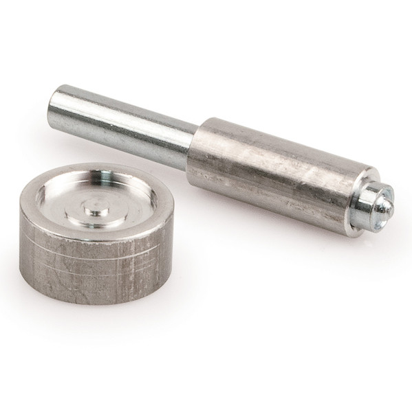
I'm with Glen here except for splitting the post. I've been using the same $5 setter and anvil for years now without any issues.1 point
-
Update time! Made some decent progress over the winter break (despite only taking the actual Christmas and New Years holidays off)! FINALLY finished painting ALL of the pieces in white and clear! The shoulder bridges had a weird paint reaction and had to be sanded down again... then reacted AGAIN in the same spot. Unsure what was going on, but I couldn't leave it like this, so after sanding a third time, I just powered through and decided it was good enough. To mask the helmet, I used one of my sheets of self-adhesive craft foam with a hole cut in the center, then slid the masked-off helmet onto an old cat scratching post on top of a turntable for paint. The second attempt was pretty successful and other than a handful of small dust nibs, the paint and 2K clear went on well - got good coverage and great gloss without any runs or crazy orange peel. I may be able to buff some of the dust out, but it's only visible if you're up close and looking for it. A blast with compressed air probably would have been a good idea. Here's the squint I added, after final paint. And the whole helmet, glossy... Just needs color detail paint and assembly! Now that the shoulder bridges were done (good enough after an extra round of sanding), I went ahead and epoxied them onto the chest plate. Will this hold up? I don't know, but we'll find out! It's super easy to put on and seems to be hold together well, but I may explore adding some velcro just for a positive physical connection at the back of the bridges in addition to the embedded magnets. I didn't really document this process, honestly, because I was pretty frustrated when doing it and was having my fiancé help, so I didn't want to take too much time taking photos, but I did complete the belts after they got final clear. I scuffed up the (perfect lol) surface under each belt box, as well as the back of each box, added some E6000 and then screwed straight into pilot holes I drilled in them in using screws with built-in washers. I made the holes in the belt slightly oversize so I had some adjustment room in case my measurements were slightly off (oops, they were, but I mostly fixed it). I also installed the drop boxes (which have also been backed with self-adhesive craft foam to help keep them from scratching) with 2" black elastic, and just sandwiched them under the large boxes after making holes in the elastic where the screws came through to help hold them. They don't sit perfectly flush, but good enough. Also added some ultra-thin Velcro where the back belt overlaps to hold it to the front belt, and it sits very nice and flush. Speaking of craft foam, I added some to the back of the sniper knee as well, after adding a 3/4" or so block to help shim it out. I'm not sure I'm happy with it still, as it is still tipped too far back and hits the thigh - just not as aggressively as before. I'll probably trim the thighs down and see if it improves before messing with it again though. Aaaaaaand another couple of shots suited up! Obviously not fully-adjusted submission photos, but should give me a good idea of what needs to be noodled with still... The back panel keeps wanting to sag down, but I think once I add electronics behind the chest panel, that will help add some weight and keep the distribution a little more forward. What's left?! - Helmet paint details - Helmet assembly - padding, electronics, lens, frown mesh, tube stripe backing, mic tips (ordered another set from Tony since my last spare pair went on my Hero helmet after the interior paint debacle ) - I have all the bits, just gotta actually install em after paint. - Thermal detonator paint details (I'll do the grey at the same time as the helmet grey) - Thermal detonator assembly - I'll use the same method as the belt boxes, then cover with foam as well - I'll almost certainly need to cut the thighs down, which becomes more evident with each time I actually wear the suit. It may look okay enough for submission, but it's very clunky to move around in currently. I just need to gather as much reference for the shape as I can and maybe draw it out so I can reproduce it symmetrically with a template. We'll see. I don't want to. But I probably will. haha - Final adjustment and photos! Thanks again for stopping by! Hopefully my next post will be over in the Pre-Approval sub1 point
-
Cut and glued on the 20mm outer cover strips. When dry I will do a final fit for the rear. I left some extra to trim about a half inch. Then do the cover strips.1 point
-
Hammer, philips head screwdriver to help split the post, then standard setting tool works for me.
 1 point
 -
Thank you very much! I will be doing a TK build with my brother at some point as well, which is the reason I joined here.1 point
-
Looking GREAT Greg! SO glad to see you removed all the return edge from those tops! You'll be glad you did that... trust me.1 point
-
Then I trimmed the end and sanded some shape to it:1 point
-
Thanks for the pictures! The clamps squad is on its way, securing the knee. I've grinded of the top of my coverstrip allmost entirely, which allows me not only to bring the knee plat close to the shin, thus reducing the gap, it also creates a nice area for glueing. All the clamps definitely help to get wider glueing areas on the sides. Glueing would now be possible I think. The gap on the low end of the sniper knee is about 7 mm wide, shortening it any more will bring the top sides out of allinment with the shin tops. Will this placement be okey? I feel like I shouldn't have cut of all the return edge on the down side of the knee plate. If the plate needs to be repositioned/cut any more I need to know where exactly to do this. If needed, do you think a boiling water treatment could help to further bend the side parts?1 point
-
Hi Jakob, definitely the Sniper knee is a headache , but not imposible to deal with. It's a "Clamps Squad Mission " lokk at the example photos I attached Additional, you can add a small piece of ABS plastic between the Sniper knee and the front cover strip to fill de gap. hope this can give some idea of what todo. cheers1 point