Leaderboard


Popular Content
Showing content with the highest reputation on 07/20/2020 in Posts
-
It's an easy fix, removing the paint and all. That's the only thing that stood out to me about your build, and everything looks great. If you check centurion and eib applications, you'll see the snap unpainted. For example, this request: Great build though! Can't wait to see you approved.2 points
-
Thanks for the advice. I will trim them down to look more like the second image. My personal opinion is, if I cut the trim any shorter than that (although screen accurate) I think it looks unfinished.[emoji16] Sent from my SM-G920F using Tapatalk2 points
-
Impromptu Full Suit Fitting and Assessment Progress on thighs was so good, Andrew H (TK-14023) and I decided to suit up and take some progress pictures to assess how far we are from submission. There is no neck seal in some of these photos, and as we were doing a thigh fitting and trimming, there is no holster attached. Front: Back: Left side, arms down: Left side, arms up: Left side, arms up, close up with rivets, no holster: Right side, arms down: Right side, arms up: Right side, arms up, close up of Han snap: Action pose: 1977 Star Wars card (I always wanted my own Blue Series card): Items for this that remain to be done: Finalize thigh cuts and strapping. Glue outer cover strips on thighs. Submission photos!2 points
-
Never Skip Leg Day Progress-to-date on legs, both thighs and greaves Key resources consulted: AJ's AM ANH Stunt build (https://www.whitearmor.net/forum/topic/40831-ajs-of-am-20-build/) LTM's AM TK ANH Stunt build (LTM's AM TK ANH build) TK-32568 EIB Submission (https://www.whitearmor.net/forum/topic/46507-tk-32568-requesting-anh-stunt-eib-status-am-892/) TK-32568 Centurion Submission (https://www.whitearmor.net/forum/topic/46815-tk-32568-requesting-anh-stunt-centurion-status-am-432/) Crowdsourced suggestions in the AM Armor's Costuming Facebook Group (https://www.facebook.com/groups/840018932822639) Andrew H, TK-14023, who has helped directly with advice and fittings and material components. (Thanks TK-14023, you're the best!) Thighs Front trimming in process: Back trimming in process: Front left thigh, gap filled: Back left thigh, back inner cover strip glued: Front right thigh, ammo belt attached with ridges centered to cover strip: Right side right thigh, ammo belt attached (temporary): Left side right thigh, ammo belt attached (temporary): Back right thigh, inner strip glued and ammo belt attached (temporary): Greaves Left front greave with sniper plate attached: Left side left greave (outside) with sniper plate attached: Right side left greave (inside) with sniper plate attached: Back left greave: Front right greave: Left side right greave (inside): Right side right greave (outside): Back right greave: Greave closure detail: Andrew H and I made so much progress with the thighs that we did some test fittings -- pics in next post!2 points
-
I really liked Tony's bicep strapping bracket system, so I crafted one based on how he detailed his build. I eyeballed his template and made a crude drawing similar to what's in his pics. Smaller for Cameron's build, of course. I have extra ABS cover strip material from various TK builds, so that's what I used as my material for these. Traced mirrored halves onto the ABS. Cut them out. Hacked away at the holes with a Dremel. Mine aren't nearly as pretty as Tony's, but they will do! Stuck some self-adhesive 1/4" neoprene to the backs. Again, Tony's always look so much better than mine!!! I heat shaped them to Cameron's shoulder curves, then followed along with what Tony did to rig the brackets all up. I made a few deviations for Cameron's setup, but it's all pretty much the same kind of result. Top view from the back. Can't wait to hook the bells to this! Speaking of which, I've got shoulder bells and thighs waiting for their straps to cure on them. Gonna try to get the belt finished today.2 points
-
Thanks, will check those links out.1 point
-
Looking really good David. Sent from my iPhone using Tapatalk1 point
-
Even when you think you are done you can find after the first troop or two that areas still need adjustment, event strapping can stretch over time and small adjustments are made from time to time, looking good.1 point
-
I grabbed the part of the sandpaper strip inside and the part outside, then filed back and forth. The strips ripped a lot! But yeah, listen to gmrhodes13 ;-)1 point
-
Every piece adds up in the end, moving along nicely1 point
-
Thanks Rowan. I'll get it done tonight.1 point
-
I only have enough time left today to rough cut the traps, I’ll try and finish them up tomorrow. Right and left. Thanks for the input about the sandpaper DarthBiscuit.1 point
-
Thanks Shawn! I started to use flickr but I'll keep Imgur in mind just in case flickr decides to kick the bucket. You never know with these sites nowadays... So here's the first progress photos. Started on the right bicep as I mentioned before, hopefully I'm going down the right path.1 point
-
It was definitely tricky getting the cutting wheel into the tears, but I was able to get them each started with it. Then I cut some rough sandpaper into thin strips and went back and forth to open it up, until I could fit a file in...1 point
-
Today I’ve cut out the other side and then filed each to be about as rectangley as I can get them. The traps are long enough to where I should be able to use that diamond wheel cutter pictured above, but it’s just barely too long to use on the tears. I might try the other cutter, I’m just afraid I’ll nick the sides way too much. That first bit I used is too large to fit in the trap/tears unfortunately. Depending on how easy the traps are or not, I might go by Home Depot tonight and see if they have any other small bits. Thanks
 1 point
 -
I am using Imgur. It is very easy to use and provides you with a bbb link for the boards. Just copy and paste that link where you want the photo and you are golden! Congrats on your BBB. We received our 2 kits this weekend as well.1 point
-
Welcome, Frank! I'm sorry to hear you'll need to make those adjustments to your ANOVOS armor, but you'll have plenty of support here on FISD, and I'm sure you'll make a fine stormtrooper! Ukswrath has a legendary ANOVOS build thread which you may find helpful, so I've linked it below. https://www.whitearmor.net/forum/topic/35086-ukswraths-anovos-tk-build-stunt By the way, what part of Texas are you from? I consider myself as having grown up in Amarillo, but I also have family in San Antonio and the Dallas area.1 point
-
I’m not on Facebook...did away with it some 2 months ago (and haven’t missed it one bit). If you’d like to post them, please feel free (I’d just ask you to share any pertinent feedback here).1 point
-
Walk around for an hour, try stairs up and down, parade rest, quick movement, and last march for 10 minutes in the neighborhood. You will be looking for pinch points that are not easy to find when just in the armor for 10-20 minutes. I found out the hard way during a long parade troop that my cod returns actually created pinch points halfway into the parade and I still have the scars to remember the pain (no way to stop or anyone to help). Moral of that story, watch the returns. Sometimes it gives the appearance of thick armor, but honestly no one really looks at the individual details (they just see STORMTROOPER! Mom, LOOK! STORMTROOPER!!!) I also have to use the Han hooks to keep the biceps from rotating if I lift my arms to wave or point the blaster up.1 point
-
I realized early on I might need to do some more trimming; velcro and padding are forthcoming with final fitting!1 point
-
Sniper knee plate, you can thin the top part to help reduce catching on the thigh. Look at some pad(s) on the front of the calves to push the sniper plate out (this can also effect how the back closes), so placement will be a compromise. Also do the velcro on the front and back of boots to help with rotation. You will love the ease of putting on the shins with those magnets!1 point
-
To me it looks like you've painted your Han Snap on the ab plate white. If you did, you could easily remove that paint, so you don't get knocked for it. All in all, good job, and good luck.1 point
-
So...an interesting "development" regarding the AM kits. As I mentioned previously, I have an AM2.0 kit that I built into a Sandy: As it's a Sandy, there are a few leftover bits. As I unboxed, unwrapped (Dave does an amazing job in wrapping and protecting all the pieces!...although I abhor the "packing peanuts"), and inventoried the new kit, some of the pulls seemed "off." So I dug out parts from the kit I purchased in 2016 to compare. In this pic, the top row is 2016, bottom row is 2020: Shoulder straps...2020 on the left, 2016 on the right: Belt...2020 top, 2016 bottom: Belt...top view...both 2020 with 2016 on the bottom: This isn't meant to slag off Dave, as I don't believe he actually does the pulls (as I understand it...I could be wrong). This is more of an informational/"isn't that interesting" post. Still, the quality of the ABS is great, there are a lot of extras, including plenty for cover strips. But, I'll be using my left over pieces as needed over the newer versions.1 point
-
It was large on me too. I trimmed the kidney right back so there was not a notch at all. I then had to hot bath the kidney, butt, and ab to fit better. I have it (poorly) documented here someplace: https://www.whitearmor.net/forum/topic/44468-wooks-totally-dirty-td-build-ap/?do=findComment&comment=6143941 point
-
Just let me know if you need other angles etc. Many thanks, Martyn. Sent from my SM-G920F using Tapatalk1 point
-
Thank you. If I get my basic I will be putting in for my EIB asap. I want to be one of the 1000! [emoji16] Sent from my SM-G920F using Tapatalk1 point
-
Looking great, Ken! One of us will be with ya' shortly, sir!1 point
-
Well. I've managed to find time in the doldrums of quarantine. I hope everyone is doing well and remembering to wear a mask. I found it amusing that I put on a mask to start sanding. I've decided to use Angle Gilding's Silvering kit and as such have sanded my helmet back to square one. It, and all the armor, is at 400 grit. I think I'm going to do one more layer of primer, then I can order the chrome. I'm thinking wet sand the finish to 1200 and that should be it. I still have to attach the belt parts, resin greeblies... And I need to sort out my gauntlets. I've heated them up and reshaped them for a better fit on my wrist, but my forearms require a modification of some kind to extend the width of the gauntlets. Bleh. There's a long way to go but its nice to have picked this up again.1 point
-
Thanks for the advise all. Just looked into buying the boots and ImperialBoots.com is shut down until Aug. So I'll see about working on other parts till then.1 point
-
I checked it out and for some reason the words No Award appeared in the box where we normally add a letter to determine how many amours you have helped to build. Occasionally we have some strange IT glitches pop up like the trooping awards for those that never registered a troop but it's all fixed now, hopefully. Carry on with your good work Chris.1 point
-
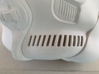
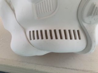
So Today was BBB #1. Although both boxes were shipped on the same day from the same place, one of them was somehow delayed and won't arrive until tomorrow. FedEx came pretty early this morning and I was awoken by a knock on my bedroom door from my son for the unboxing. It didn't take long for me to get out of bed...lol. I decided to get started on the bucket so I could get a few coats of Plasti-Dip on the interior. Please let me know if I need to do any more trimming on the teeth. I masked off the eyes, teeth, and the hovi holes that I drilled and proceeded to coat the inside. I then cut my brow to fit and loosely placed them together so I could get a clearer view of the teeth cutouts with the black background. . I planned on painting the hovi tips but then realized I had purchased gloss black instead of semi-gloss black. The painting will have to wait until tomorrow. I believe I may try painting prior to assembly as the bucket may be easier to maneuver while painting. Any suggestions and tips are appreciated.1 point
-
My apologies, Chris! For some strange reason that accolade is on your profile (still something to strive for, though)! Know that we are here for ya', sir, and I (we) still expect great things from this build! Looking forward to seeing your progress, and as always we are here to help.1 point
-
YOU may have received the “Master Armorer” award...but I sure-as-heck haven’t. I promise nothing other than my best effort.1 point
-
AWESOME news! As a recipient of the "Master Armorer" award, I hope you realize at this point that we expect nothing but perfection, Chris!1 point
-
PM sent. James!1 point
-
Sorry about that, Ken. We had some final tweaking to do. PM sent!1 point
-
Here is the edge line I made to measure for my 25mm cover strip. See how the ridge edge bows out at the bottom so my line doesn’t follow the actual ridge? Is that normal? Or should I measure 12.5mm from the original cut line in?1 point
-
Naptime got messed up today, so I didn't have long to work... I focused on the thighs, so I can re-resin the interiors tomorrow. Sanding went well, then I used one of my trusty files to clean the cover strips. Such great detail in Jim's armor! The seam where he attached the front to the back needed a lot of sanding. I'm sure that's the spot Justin referred to when promoting primer! The repair I made looks great (that off-white spot on the top right)! I had put E6000 in the crack, let it cure, applied resin to the interior and exterior, then laid a square of fiberglass cloth across the inside. It flexes just fine with the rest of the thigh!1 point
-
I think I'm done! Well maybe a clear coat since I have already noticed some premature and not intentional wear from my constant fondling on my newly completed happy thing. Commence photo dump: The wires are snugly concealed under the scope rail. Blast "em!1 point
-
Good progress made today. The belt is done. Biggest challenge of working with a scaled-down suit is that the belt has much more of a pronounced curve. I had to test fit each box to verify that the belt was properly stretched over the ab before making any holes. If the boxes had been installed while the belt was laying flat, the webbed part of the belt would have ended up too short. Below you can see the curve- the belt won't lay flat, but fits nicely on the ab.1 point
-
Proud to announce, that my son is officially a member of the Galactic Academy. Cadet CID 5131 reporting for duty.1 point
-
Thermal detonator fixed with some additional paint. Back to that cod... closer examination of the relationship between the cod and the butt plates (as attached to the ab) showed that the cod was sitting too low, and could stand to be moved up. I noticed this initially when Cameron stood sideways to me. The bottom of the cod and the bottom of the butt plate should be roughly on the same plane, and they definitely were not. I took some measurements, and then took the leap, installing new snaps into the cod to bring it up. The snap placement looks a little wonky, but I can assure you, it will look fine once installed! Okay, so here is the cod installed with the original snaps. Then moved up with the new snaps. Yeah, I guess that I was pretty confident that this would be a better position, just jumping in and installing those new snaps like that! But, hey, it does look better! And in the new position, it emulates the more narrow cod of the TLJ cod shape. Butt plate and cod are in better alignment now as well.1 point
-
Hi all, I'm Paul, I have been a member here for a while, but this is the first time I think I have contributed. Firstly I would like to say that the intention of this build is not to make a hyper realistic E-11 blaster, and I am aware more can be done in terms of detailing than I have done here to make a more accurate representation of an E-11. My goal was to make a reasonably accurate looking ANH E-11 which had the added benefit of an electronic light and sound system. Here is a video of the completed build which I did to talk about the build and demonstrate the electronics. I will start with a list of all the parts I have used and where they can be purchased. Doopy Doos Resin E-11 kit https://www.doopydoos.com/stormtrooper-e-11-complete-anh-e-11-blaster-kit-offer-2685-p.asp BlastFX electronic effects board & Mini Scope Display from TRamp. https://www.facebook.com/trooperamp/ Hegstler Counter box, Trigger assembly, Charging port assembly, & barrel LED mount from Lee McCormack - Shadow Defense Systems on Shapeways. https://www.shapeways.com/shops/shadow-defense-systems Power Cylinders from CSB Props on Shapeways. https://www.shapeways.com/product/ERH6MCTSC/power-cell-assembly-7-with-2-resistors?optionId=59449027&li=marketplace Hollow 1943 M38 scope kit from Bulldog Props. https://www.facebook.com/BulldogPropsJapan/ Various parts from Tino’s E-11 finishing kit including the scope rail and counter bracket. USB charging board. https://www.ebay.co.uk/itm/TP4056-5V-1A-Micro-USB-18650-Lithium-Battery-Charging-Board-Quality-1-2-5-10pc/163005239011?ssPageName=STRK%3AMEBIDX%3AIT&_trksid=p2060353.m2749.l2649 1000mAh Lithium Polymer battery. https://www.ebay.co.uk/itm/Conrad-Energy-Lithium-Polymer-Battery-3-7V-1000mAh-10C-with-BEC-Connector/122527159108?ssPageName=STRK%3AMEBIDX%3AIT&_trksid=p2060353.m2749.l2649 Black PVC tube, clear acrylic tube, & rare earth magnets. All purchased fro eBay. The only glue used throughout the build is Zap-A-Gap CA+ which I purchase from Amazon and Miliput was used as filler which can also be bought from Amazon. Spray paints are from Halfords, Clear coat and detailing paints are all Tamiya acrylics and Revell Aqua color, and the weathering washes are from the Mig range of model making products. My starting point for this build was the scope and mini scope display. I built the scope kit as per the instructions which come with the kit. I then drilled a 3mm hole in the underside of the scope just behind the front leg. The power cables for the mini scope display were then threaded trough this hole and the electronics boards slid into the body of the scope. I then used clear tape to secure the display to the red lens of the display kit, ensuring that the tape extended up the sides of the lens and making sure the display was centred on the lens. This was slid into the rear of the scope where the retaining ring inside the scope then presses against the tape securing everything in place. The clear lens from the kit the goes in on top of this and the scope lens retaining ring is screwed in to secure the whole assembly in place, making sure that the display is oriented correctly to the scope. Next I prepared the parts of the resin blaster kit. The counter box, scope, trigger and power cylinders from the kit were discarded as the would be replaced with alternative parts. The rest had any casting flashing removed, generally cleaned up and washed in soapy water. next I cut a hole in the receiver tube behind were the mag well casting will eventually be fitted. I marked the position of the mag well on the receiver and then marked out an area inside of this which still allowed for the mag well to be glued in place. the corners of the smaller area were then drilled out, and a Dremel with a router bit was used to create the opening. The receiver is actually quite thick as it has a PVC strengthening tube inside of the resin casting. I moved on to the trigger assembly next. A hole was created in the resin trigger group casting by drilling and routing with a Dremel once again. This hole houses the 3D printed trigger assembly, and needs to be snug, but not so tight as to restrict the trigger movement in any way. The trigger assembly was built up incorporating the trigger switch from the BlastFX unit. I opted at this point to cut the wires for the trigger switch in order to feed them through a small hole in the receiver, rather than having to make a larger hole to fit the switch itself through, which may need filling after assembly. I also fitted a small coil spring ( a cut down ball point pen spring) between the back of the trigger itself and the resin trigger group. This spring returns the trigger after it has been depressed. A hole was routed out in the back of the trigger group above the pistol grip where the rumble generator was fitted. Similarly the wires for the rumble generator were cut to accommodate easier wiring later on. Two 3mm holes were drill in the receiver for the 2 sets of wires to pass through, and then the trigger group was glued and screwed into place using Zap-A-Gap and self tapping screws. I chose the method of fixing as I want a very strong bond between the trigger group and receiver. The scope assembly was then fitted to the rail and counter bracket. The holes in the rail and counter bracket needed drilling out to take the screws which come with the scope. I ended up gluing these screws in place as the resin the scope is made from is quite soft, and I did not feel that the screws would hold for any length of time just by screwing them in. This assembly was then attached to the receiver in order to ascertain where the counter bracket would sit in order to place a 6mm hole behind it which would allow wiring access between the counter and the receiver. The scope and bracket were then removed and the front half of the counter was fixed to the bracket with some self tapping screws. A further 6mm hole was drilled through the bracket and counter to give access to the counter. I then cut a piece of 22mm diameter 3mm walled clear acrylic tube to length and slid it into the receiver until it sat where the barrel would normally be. The 3D printed LED end cap was assembled and the unit was then placed through the hole at the mag well, and placed over the end of the acrylic tube. The wires for the LED were once again cut to allow them to be routed back to the counter box. A length of 20mm black PVC tube was cut to fit inside the receiver to cover the charging handle slot so that the wiring in the receiver cannot be seen. This needs cutouts at each end to allow space for the wiring hole behind the counter bracket, and the charging board which sits at the end of the receiver behind the end cap. The Charging board and on/off/charge switch were assembled, and leads soldered on to reach back to the mag well opening. The main BlastFX board, display panel, speaker and selector switch where then all fitted into the 2 halves of the counter box, with the trigger, rumble unit and flash unit wires all fed out through the previously drilled 6mm hole. This hegstler box 3D print is a godsend if you are using the BlastFX system because it has been designed specifically for the components to all fit in. It has a cut out for the screen, a grill and mounting pegs for the speaker, and an assembly which creates the working reset switch, brilliant!!! As it is made for the BlastFX system though, it does have a 'BlastFX' logo where the Hengstler Eagle logo should be, so if that is important for you you may need to find a work around or alternative part. The corresponding ends of the cut leads were fed through the receiver and out of the 6mm hole behind the counter bracket. The cable ends were then rejoined by soldering them and heat shrink was used to cover them. Next the power lead from the main board was fed out of the back of the counter, and along with the power lead from the scope fed through the 6mm hole in the receiver and along to the mag well opening, where they were soldered to the appropriate leads from the battery connector and the charger/on/off switch. At this point the battery was attached and correct function of all the components confirmed, before the charger/switch assembly was glued into the back end of the receiver and all remaining cabling were fitted back into the receiver. I then effectively had a functioning blaster, except that the speaker was not working for some reason at this point. This was resolved shortly afterwards. The rest of the resin detail parts were then added. I also replaced the 2 screws at the muzzle with real metal knurled hex bolts. I also replaced the hex bolt in the end of the pistol grip with a real bolt too. Several other hex screws were used to replace resin cast parts. The end cap was fitted, and a section of foam was added inside. This foam pushes agains the end of the receiver and provides enough tension to hold the end cap securely in place so that it does not rattle around. The mag well and mag were hollowed out to allow the battery to sit inside. The mag well was then glued in place, and rare earth magnets were recessed into both the mag well and mag to keep the two together when the mag was inserted. The blaster was now ready for masking prior to paint. All parts to remain free from paint including the holes in the receiver which the clear tube can be seen through were masked off using masking tape and Blu Tak. The battery was removed. The front end of the scope was also removed to protect the front lens and preserve the metal finish of the screws which hold it in place. The blaster received 2 coats of Halfords grey plastic primer, which was allowed to cure for 24hrs. Then 2 coats of Halfords satin black were applied as a base colour. Once the black paint was touch dry I also added various bits of detail paint in Tamiya XF-16 flat aluminium, and X-31 titan gold. I also touched in any light spots in the black paint with Tamiya X-18 semi gloss black. I used a white wax crayon to highlight the lettering on the back of the scope. I also replaced all the parts I removed for painting, and unmasked enough to check that all the functions still work as they should (and they did this time). Next the blaster was dry brushed with the silver and the scope dry brushed with gold. This is to simulate ware and tear in the paint and finish on the gun. It is done by loading a small amount of paint onto an old paint brush (I find old and worn out ones work the best the more rough looking the better). Then most of the paint is brushed off. I use a folded piece of kitchen towel and just rub the brush on it until almost all the paint is gone, and the brush looks dry, hence dry brushing. Then just brush over the blaster and this will leave what little paint is left on any raised edges, corners and high spots which is generally where ware and tear occurs. Once the dry brushing has had enough time to dry, a wash of Mig ‘dark brown for green vehicles’ enamel wash was applied over the top of the dry brush weathering. This gives the blaster a more dirty look, and blends and softens the dry brushing a bit. When dry, this was then all sealed with a coat of Tamiya TS-80 flat clear. The clear coat seals in the weathering and gives the blaster a uniform finish. The final stages were to remove all the masking, and then hand paint areas inside the vent holes in the receiver which had missed paint due to the masking. I painted these is Revel Aqua Colour 08 black matt. The front of the hengstler box was given a very light brush coat of Tamiya x-18 semi gloss black, and the rear of the box was dry brushed in the same colour to try and give the look of the plastics used in the counters covers. There was then some very light dry brushing of the silver and gold paints again on areas where high levels of ware may occur just to bring out some of the highlights that had been dulled back by the earlier wash. And that completed the build. I would like to say a massive thanks to Paul Whitrow over at TRamp for his advice and encouragement, to Lee McCormack at Shadow Defence Systems for his excellent 3D printed parts which are superbly designed to just work with BlastFX, To Brian at BullDog Props for hid brilliant M38 scope kit and the advice on getting the right one for my needs, and to Tino for his fantastic detailing parts kit and scope rail. You all made this build a lot easier to pull off Guys thank you. Thanks for taking the time to read through this long post, I hope you enjoyed it. Paul1 point