Leaderboard


Popular Content
Showing content with the highest reputation on 11/06/2020 in Posts
-
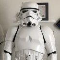
Hello all. Yesterday the BBB came. Pics are here, and I have of course suited up to see how things fit. I do have some questions. I will start with the unboxing. Fedex came promptly 2 hrs and 15 mins later than predicted. You can imagine my anxiousness for that time, wondering where the truck was being robbed. A few posed pictures and I immediately went into opening it. And the money shot is here.. What a manchild. lol!!4 points
-
OP (MV) Post #34: Kittell Belt & Supplies Not Previously Documented Not any actual progress here, but I just wanted to further document several build supplies which I had not previously photographed and posted in the past several months. I've probably said this a million times, but my hope is that this thread can be a resource to future builders. Thus I've tried to thoroughly document every aspect of the build, whether it be images of raw armor, visuals of every cut into the shiny plastic, or purchase links to the tools I use. In that vein, here are some additional acquisition notes: TK canvas belt from Rob Kittell (Imperial Issue). This appears to be of excellent quality, and came highly recommended by many troopers of FISD. As stated on the Imperial Issue webpage, when sizing always take your waist measurement with your ab and kidney armor on, and do not add in any breathing room to your number. Rob already takes that into account. I generally wear a US size 34 pants, and my armor-on measurement was just shy of 41 inches (104cm). Also, Rob's logo and slogan are awesome! Humbrol French Blue #14 enamel paint. As discussed in a previous post, I initially had a hard time sourcing the French Blue enamel, and couldn't even decide if I wanted to use that or the Mediterranean Blue, but I finally broke down and got the FB from Trooperbay on eBay. Testors Semi-Gloss Black enamel paint (Hobby Lobby). For the longest time I was unable to find this in-stock at my local Hobby Lobby or Michael's stores, especially since all the bottles were always mixed up and never in their correct bays, but I eventually got lucky. I had initially planned on painting my vocoder and mix tips with a matte black, to add contrast to all the other shininess, but it turns out that's really actually an ROTJ style. Superfine White Milliput (Hobby Lobby). This may not seem like a standard ABS TK build item, but my plan has been to use it on the inside of the helmet to reinforce the mix tip wells. The ABS is super thin there, due to the extreme stretching in that area during the pulling process, and I didn't want to rely solely on a larger washer. I've also considered using it on the interior of the ears (either that or a piece of ABS) to reinforce where the countersunk screws will be drilled. Purchase tip: Never shop at Hobby Lobby without a minimum 40% off coupon. White adhesive velcro (Walmart). I found this in my office supplies/mounting box and figured I would use the soft (loop) half on the back of the thermal detonator clips to keep them from scuffing up the torso armor behind the belt. Industrial strength is unnecessary; the cheapest option with an adequate adhesive will do. Rust-Oleum Black Truck Bed Coating Spray (Amazon). Chalk this one up to @TheRascalKing, who swears by it. This is intended for the interior of the helmet, and unlike plasti-dip, apparently it can accommodate adhesives for velco padding, fans, etc. It will be a nice way to black-out the interior and avoid the peeling that plasti-dip is also susceptible to. Plus the texture looks awesome (on the builds I've seen). And that's all for now. If any builders want a complete index of my tools, supplies, and parts, I have documented them on my Table of Contents on Page 1 of this thread, and they are even better-presented, with purchase links, at the beginning of my PDF compilation of this thread. MV Printable/downloadable PDF of my entire build thread to this point contained in [THIS SHARED FOLDER]. The PDF will be updated within a few hours of my own new posts and will note sequential version numbers and revision dates.2 points
-
Hi Josh and welcome to the FISD. Is the blaster meant for trooping or display only? (asking because of the weight, less weight is better for long trooping days) Beside Praetorian there are other sources for rubber blasters, but these always turn out heavier than other kits. Resin is better and 3D-printed kits are the light-weightiest on the market but require serious sanding.2 points
-
As you can see in the references of the original suit, the sides of the shoulder weren't cut perfectly straight. They were actually curved cuts, and this helps them fit closer to the chest and back in later assembly. Since you cut so close to the edge, you can always add the slight curve to the sides. Good work2 points
-
Correct on the ‘tweaking’ , there is a bit more work to be done and Dave is taking care of me. Understand the difficulties with commission builds , can’t be easy at all going off pictures and measurements, so my hat is off to him . Wish I had the time to do this myself but since COVID hit I have had zero time to take on a project like this . We’ll get this [emoji106] Sent from my iPhone using Tapatalk2 points
-
Well good news , I was able to get ahold of DDD and after reviewing some of pictures there are some 'tweaks' that need to be made to the arms and legs. I cant speak highly enough of DDD and the customer service he provides with his products , it's a rare thing to find someone like Dave that takes pride in his work and stands by his product. Big shout out to Daves Darkside and the work he does. Will post a few more pics when things get trimmed up.2 points
-
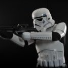
Nice work trooper, a few things you may want to adjust before the DO's get here: Forearms are at different heights to gloves, one almost hitting handplate, the other has a large gap If you haven't you may want to place some foam behind the sniper plate so it doesn't interfere with your thigh TD spacing appears a little off, small gap between caps and panel, also your clips are very long. Ideally screws should be a little smaller. You could trim a little more of the top and bottom of your belt as there is a lot of extra material there A few other images the DO's like to see. Close up of the side ab/kidney rivets Close up of the sniper plate, front and both sides. Close up of bottom ear screws Good luck with approval2 points
-
hey all, so ive been tryin to find a good blaster, i message praetorian and got no response, the only person ive been able to actually get to respond was the field marshall E-11 kits, and while these are beautiful, im looking for something a bit more budget friendly. ANH is the style im looking for any help is appreciated!1 point
-
Name: Colin Adams TKID: TK-25622 Forum Name: OddViking327 Garrison: Golden Gate Garrison Height: 72.5” Weight: 198 lbs Armor Maker: AM 4.5 - Dave’s Darkside Depot Helmet Maker: AM 4.5 - Dave’s Darkside Depot Blaster Type: Imperial Arms 3D - E-11 V3 (with modifications and improvements) Boots Maker: Imperial Boots Canvas Belt: Rob Kittell Hand Plates Type: Flexible Silicone by Just Joseph Electronics: Speakers and SHA by Ukswrath, fans by me Neck Seal Type: Imperial Boots Holster Maker: Darman’s Props Armor Build Thread: https://www.whitearmor.net/forum/topic/49991-oddvikings-anh-stunt-build-am-45/ Blaster Build Thread: https://www.whitearmor.net/forum/topic/50223-imperial-arms-3d-e-11-version-3-kit/ Photos - Body: Details: Interior: Blaster: Helmet:1 point
-
I agree. I would expect them to provide you with the materials needed for the adjustment, if they haven't included any already, and possibly something else to make the trouble worthwhile. They have a great reputation, so I don't doubt they will work to make it right.1 point
-
That’s a great point. I know “adding plastic” is nearly impossible vs removing some.” You know the thought did occur to me to just gain weight. My GF quickly shut that down. I am wanting to see what RSP is going to do about the 3” mistake. After all. What if I incorrectly paid them by 13%? They would want their money. Sent from my iPhone using Tapatalk1 point
-
I can understand your nervousness, we all faced it. Fortunately, there are plenty of resources here to guide you along and once you make that first cut, you'll feel more confident. Despite the frustration, none of what you are experiencing is unexpected. Just be glad they are too big rather than the opposite.1 point
-
Thanks guys. I did contact RSP about the 3” Miss on the dimensions I sent them. I’m awaiting a reply. 1” I can understand. But a 13% Miss in the dimension is excessive. Especially for the cost. And now I’m VERY nervous about cutting this armor. Sent from my iPhone using Tapatalk1 point
-
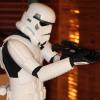
Congrats on your BBB day! Did you attack the Fedex driver? Haha. As Shawn already mentioned, you will definitely want to trim down those thighs a bit. Bra-hood calf closures can apparently have a tendency to open up, so perhaps some more seasoned Troopers can provide you with insight on how to minimize that. Personally, I try Cricket's magnetic shin closures. Relating to the drop boxes, I think you'll actually find that that "lack" of quality is actually screen accuracy. The belts commonly had fraying, and the drop box elastic was often trimmed around the snap. I believe Cableguy has some photos of his replication of this on his fb page. Below is a screen reference, through from ANH, from the FISD Gallery.1 point
-
Or, peel the cover strip off now, and hot water bath it to shape … then re-E6000 it to the calf.1 point
-
Congrats on your BBB!!!!!! It definitely appears you have a little work ahead of you. It almost looks like you have enough room to completely cut out on either side of the cover strips on the thighs, trim to fit, and reattach new cover strips. By all means, this is only an observation and I wouldn't go in gung ho based on this, but it should be an easy fix nonetheless. You will likely have to remove the cover strips on the shins, trim to fit, and reapply the strips. You are 95% there!1 point
-
Here’s a pic to show it more clearly. Original to the left. You can also see on the picture Glen provided (same bell) that there is indeed some return left at the bottom. So I did what you did and left some, it’s the most accurate but, perhaps trim a tad more of the ”centerpart”, you can compare to the original.1 point
-
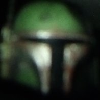
ok, so now I have some questions: Everything seems to fit well, except the thigh pieces. I am considering three options. 1. do nothing its normal, and please tell me if I am over doing it, 2. I raise up the thigh plates by shortening the elastic holders of the thigh plates to the underbelt, or 3. I need to cut and resize the thigh plates. There is a distinctive gap in the top of the thighs. The knees are normal-ish, but my girlfriend can put a full hand inside at the top as it was fit on the first time. three fingers if she does sideways. Second to the thighs, the shins are super hard to hook up and tend to pop apart. I can slip my foot through them without unhooking them. This also seems too loose. Please advise on this. you can see from my left shin plate, its popped back open but again I can slip it on closed. Next, I noticed the bicep plates are not linked or tied to the shoulders in any way, and they kept sliding down to my elbow. Which makes me stand a little funny, unless im doing some sort of action. I am thinking I need to connect the biceps to the shoulders to keep them in place. For ESB, is this something I can do, or what is the preferred suggestions to make this fit a little better? Another "fit" concern is the belt and drop boxes. The snaps are nearly centered on the lower abdomen plate, however, and maybe its just poor quality, but the drop boxes are right there, and cut.. leaving well, less than desired appearance. The craftsmanship is not what I would've expected. Lastly, I noticed the green film inside the helmet is rather flimsy and cheap and again, poorly crafted. Is this normal? All these little detail points, I will admit, once fully on, it doesn't look half bad. I think this picture is the worst ever. You can easily se how the thighs are too big, and even at the calf.1 point
-
Congratulations at long last, you must be very pleased, and you look great. Well done Rebecca!1 point
-
Calf cover strips are done. However it looks like the cover strip straightened out the outer side of the left calf and it is under some tension to close. I will need to give it another hot water bath to get a better curve to ease any stress on the magnets. I am giving the glue ample time to cure to avoid any issues.1 point
-
Lol!!! For sure Sent from my iPhone using Tapatalk1 point
-
Welcome to the TRUE home of white armor, Garrett! Lots to learn here, but know that we are here for you every step of the way on your journey to becoming a shiny-white spaceman! Although most of your questions can be answered by going through our forums, always (and I mean ALWAYS) feel free to ask any questions you may have. We are here for ya', future trooper!1 point
-
Welcome Garrett!1 point
-
A couple of references1 point
-
them porch pirates1 point
-
"Stalks every vehicle coming down the street"1 point
-
Applied the paste to the parts... lets see how this goes. back of thighs: Kidney shims: - may have applied a bit thick here... but well see1 point
-
Started last weekend. Hyperdrive activated!!!1 point
-
Daniel Jimenez TK 26306 Letter size Justjoseph63 Thank you!!! http://www.whitearmor.net/eib/certificates/26306-eib.png1 point
-
Thank you! The feedback I have gotten in this process has helped make the armor even better. This is a great community!1 point
-
Congrats! Excellent work and perseverance through all the challenges, particularly of 2020! You have overcome! Sent via Imperial Tapatalk Comms1 point
-
Congrats!!!! Sent from my iPhone using Tapatalk1 point
-
Great news, congratulations trooper1 point
-
Congratulations Captain!!!1 point
-
Congratulations1 point
-
Thanks @gmrhodes13 for some things to look out for. I am not sure about why the hand/forearm gaps were different, just how they were tucked in at that moment (no mirror as I put on the gloves before the shoot). They usually are fine, but the rubber cuffs sometimes hold the forearm up a little I guess. Here is just a few shots later doing action poses, and they are back in line: The Thermal Detonator will be trickier. I am guessing the end caps are maybe too wide, which might fix that spacing? The screws and clips came with the AM kit, but I can swap the screws and trim the aluminum down. Let me know if the end caps are what need fixing. Here are some of those other pics you said might be needed:1 point
-
OP (MV) Post #32: Thermal Detonator Part 2 In my previous post (Part 1) I began my thermal detonator, and in this post I will continue with painting the tube and installing the control panel and end caps. But first, a little twist to start us off. As I began to look ahead towards altering my universal-sized clips to fit my 2-inch (50.8mm inner diameter) tube I felt the need to study screen-captures of all the TDs in ANH. Essentially I wanted to get a good sense of TD height placement relative to the belt, as well as gauge the angle at which the control panel points. While the FISD Gallery has excellent content, for my purposes the 1,059 screen images captured chronologically by Jeklynhyde in this post provided the easiest access. I sifted through that image bank, along with Gallery albums from @Darth Aloha and @Locitus and all 119 pages (21,248 images in case you're wondering) of 4K ANH caps from starwarsscreencaps (hereafter referred to as SWSC) and saved 129 images to this google drive folder (yeah, I went a bit Han-boring-conversation-anyway heavy) to compile into a RogueTrooper-frown-like thermal detonator collages shown at the top of this post. Though my initial intention had been to capture detonator-belt height alignment, I also included images which documented other details of TDs, such as mounting clips and screw placement. The photos shown at the top of this post are actually downsized versions semi-optimized for viewing at 1,000 x 750px on the FISD web-platform, but if you click on the images they should link to the full 2,000 x 1,500px versions which contain un-scaled captures from the 1,920 x 1,080 (really 1,920 x 817 at the 2.35:1 anamorphic screen ratio) source imagery from @Jeklynhyde. The un-scaled snips from SWSC are from their 3,840 x 1,600 native resolution. Jeklyn was also kind enough to provide me with additional screen grabs upon request, on multiple occasions! Of the 129 images kept, 27 came from SWSC and 18 came from the FISD Gallery; none of the Gallery images were used in my final compilations. I used a transparent background on the images so that they would display cleanly in Tapatalk and in the current and future color schemes of the whitearmor site, and every individual image snippet is ordered chronologically by appearance in the film horizontally across the two master compilation images. The eight images below are quarter slices of the two master comp images, should any of you want to view the full-resolution content in-line/thread. HERE IS A LINK to my google drive folder which contains all eight of the above quadrant photos, as well as the master compilations. Contained in the master folder of copies of the versions of the images with three background colors—transparent, FISD gray, and white. While sifting through the 22,000+ ANH captures I tagged some for future projects, such as compilations of other parts of ANH TKs. The sniper plate, knee ammo belt, shoulder bridges, drop box alignment, and mobility cuts immediately come to mind. I've already developed a magnifying bubble overlay system that I'm going to use, and perhaps the images might be a helpful addition to some of the "Specific Parts" sections of the Gallery. In case anybody is interested, below is a Google drive folder which contains every SWSC capture I retained from the original image bank. These 3,688 images include every instance in which even part of a TK (and TD Sandie) are visible, whether it be part of a helmet peeking out from behind another character, a knee-pack barely above the trash compactor water, or Luke wearing TK-421's belt. Those with an extremely keen eye might notice some sequenced images missing, and that's because 45 images in the SWSC bank were repeat frames (which I excluded), likely due to capture, upload, or database errors. EVERY ANH TK from SWSC (3,688 images) Staring at all those images for hours (days) is now making me want to get a UK/metric-sized TD, but for now I'll have to make due without (anybody have a spare?). Seems I'm getting caught up in the finer details like our good friend @CableGuy. Lest any readers get bogged down in the next three sections (Painting, Re-Squaring, ABS Installation) of this post, I'd like to draw particular attention to the last section at the end, related to modifying my belt clips. I have diagrammed a couple options and would LOVE some feedback. Painting In continuing with Tony's documented paint process, I taped up my tube in order to cover a space the size of the control panel. To perfectly center the panel, I took the total length of my tube (7.25 inches or 184.15mm) and subtracted the width of my control panel (122mm), which left me with roughly 62mm. Since this represented the total remainder width, I divided it by two, and thus my guide marks were made 31mm from each end. Keep in mind that, if you're following my posts as a guide, your measurements will vary based on the figures you cut your tube and panel to. I then used my actual finished panel as a straightedge to guide my ballpoint PEN as I traced the border. I emphasize using a PEN because, even though I know pencil wipes off ABS, I wanted to avoid marking the edges of my control panel. This would have likely happened with pencil lead, but did not occur with my ballpoint pen. Do not worry about getting a perfectly straight line since the actual cut line will be inside of this original rough border. Once I finished the outer border I measured 1/8-inch (per Tony's recommendation) inside of it and drew an inner rectangle, again using my panel as a straightedge. This interior line will serve as my cut line guide for trimming off the excess tape. To guide my Xacto knife I used leftover pieces from my end cap trimming, despite the fact that achieving a straight line is not necessary for this step. I'm a bit of a perfectionist; perhaps @justjoseph63 understands. Haha. The rationale behind cutting the shape of the blue tape down to a size smaller than the actual control panel is to ensure proper spray paint coverage, which will just barely (1/8-inch on all side) overlap with the panel. Not having this overlap could result in a sliver of unpainted pipe showing next to one or two of the edges of the panel. Once I had my control panel tape cut and the excess peeled off I masked off the edges of the tube which would be covered by the end caps. I wanted to leave 1cm of unpainted pipe on each end in case I later decide to glue to caps on, since the glue would best adhere to the sanded pipe rather than a painted surface. I used my handy pencil-in-clamp technique to mark an unnecessarily-straight line, knowing that there would once again be overlap with my painted surface and the end caps. Recall that I tapered the ends (with sandpaper; see photo towards end of that post) of my tube and I wanted to ensure the painted surface extended into the tapered area to combat possible paint-scraping when finally sliding on the end caps. With acceptable weather conditions (51% humidity, 70s f indoor temp) I set up in my garage and sprayed two coats of Model Master Custom Spray Enamel 1923 Gunship Gray FS 36118 with some drying time in between. I might have gone a bit thick, and got some orange peel, but only if you look really closely and with certain light. Nobody at a troop would be able to notice it. I let it dry for several hours then removed the tape on the panel area and ends, and set it aside to further cure overnight. EDIT: Later in my build I discovered that Model Master 1923 Gunship Gray is too dark for the Thermal Detonator, and more appropriate sprays are Testors 1237 Semi-Gloss Primer or Testors 1238 Gloss Gray. Here are some photos of the completed paint job, including photos which shows the amount of overlap that the panel and end caps will have once positioned properly for my 7.5 inch (190.5mm) wide TD. Control Panel Re-Squaring While test fitting my control panel onto the tube I discovered that somehow my panel was no longer perfectly squared, which means my previous sanding guides must have been off. The image below shows the arc length difference between the two ends of the panel, indicated by the two pencil marks a few mm apart at the bottom. The photo depicts the short end of the panel, while the other longer side extended to that outer pencil mark. Thus I proceeded to mark off the sliver on each side which needed to be sanded. To do so I evenly split the length difference I needed to make up so the result would be a very small amount coming off on both ends of the arc. It took several attempts, but I finally managed to lay down the tape in straight lines, checked by looking down the tape line in a fashion similar to taking aim with an E-11 Rebel blaster. The tape would obviously serve as a visual guide while sanding but I decided to add a second layer of tape in hopes that it might create a bit of a barrier to keep me from over-sanding. It's always a good idea to use proper PPE (shown above) when sanding ABS, as even sanding small amounts at a time can add up over the course of a build. Save your lungs (and eyes and fingers) people! I was happy with my final results after measuring the arc lengths again on my spare PVC pipe, so ONWARD! Control Panel & End Cap Installation With the spray paint having had a couple days (excessive) to fully cure I set out to install the control panel and end caps on my tube. However, I first wanted to drill a couple air relief holes into my tube in the same fashion that AJ Hamler did on his build. These holes would theoretically make it easier to install the snug-fit end caps, but since the plan was to install the control panel first, it's unclear if the holes would end up being sealed off anyway. I guess that depends on how tight I get the panel adhered down onto the tube. I marked dots where I wanted to two holes to be drilled, which would be situated beneath the raised areas of the control panel (buttons and round washer style detail). I first drilled pilot holes with a 5/64 bit then graduated up to and ended with a 3/16 bit. It was my first time drilling into PVC and I was surprised to find that drilling the holes did not result in PVC dust, but instead several curly-Q shards of plastic. Fine by me, as it made cleanup a breeze. After-the-fact-tip: Once again I over-engineered another aspect—the relief hole cutout—though I only realized it after the next step of gluing the panel down. Another perfectly suitable location, and less likely to fail due to glue sealing, is to drill the relief hole beneath where the TD clips will be seated. So basically the hole would be covered by the clip. Alternately, if you plan on using clip screws rather than bolts with nuts, you could actually use a clip screw hole itself for air relief and attach both end caps before driving in the final clip screw. I measured and remarked the previously-determined 31mm (from tube ends) guidelines with blue tape to ensure proper centering of the control panel, and also added a few pieces of tape on the top and bottom long edges of the panel to help align it vertically. I then sanded the underside of the panel with 120 grit sandpaper, but kept away from the tips of the edges so as not to create any rough ridges which might later be visible (via magnifying glass, haha). And then came my first time use of the glorified E-6000, and my amateurism showed. My goal had been to keep the glue away from the panel edges to avoid any seepage out from beneath the panel, because though I knew that E6000 can simply be rubbed/picked off of plain ABS, but I wasn't sure how it would react to the paint and didn't want to risk peeling some of it off. I attempted to create some gaps in my glue lines in order to maintain the functionality of the air relief holes, but who knows if it will have all filled in once the glue is compressed. Below are some photos of my E6000 application, and it quickly became apparent that I used far too much, as it seeped out on the sides. Tip: As seen in the second photo, I used a metal ruler pressed against the edge of my TD tube to ensure that I had the control panel level, and then I taped it down to keep it from sliding around. You want to make sure to position it perfectly parallel and perpendicular relative to the form of the tube, since you don't want your panel to be twisted on the tube and look crooked. In another first, I finally put my magnet sachets (creation thread) to use in conjunction with a couple clamps, as shown above. I then set the TD aside for the E-6000 to cure for several days, and proceeded to work out my TD clips, described in the last section of this post. Several things I learned during the E6000 application process: E6000 is as slippery as they say. Combat this by having adequate guidelines/marks so proper alignment can be maintained. Also use tape to keep pieces stationary in their intended locations before applying clamps and magnets. E6000 will react to at least some paints. This is perhaps what worried me the most while I waited for the glue to cure. The seeping glue immediately absorbed the color of the spray paint so I was left with what appeared like a wet paint mess. NEVER BE IN A HURRY. I repeat, NEVER. In an effort to get the control panel installed prior to heading into work, I did not allow myself enough time and I rushed through the glue application. The eye test should have informed me that I used too much glue based on the applied volume and available surface area. Consider your build a marathon, not a sprint. And actually—just completely forego the competition metaphor altogether. This is a work of art, and art takes time. With curing complete it was time to remove the clamps, magnets, and tape, and hopefully clean off the excess E6000. The moment of truth. Would everything be ok with only minimal paint imperfections, or would the paint peel and require me to start over... Looks ok so far... but... Sure enough, my paint job was affected, though at least it didn't peel off, perhaps due to the two-coat application. Honestly it's probably Legion-passable, but it's definitely not Caleb-passable. I'm not yet sure what I'll do, but I see two options: Order new ABS parts and hone my TD assembly skills. Use extra PVC but purchase more spray paint. Yes, I previously over-sprayed. Sand down the blemished parts, mask off the ABS parts and re-spray over the problem areas. I'm leaning towards option #1, especially since it'd be nice to keep my blemished TD as a memento, but I'll need to decide whether to spend the $30-40 from my nonexistent budget. Since this is my first completed armor component of my build, and despite my errors, I've been excited to finally see a real-life (sorta) TD on my desk! Moving along. Though the photos above show the TD with end caps installed, at this point in the process, with the blemished paint dried, the next thing I did was measure the exact distance each end cap would need to be pressed onto the tube to achieve the 7.5-inch (190.5mm) wide detonator. Since I had cut my PVC tube to 7.25 inches (184.15mm) I knew that each cap had to extend 1/8-inch (3.175mm) beyond the end of the tube. With 20mm end caps, simple math left me with 16.825mm of tubing needing to be covered by the caps on each end. I measured and placed blue tape just beyond that amount on both ends, which would serve as end-stops for my caps. My plan had been to proceed with Tony's hot water bath technique, boiling the caps for 30 seconds each and then sliding the caps onto the tube, but I decided to skip that step with my already-blemished TD. When going the cap-bathing route, always remember to wear appropriate PPE. Below I have my imperfect but nearly-completed thermal detonator with clips mock-mounted. Clips Modification Options This is where the real fun begins, and where I am seeking additional guidance from seasoned veterans. As mentioned in Part 1 of my TD build, Tony's TD clips require a slight modification in order to get them to properly cradle my 2-inch (50.8mm ID) pipe. @ukswrath constructs his clips with universal sizing in order to fit both 2-inch and 68mm (screen-accurate OD) pipe, and below is the process he sent me to adjust them to fit my TD. Completely assemble the TD as normal. Install the clip and screw closest to the control panel. Putting pressure on the clip and screw (not to rip out the screw) form the remainder of the clip around the tube (the material is pliable). Afterwards mark, drill and install the second screw. Reshape the belt clip portion as/if needed. That seems simple enough, but a thought occurred to me upon assessing the procedure. There are actually two routes I could take while tightening the wrap-around of the clips which would result in two different final forms. Below are some diagrams I created to provide a visual reference for the two routes I will need to choose from. In the first photo below, Tony's clips are shown in their current unaltered state with the two versions (2-inch and 68mm) of pipe overlaid. The second photo shows the unaltered clips with 68mm pipe and two orientation options with altered clips and 2-inch pipe (moving/transitioning gif). Option #1 has an elevated tube and Option #2 features a lower position. For simplicity's sake, following the images are notes on the differences between the two options. Note: The images above were designed at 100% scale (printable), though the clips were thickened for clarity. The profile of the 68mm clip was a trace of one I received from Tony, and the profile of the control panel was rough traced and scaled from photos of my ATA panel. Option #1: Raised Increased/lengthened clip wrap-around. Essentially a more enclosed cradle. Clip end closest to control panel sits higher (y-axis) on the tube, and is therefore more visible. Control panel points steeper/higher vertically. The top of the 2-inch TD sits level with top the 68mm on the y-axis (vertical position relative to the belt) Option #2: Lowered Standard ratio amount of clip wrap-around/cradle. Clip end is positioned as intended on the tube's y-axis Control panel points at the appropriate outward/upward angle The bottom of the 2-inch TD sits lower vertically on the y-axis relative to the belt, barely below the typical bottom of the 68mm tube. The vertical portion of the clips between the tube and the belt will be a bit more visible than usual. Personally, I'm more attracted to Option #2 (lowed) since I believe the slight drop in the position of the TD relative to the belt will be mostly unnoticeable, or at least less so than additional surface area on the TD being wrapped by the clips and the control panel facing more upwards. That, plus it seems that many troopers seem to set their TDs too high on their belts anyway, perhaps to match some film anomalies, or simply due to dressing challenges. Then again, if TDs were ever not in level alignment with belts in ANH, they were always elevated rather than lowered, so what to do, what to do. I suppose there might be an Option #3 of splitting the difference between the first two, or perhaps even trimming the end off from where the screw hole is. But I'm not sure I have the tools for that plus the new mounting holes I'd have to drill would be too close to the other holes. SIDE NOTE [beware of math ahead]: Regarding trimming the clips relative to the reduced circumference of smaller pipe. The outer diameter of 2-inch (ID) pipe is about 60.3mm, which equates to a pipe circumference of 189.44mm. The circumference of 68mm (OD) pipe is 213.63mm, so the reduction of 24.19mm down to the smaller pipe represents an 11.32% decrease. Based on eyeballing (I don't have proper clips AND pipe to measure) it appears that clips are intended to cradle/surround roughly 40% of the TD pipe, so on the 68mm pipe that would be an arc length of roughly 85.45mm. For a consistent pipe-to-clip ratio while maintaining the standard height and angle of the control panel, I would therefore want to reduce the 85.45mm clip length by the previously-calculated 11.32%, or 9.67mm. Trimming the nearly 1cm off would bring the new end in barely past the current pre-drilled holes as expected, requiring new ones to be added. So Troopers, what say you? [Since I'm shameless / "this is my most desperate hour", in addition to the Troopers already mentioned throughout this post, I'm also tagging @TKSpartan, @Sly11, and @gmrhodes13 to harness their expertise.] Apparently this two-part thermal detonator series has now stretched into a proper trilogy. Seems appropriate. I will proceed with Part 3 based on the feedback I receive. Thanks in advance! For reference, below are two photos of my clips which I had included in an earlier post, as well as information for confirmed TD pipe sizes for various armor makers. @TheRascalKing was kind enough (as always) to measure and photograph his ANOVOS TD for me, and other than RS (which we can safety assume is 68mm), I heard back directly from all the makers. ATA: 2-inch not included (USA) AP: 2-inch included (Canada) RS: 68mm included (UK) RWA: 68mm pipe included (UK) T/MC / FAC: 68-69mm metal pipe included (USA) WTF: 2-inch included (USA) RT-Mod: 2-inch included (Canada) AM / DDD: 66-67mm (est.) plastic pipe included (USA) CfO: 68mm included (UK) TM: 68mm included (UK) MTK / TB: 2-inch included (USA) ANOVOS: 67mm included (USA) Printable/downloadable PDF of my entire build thread to this point will be updated within a few hours of my own new posts and will note sequential version numbers and revision dates. NOW AVAILABLE HERE NOTE: Some of this post's content is displaying incorrectly in Tapatalk, with entire paragraphs of text emboldened and miscolored, and at least one entire sentence of text missing. Images have been, as they always are, optimized for web viewing on FISD.1 point
-
I would suggest moving to the build sections, you will get a lot more feedback there, ANH is here https://www.whitearmor.net/forum/forum/80-anh-build-threads/1 point
-
Hello all, Gmrhodes: Thank you for the build threats. I have allready devoured them some days ago. And when the helmet arrives I will read them again...and again and again :). I also watched some of cableguys videos. TkSpartan: Thank you for your encouraging words. I am a little bit scared about the worke :). But I think this is the right place do get the job done. When the helmet arrive I will send a picture very fast ! I promise Sly: I will do so :). Thank you. Hi Dan ( CableGuy ), a special THANK YOU to you;). I will Start this project because of your threats. Some weeks ago I started to looking around. Like the last years I was at the RS propmaster side and was dreaming. At this Moment I was at my 20 year dream mode ( only for looking around) .... But than there was it. A HDPE helmet.... And I thought. Oh wait....the original helmets were not out of ABS? that is interestig. So I looking around and found this Website ( white amor) . I read a lot... So the HDPE helmet piqued my interest. The Website kindled the fire even more. But then I was about to give up. I was so interested in the HDPE helmet.. but I thought it is a little bit crazy to spend so much money for the RS Helmet..... But then I found your threats about the HDPE Helmet .... and this helmet looks amazing ( paintjob ). And it is a little cheaper. Than I read all your posts.... And after that I decided that I will start this project! Some minutes later I ordered a kit from DA props. One question. If I get started. Should I stay at the replica Forum....or should I go to another forum for posting my progress? ( Not only for the helmet. Also for a armor). Have a nice day ( all of you )1 point
-
the front is secured by a split rivet, and has one small snap with the cap type head, or female the rear has 2 male snaps. they are not 5/8" heavy duty, but are instead the smaller jeans style snap.1 point