Leaderboard


Popular Content
Showing content with the highest reputation on 03/21/2020 in all areas
-
Wow I’m overwhelmed thank you all so much. I will try my best to improve my suit to reach Centurion. A big thank you to Sly for putting up with my multitude of questions. Thanks again for all your time, I’m truly grateful. Sent from my iPhone using Tapatalk3 points
-
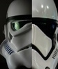
Oh right! The Sugru putty! Definitely looks easier to use! lol Thanks for bringing it up! Imma put it on the list. In the future I will consider getting electronics, though they are a bit pricey at the moment so I'll hold off until I can get my kit approved for Centurion status first and still need to get my DLT-19 Heavy blaster. Also I did like how CableGuy did his helmet on the inside. I'll use it as a reference:2 points
-
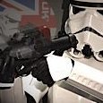
Thanks Brave! Hope to see your build soon as well! Lol only thing I forgot to get is the gloss white paint and earth magnets to hold the Face and the Cap in place and for positioning. Also forgot that I need a mesh for the frown. Also need to consider how I am going to position the lenses when the time comes. Yeah that was my bad lol. I forgot to mention what the armor kit was. I'll do my best to not miss the detail when I am posting stuff from now on lol. But I believe your videos is something I will watch for reference. Thanks a bunch!2 points
-
Oh I did also get lights going in the dome.2 points
-
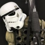
Hello there! I wanted to get started with forging my ANH armor kit that is the stunt build. The armor kit, btw, is an ATA kit. A bit nervous about this, but excited at the same time. I will start by forging the Helmet first. Below is the set of tools I use. Which includes the following: Heavy Duty Razor Knife - Scissors - A Rotary Kit w/ Dremel Drum attachment 120 grit - Screws and white Hovi Mic Tips that came with the armor kit out of the box. Also got the paint and brushes I needed to touch up on the stripes, frown, and the vocoder. Though I did forget to get the gloss white paint for the screws that holds the ear plates. I'll be sure to get those soon. Humbrol # 85 , Humbrol # 5, Humbrol # 14 , and Humbrol #48 I am a bit hesitant at the part where I need to trim the edges of the helmet though. I took a look at TK1636's video on some guidance on how to trim it: Though my gut instinct tells me, based on the helmet I have, I should cut the excess plastic on the top of the face and underneath the face, while leaving the side untrimmed so I have enough plastic for the ear plates to be screwed in? What are your guys' and gals' thoughts on how I should proceed with the trimming? Thank you for what ever guidance anyone can provide.1 point
-
Name: Jonas Andersson Future garrison: Nordic Garrison Armor maker: SDS (Modded) Helmet maker: SDS (Modded) Cloth belt maker: Imperial Issue Neck seal maker: SDS? Boot maker: SDS? Blaster maker: SDS TK type: ANH Hero Troopers helping me with this build: @Helotech @justjoseph63 @gmrhodes13 @TheSwede @TKSpartan @CableGuy I realized after taking these pictures that I needed to reglue some things. I will however start with these until tomorrow, when the glue has dried. Soft handguards: TD: Strapping: As said, I will take some more pictures tomorrow, when the glue has dried.1 point
-
If you're not used to using a heat gun, yes a hot water bath is a good idea. I personally used the heat gun a ton when I was doing my build, but if you're not used to it, you can do some real damage to your armor. A hot water bath is a lot more forgiving.1 point
-
Congratulations trooper1 point
-
Congratulations trooper!1 point
-
Congratulations Ty, well done brother and welcome to the rank. Sent from my iPhone using Tapatalk1 point
-
G'day, Tyrone, and thank you for your EI submission! In the following review I will be going over items pertaining to your current submission, as well as those that will be required for Centurion level should you choose to apply. (And I think you should)! CRL and EIB Application Requirements: All required submission photos have been posted and I am very pleased to announce your armor displays all the necessary elements to qualify for ANH Stunt Expert Infantry. On behalf of Sha Sha and myself, Congratulations! Other-Armor Fit/Assembly: In this section we review observations made by your fellow troopers and ourselves. Some observations may lead to suggestions to improve the overall look of your armor. Note that we consider both text (CRL) and pictures (screen caps/reference images) when reviewing submissions. Alright, brother, you obviously spent some SERIOUS time on this armor, and it shows! Some of the items listed may take a bit of work, but I have every faith that you can take care of these issues so that we can get a Centurion badge under your name soon! We are recommending that the brow be raised a bit. Although Hero buckets had a brow that sat lower, for the most part Stunt bucket brows generally sat higher. EASY fix! Reference images Although not a necessity, if you want to go for a little more screen accuracy (and since you have the extra length) you can trim off the large tabs on the back of the shoulder bridges. Reference images You absolutely nailed the edges of the large one, but the small ab-button plate could stand to be trimmed down a tiny bit. Remember, it's all about the details! Reference images The right one is perfect, but a noticeable dressing issue is the top of your left calf alignment in the rear. Simplest fix ever! Reference image Centurion Requirements In this section we prepare you for Centurion. More photos may be requested in the future that allow us to make better decisions on possible adjustments. If there are any areas of concern they will be discussed here. Because Centurion photos show much more detail than those for Expert Infantry, items to pertaining to Centurion might be seen there and not here. We try to point out all that we can from what is seen, but the final accuracy is the responsibility of the trooper. Just a few things to go over here, Tyrone.. As per the CRL, the tube stripes on both sides should be "..positioned approximately a pencil width from the side of the cheek". Yours are sitting pretty low and need to be raised a bit. Reference image They may very well be present, but in your photos I could not see the thin white elastic bands holding the shoulder straps down. These are required for Level 3, and are another crazy easy fix! Again, you are incredibly close on this one but the gap between the ab and kidney need to be closed up. Reference images For L3 the ABS belt will need to come up a cm or so. It should at least touch the bottom button(s) but can over-ride them a bit as seen in the reference photos. Reference images And last up, you are missing the flash guard from your E-11. This is actually a pretty easy repair! Just bend a piece of scrap ABS into a semi circle, trim/sand it down and CA glue it on. Before gluing it to the barrel, I would sand down the area around the hole for better adhesion. After the glue dries, hit it with a coat of paint and you are good to go! Reference image And that's it! We hope you will take these issues to heart and hopefully get that Centurion submission in as soon as you get the chance. Now get out there, express your obvious esprit de corps and make the Redback Garrison proud as their newest EIB recipient!1 point
-
José Mª Sánchez 30173 EIB A4 Size Sha Sha http://www.whitearmor.net/eib/certificates/30173-eib.png 2751 point
-
Congratulations trooper, Welcome to EIB.1 point
-
Nice! I should get a set from Amazon then. I am also considering painting the inside of the helmet black as well. Similar to how this one is done1 point
-
He has an ATA build according to the OP. And man... With everything going on, I just want to get started on my armor already. I just have to wait a few more days (hopefully) before I start my own thread on here. Anyways, I hope to see a lot more progress from you in the future, Brave! I feel like you are more prepared than I am at this point.1 point
-
Hi William! I'll be doing your review. You've done a really nice job with your build. Troopers who are on either end of the height spectrum have more work to do, and you've done a nice job fitting the armor to you. I will need you to make one correction before we can proceed with your application. The L2 CRL states: Sniper knee plate must be aligned with the ridges on the shin. You've done a nice job with the left ridge, but your right ridge is a ways off: Reference Image: It will take some careful clamping and gluing and it definitely doesn't have to be perfect, but in looking at previous AP approvals, you'll see that you should be able to get the alignment much closer. Reach out if you need any assistance or clarification. Thanks!1 point
-
Hi Jose, Thanks for your application and thanks for the quick ab button fix! Pretty funny nobody noticed it earlier. CRL and EIB Application Requirements All required photos are now in and, after review, we are pleased to welcome you to Expert Infantry rank. On behalf of Joseph and myself, many congratulations! Other-Armor Fit/Assembly In this area we review observations made by your fellow troopers and the DO team. Some observations may lead to suggestions to improve the overall look of your armor. Note that we consider both text (CRL) and pictures (screen caps/reference images) when reviewing submissions Starting from the top, it looks like some of the paint on your helmet might have gotten smudged or bubbled up. Although we know the screen-used helmets took a lot of abuse, we tend to go more towards the clean fresh-off-the-Death Star look, so you can consider cleaning up the paint. Reference Image: Next, your forearms seem to be sitting a little low. Ideally there is minimal black showing anywhere, but when there is, it's nice for it to be even, so you can consider shortening the strapping between your biceps and forearms to bring them up a little higher. Reference Image: For your TD, if you want to be super screen accurate, you can consider moving the screws closer to the ends of the clips. This of course would mean you would need new TD clips, but it's worth mentioning for those troopers who want to do everything they can for screen accuracy. Reference Image: Next, while it's very close, your butt plate is sticking out a little bit. You should see if you can adjust the strapping a bit to keep it more in place. Reference Image: Another minor dressing issue. From the back you can see your left thigh is sitting noticeably lower than your right. You should try to see if you can adjust the strapping to make it more even. On my own armor the back of my right thigh would sag, so I added an extra piece of elastic to keep it high enough. Reference Images: Finally, a very small nitpick. You can see a bit of a line where your left thigh pieces come together. We're suggesting you fill that gap with ABS paste to make it seamless: Reference Image: Centurion Requirements In this section we prepare you for Centurion. More photos may be requested in the future that allow us to make better decisions on possible adjustments. If there are any areas of concern they will be discussed here. Because Centurion photos show much more detail than EIB, items to pertaining to Centurion might be seen there and not here. We try to point out all that we can from what is seen, but the final accuracy is the responsibility of the trooper. Again starting from the top, the L3 CRL states: There should be a minimal gap between the shoulder armor and the chest/back plates. Every trooper's body is different, but your shoulder bells look like they have room to come in. Suggestions for narrowing that gap are: shortening the strapping holding the shoulder bells on, as well as trimming all of the return edge off the bottom of the shoulder bells to bring them as close to the chest and back as possible. Reference Images: Next, you've done a pretty good job at filling the seam for your kidney piece shim, but you can still see the seam. This is totally fine for EIB but for Centurion, it needs to be seamless. Ideally there no gap between the abdomen and kidney armor. Abdominal and Kidney Plate align horizontally at top. A single visible seam line is present. You'll just need to add a bit more ABS paste and do a little more sanding. Finally for the drop boxes, your left dropbox looks good, but your right one is a little bit far in. Drop boxes are vertically aligned with the end of the ammo belt with minimal gap between belt and box. Reference Image: Usually people add a little bit of glue onto the elastic holding the drop boxes on to keep them in place. And that's it! Congratulations on reaching EIB and we'll see you soon at Centurion. Most importantly, stay safe, my friend! We're thinking of you and all of your brothers and sisters in the Spanish Garrison.1 point
-
Much better, good work trooper1 point
-
It’s looking good, exciting to see all the pieces coming together.1 point
-
I originally posted this on MEPD back in October 2019 but have since decided to not make a Sandtrooper. Regardless, the pack build is here for anyone who finds it useful. With this build, I am endeavoring to make a RO Sandtrooper pack as close to screen acruate as possible. I really like Yoshix’s build and have decided to make the pack from scratch. I will be 3D printing most of the parts and using PVC foam boards for the boxes. I have already started printing some of the parts and one of the parts did not printed well because I did not print it with enough detail. The part in question is the square greeble (yellow circle) in this picture. After a closer examination, I think this part is actually a North Bridge South Bridge Aluminum Heat Sink like this: And I think the two greebles circled in red are also heat sinks. As for the remainder of the parts, I have not spent a lot of time tracking them down. Like I said, I will be 3D printing most of them and using the few reference pics to make them to scale as close as I can. I usually share all my 3D models on thingiverse for free; however, for this build I will most likely not share the files. I do not want to step on CrookKnight’s hard work and business. Besides, I am sure his models are better than mine since I am doing everything in tinkercad and not a “real” cad program. Anyway, more to come in the next few weeks and months. OK, over the past few weeks I have been finalizing all my 3D models and scale drawings. As I said before, I will not be sharing the models so please do not ask. I will, however, share my scale drawing. Keep in mind its not 100% verified yet but so far everything is lining up well. So how did I come up with all the data to develop 3D models and a scale drawing. I had 2 sources. First there is the picture on p.133 in the Rogue One Ultimate Visual Guide By Pablo Hidalgo. Honestly, there are not a lot of sources out there that I was able to locate. Second, there is Yoshix’s build. Yosh used two items in his build that allowed me to develop some basic scaling. First, he used CDs for the plunger baffles which are 120mm in diameter. Further, Yosh used a Ryobi #20 FSC wood biscuits jar in his build. Based on the known sizes of these two items I was able to able to extrapolate most of the pack’s details. Additionally, I discovered the North Bridge South Bridge Aluminum Heat Sink and used it as a third reference. In addition to these references, I also wanted to streamline the build and avoid 3D printing some fo the structural stuff if I could. For the Antennas longest thick section I used a piece of 2” Sch. 40 PVC pipe. For the shaft of the antenna top I used a 1” thin wall PVC pipe and the antenna top is a white plastic coat hanger that was roughly 10mm in diameter. I scaled all my 3D models for these dimensions and printed out all the antenna parts first. Around this time, I located a piece of acrylic pipe I had laying around. This pipe was about 81mm in diameter and thin walled. It was perfect for the two-white tube greebles. I know on other versions of the Sandtrooper packs people have used hand wipe containers for similar greebles, but I wanted something a bit more rigid. I scaled the end caps to fit this pipe and printed them as well. Next, I sanded all the parts and pipes with 150 grit then 220 grit sand paper. I used super (CA glue to assemble most of this stuff and filled any gaps with superglue and baking soda then sanded again. Once it was all glued and sanded and test fit, I applied a layer of primer. The 3D printing process is quite time consuming. For example, all 4 of the end caps for the white tube greebles, it took 1 day 8 hours and 34 minutes. I am printing everything at 0.10 detail on my Prusa I3Mk3. I could print the parts in a shorter time frame, but the detail would suffer and add more post printing sanding. I have started sanding the box detail and here is a picture of the 3D model of the greeble that I replaced with the heat sink. As you can see, even with that level of detail the print did not turn out very well. I am glad I discovered the heat sinks. I ordered a pack of 5 of them from Amazon for $9.59. You should also be able to see that the heat sinks have two mounting points on them. I cut these off and sanded the sides flush. Here is a test fit of them on one of the boxes So, I have a good bit of printing and sanding to go, and I want to have all the parts done before I cut out the large boxes to hose everything. I will attempt to upload the pdf of the scale drawing at the end of this post. Update 10/17/2019 So sanding and sanding and more sanding. I printed the two smaller heat sinks and risers, the shake weight thing and the grenade mo Here are the heat sinks mounted and sanded. Since all the source pictures are of such low quality its hard to actually determine exactly how many fins these heat sinks have. Five is what I have seen in others builds so that is what I went with. I was unable to find an exact match of an actual heat sink so either the five fins is incorrect, or I was unable to locate the actual greeble, or they manufactured these from scratch for the screen used prop. I do not believe they would manufacture them since almost everything used in Rogue One was modified existing stuff but who really knows? Here are some greebles primed. The tall stand is the mount for the shake weight thing. This should raise it to sit flush with the white tube thing. I love how ambiguous I am being with describing the various parts of the backpack, not. Here is the shake weight assembled and primed. Test fit of the four box greebles. I am thinking I will figure out how tall they need to be and build mounts for them out of Sentra. Next, I will paint them separately then assemble them. Another pic of parts drying. The plunger top and bottom have been sanded and the bottom jar has been test fitted. For my jar I am not using the Ryobi jar that Yoshix used, rather a different jar that was a bit tall so I cut off the bottom and am 3D printing a new bottom that will be applied to it. The black sharpie lines on the domes are used as references for sanding to make sure I sand the entire part. Start on one sides of the line and work my way around till I get to the line again. Like I said before I start with 150 grit then do it again with 220. Update, 10-18-2019 I am hoping to make some serious progress this weekend. Last night I started some painting and worked on a few parts. First, I painted the two white tube things (I believe one is called a miniature vaporator condensation bulb). These will be weathered as well as everything else once they are all test fitted in the field pack. Next, I painted the antenna assembly black. Next, I glued the bottom of the bottle and mounted the bottle in the plunger dome. Next, I painted the three white greebles and primed the two heat sinks. Next, I sanded and assembled the two grenades. Lastly, the final print (the baffle section of the plunger) is printing and should be done today. Update 10/21/19 After printing the last parts of the plunger, I assembled the parts, sanded them, and primed them Next, I began to assemble the main boxes. For the boxes I used ½” thick Sentra (Veranda brand) to make them. At $75.00 per 4’ x 8’ sheet, it is considerably more expensive than plywood or MDF but the weight saved and ease of workability is well worth it. Mandalorian Mecs use Sentra to make our armor unlike the vacuum formed armor for TKs, TDs, etc… Sentra comes in a variety of thicknesses and is a thermoplastic so you can heat it and shape it. Anyway, ½” is what we used to make our Sandcrawler here in GA. So I figured it would do nicely for the field pack. First, I cut all the parts and test fit them. Next, using a routing table and a ½” straight bit I made the two long cuts on the sides of the top box. Next, using a 3/8” roundover bit, rounded the outer edges of the boxes. Next, using some 3mm Sentra I made the rectangle greebles and glued them in place. Next, using the ½” sentra, I made mounts for the various parts to raise them to the proper height. After the mounts were done, I assembled the boxes and test fit all the other parts inside the boxes. Next, I primed the interior greebles and then painted them flat black. https://i.imgur.com/FH9dGB0.jpg[/img] Next, I assembled the plunger and painted it flat black. I also painted most of the other greebles flat black. Next, I mixed some white, black, and blue airbrush paints to get a color that I felt was close to the screen used blue/grey for the jar, shake weight, and miniature vaporator condensation bulb and painted them. I did make an effort to fill and sand most cracks and separation lines, but I opted to leave some parts somewhat raw with noticeable defects. This will make the weathering easier and more realistic as these areas will fill with darker colors when I do my black wash. I ran out of primer over the weekend so I will finish priming and painting the boxes this week and assemble all the parts. Once that is completed, I will start on the frame. I still need to figure out what angle the top box sits in relation to the bottom box and figure out how to strap everything. Update 10/23/2019 I have mounted most of the parts. I used drywall screws for this, and everything is looking great. I still need to mount the antenna and plunger, but I am holding off till I figure out exactly what angle the top box should sit and figure out how to attack the frame. Update 10/24/2019 I have started working on how to achieve the proper angle tilt of the top box and how to attach shoulder straps. I have considered the frame idea and decided to not use that method. I think I will attach the straps to the inside of the boxes directly. The main issue with not using a frame will be how to connect the two boxes. In these pictures I have a wedge of Sentra between the two boxes to hold them in position. I have already attached the plunger and antenna so all that is needed now is connecting the two boxes and shoulder straps. In this back picture I am planning on attaching two blocks of Sentra (yellow box). Possible I will layer this with Sentra and white pine. The pine board will keep the screws (I plan to use) from ripping out of the Sentra. Next, I will fabricate two aluminum brackets (Red box) that will connect the top box to the bottom box and hold the angle of the top box. If I extend these brackets and filler blocks to the top inside the top box, I can attach the tops of the shoulder straps to them and then connect the bottom of the shoulder straps similarly to the bottom box. After I do all this I can removed the Sentra wedge and I believe this will keep everything together and keep the weight down. Update, 10-25-2019 I purchased a 2” wide 1/8” thick and 6’ tall flat aluminum bar and bent it to fit the two boxes. I cut slits in the boxes to allow for the bar and began mounting the bar. Also, I glued up the white pine blocks and let them sit overnight. I used a piece of ½” thick plywood for the bottom support. I will get a better picture tonight but basically, I drilled out to holes and inserted 2 T-nuts. There two bolts with washers are screwed into them and they are where the bottom of the shoulder straps will mount. Once all this stuff is fabricated, it will be painted flat black. Update 10/28/2019 Well I got the strapping figured out and test fit everything. This is a pic of the wood insert for the bottom box. You can see the T-nuts I used. When its inserted the two bolts with washers are where the bottom of the shoulder straps are mounted. The top box has a similar setup. I removed the wedge and mounted the straps and this is how the initially looked. After I put the pack on with armor, I realized that the top straps were spreading too wide and conflicted with my shoulder bells, so I crossed these straps inside the box, and this mitigated the spread. I also added a chest strap to hold the straps closer to my neck. Next, I tried on the pack again and everything seems to be sitting correctly. I was concerned that the pack would ride too low and push down on my Thermal Detonator but I the pack stayed where I wanted it. Update 10-30-19 Well I had two troops this weekend, so I did not get as much done as I wanted. I have begun the weathering. First, I mixed up some coffee brown and black and air brushed it around all the low laying areas on all the parts and along all the seams on the boxes. Since the color is dark its hard to see but it is there and a bit more noticeable in person. Next, I dry brushed silver on most of the edges and simulated some scratches. Next, I used pandatrooper’s method of sandtrooper weathering and mixed some Burnt Umber and Mars Black then applied it with a sponge on all the white and blue/grey parts. I let this sit for 5 minutes then removed a good bit of the paint with a slightly damp rag. Next, I will be doing a black wash over all the black parts to mute the silver a bit. After that is dry I will clear coat everything with a flat clear and then re-assemble the pack. Lastly, I will add some padding to back of the pack to help protect the armor and I should be done with the pack. Update, 11/2/19 I knocked out the black wash and clear coat, re-assembled the field pack and I am very pleased with how it turned out. If I were doing this build again, I most likely would use more Sentra where I used actual wood; however, I was unsure how well the Sentra would hold up having the straps mounted to it. Regardless, the wood should hold up nicely, here are the field pack pics. Thanks for the interest.1 point
-
As always great research and great work. Thank you for posting your step by step.1 point
-
Nice!1 point
-
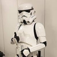
Received my pauldron from IG! As Devastator Squad Leader I feel like this is a necessary addition! I hope to make more progress on the armor this weekend!
.jpg.8afb2720fa17304defdd5b299b41f072.jpg) 1 point
1 point -
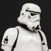
Adjusted the forearms, how do they look. Sent from my iPhone using Tapatalk1 point
-
Finally put together just needs the trimmings Sent from my iPhone using Tapatalk1 point
-
Another spectacular build. Great job1 point
-
Upgrades because… Since I am no longer working on a Sandtrooper, its just easier for me to keep all of my TK content on FISD. As previously mentioned, I posted this on MEPD but I am transferring it here for anyone who finds it useful. NOTE: this build thread outlines me using ½” thick Sentra as the base material; however, the Sentra snapped at the stock after I finished the build. In March 2019, I rebuilt the gun (a third time) where I used a planed down white pine board as the base material. Everything else is the same as you will see in this build. So, I recommend you use white pine, it weights less than the plywood and is more rigid than Sentra. Finding a ½” thick board is difficult. More than likely you will find ¾” boards at any Home Depot and you will need to plane them down to ½”. In my previous build I used plywood as the base material, and it is a bit heavy after trooping with it for any period of time. I also used Spool86's cast kit (heavily modified) for a lot of the parts. I like Spool86’s parts but they are not as accurate as I would like. Also, cast parts weigh more than 3D printed parts and this added to the overall weight. So, I wanted a more accurate and lighter weight T-21. To this end, I have modeled a lot of the parts and 3D printed them. I will make these parts available for free download from my Thingiverse page here: https://www.thingiverse.com/11b30b4/designs So, a few notes before we begin. The overall dimensions are very close to Pandatrooper’s diagram. I will be reusing the already made stock from my original RO T-21 and some of the other parts. I hope to re-use the barrel, but I will need to determine if it will mate with the new printed parts. Yoshix created a thread MEPD to discuss the RO T-21 differences but I had not seen it until now since most of my previous stuff was on FISD. A good catch was the space on the barrel before the rubber tubing. I did not build my previous T-21 with this gap in mind but I will endeavor to include it for this build. Another thing that has come up has been the discussion about the aerial gunner sight. Specifically, if it is an aerial gunner’s sight or as one of my friends has suggested that it is actually a coil cable (think phone cable) as a nod to the ANH T-21 and it is just sticking up oddly. What I am talking about is the red circles in these pics: I believe they are an aerial gunner sight and will be building my RO T-21 with this in mind. Although there are five different variants of the Lewis gun and there are a ton of different manufacturers of each variant I will be primarily using the MK1 variant. There are not a lot of pictures of the RO T-21 and the ones that I have found are lacking in detail. I have collected a large number of detail pictures of actual Lewis guns from across the internet to develop the 3D models. Although I could make a completely accurate model, there are a few areas I will need to divert from to make this something more buildable. One specific thing I have omitted is the underside of the cooling vent area mid-section of the gun. Seen here (yellow outline) is what was omitted for anyone wanting to go overboard in their build. There are a few other very minor details that I did not include in the 3D models but for the most part, they should be correct. I have embedded many of the roll marks seen on various pictures I have found. Most notably will be roll marks on the feed tray. For the base material of this build I will be using ½” (12.7mm) thick Sentra. I purchased a 4’x’8 sheet of Veranda HP brand PVC board from Home Depot for $69.00. Obviously, you will not need a whole sheet of this stuff but its hard to find in smaller quantities. Sentra is PVC board and Veranda is just a different brand. Keep in mind that I am working within the limitations of Tinkercad as I am not a CAD engineer. That being said, here are the models I have built so far. This is the main feed tray cover, mid-section cooling vents and vent housing. This is the center feed tray, ejector, feed operating arm, rear sight mount, forward feed tray, and assembly pegs. Receiver left side. Receiver right side. Rear receiver and stock mounting plate. I have already started printing these parts and here are some of the raw prints before finishing. I have a Prusa I3 Mk3 and I use MatterHackers MH Build series 1.75mm ABS filament. Some tips on printing: Any of the parts with horizontal holes or overhangs should be supported. I printed everything in ABS and to prevent any elephant foot (warping near the build plate) I printed everything with a brim. As for detail I used 0.07mm ultradetail with a fill of 15% for anything that had any detail. I printed the receiver rear and stock mounting plate at 0.10 detail with all the same settings for fill, brim, and support. Update 12/2/19 I have added a few additional 3D models to my Thingiverse for this build. First, I redesigned the rear sight mount. I added the rear sight with roll marks and adjustment knob and combined them with the receiver rear and stock mount plate I modified my T-21 transition to fit a Shop Vac Extension Wand (read further to understand why) and included the front radiator and flash hider, a backing for the radiator, the front end cap ring, and two barrel ends for the sides of the receiver. Lastly, I finished the models off with the two end caps for the oil brush that are mounted in the stock, the front sight, the trigger, and the gas key adjustment lever. Once I finished the models, I printed them, and they came out great. I should note that each file is printed in 0.07 Ultradetail which takes about 30 hours. After printing, everything got sanded and cleaned. After cleaning, everything got primer and then paint. Next, using Pandatrooper’s pattern and making some minor alterations, I cut the rifle out of Sentra. Once I had the shape, I started to dry fit parts and figure out where things would sit. Initially I was using a larger PVC pipe for the sides of the receiver and in these pictures, the lines you see where for the larger pipe. Here I was working out the trigger and test fitting the trigger guard. I reused the trigger from my previous T-21 but I have made a 3D model for anyone wanting to print one. Around this time, I realized the pipe I was using was a bit larger than I wanted so I found some ¾” SDR 21 PVC pipe which is irrigation thin wall PVC. I used this pipe along with a section of ½” Schedule 40 PVC pipe to make the side barrels on the receiver. I cut each pipe lengthwise in half then sanded them. Next, I drilled the ejection port and finished it with the dremmel. Next, I painted the ¾” pipes black and the ½” pipe silver. I glued the ½” pipe inside the ¾” pipe and then test fit them on the gun. Notice the remainder of the glue line under the new pipe, from the larger pipe I removed. This size pipe better aligns with the barrel part of the radiator. Next, I needed to replace the top aerial gun sight that is seen on the Rogue One version of the T-21. On my previous build I used an iron pipe I-bolt. Since reducing weight was one of my primary goals, I needed to find a new solution. I eventually decided to make the sight out of aluminum. I took some aluminum stock and worked it on my metal lathe. Next, I threaded the parts then cleaned the parts for painting. I also needed to remake the aluminum legs that protrude from the stock mounting plate and into the stock. Once everything was cleaned, I painted all the parts with a black bake on metal paint I use for gunsmithing. While the parts were baking, I took a hard look at my previous T-21 to determine what were the heavy parts. As I stated previously, the base of the T-21 was plywood and the switch to Sentra seamed to reduce the weight buy more than half. All the resin parts on the previous T-21 were heavy as well and switching them with 3D parts further reduced the weight. Switching from the Iron sight to an aluminum one reduced the weight; however, I soon realized that one of the heaviest parts on the previous T-21 was at the extreme front end of the gun, the 2.5” electrical conduit I used for the tapered bore of the barrel shroud was very heavy. I originally used this part because the outside diameter was 2.75”. I looked for a good replacement, but I had very little luck. I could special order a pipe with the outside diameter of 2.75” but most of the options were either too expensive, the wrong material like acrylic, had too thick a wall, or weighed too much. I was forced to consider a pipe with an outside diameter of 2.5” and again I was hard pressed to find a light weight option. Eventually, I found a shop vac extension wand a Lowes that had an outside diameter of 2.5” at one end and tapered to 2.25” at the other end of its 20” length. I only needed about 7” in length and if I measured the seven inches from the larger end the outside diameter of the smaller end would be just shy of 2.5”. The wand was fairly thin walled (about 1/8”) and very light. So about $8.00 this should work. I reworked the T-21 transition 3D model and included it on my Thingiverse page. So with all the parts gathered I continued to assemble the T-21. Next, I looked over the reference pictures and discovered that there are only two rings visible on the large part of the barrel shroud. One about 2” from the rear of the shroud and one with the front sight attached to it. There is also only one on the smaller part of the shroud at the extreme front of the barrel. So since I was reusing the barrel from my previous build I needed to remove some of the rings, fill some holes, re-score the exposed parts of the shroud and re-apply the rubber tubing. I used ¼” windshield washer tube for this. I added 4 mounting screw holes near the rear of the shroud that will be covered by the rear most ring and will make the barrel removable for easy transport. I still need to apply the feed tray parts and grips and finish painting then do a black/ brown wash over the whole thing to weather it but it is coming along nicely and the weight is amazingly very very light. I wish I had though to weigh the previous gun for a comparison, but I would say this thing will end up being 1/4 -1/3 the weight of the previous version. Update 12/5/2019 I assembled the radiator, flash hider, back plate, and end cap ring on the tapered part of the barrel shroud. Next, I installed the tapered barrel shroud to the transition then I dry-brushed silver on all the parts and attached the Feed operating arm, ejector, and the barrel ends on the sides of the receiver. I used E6000 to adhere the grip scales then masked off the radiator and bolt and applied a weathering wash comprised of black acrylic and light brown. Once this dried, I applied a flat clear coat over the whole rifle. I think the dry brush will look more natural in these pics. I did the black wash over the dry brush and it mutes the silver. I am inclined to agree with you about using bondo between the transition and the two parts of the shroud. The line between the transition should not be as defined; how that change will need to wait a bit before I can address it. For anyone interested the total estimated weight of the T-21 is 4.5 pounds. Back on topic, the stock is white pine, as are the grips. I made the stock for the previous version of the ROT-21 and re-purposed it here. The stock consists of two halves roughly ¾” thick and 8” x 18” once I have the outside rough shape, I hollowed out the interior with a router then glued the two halves together. The stain is Minwax Ebony with a satin clear coat on top. As for the strap, from the best images I could find I determined the width of the sling webbing to be 1.25” and the webbing to be black nylon webbing (most likely Mil Spec: MIL-W-4088 Type 10, Class 1A). At one time I made tactical gear and I am familiar with webbings and types. Some things to note from my research: In this screen grab you can see where and how the forward end of the sling is attached (Yellow Circle) and it looks to be an AK-47 sling mount screwed to the top of the barrel shroud just behind the front sight. Note the round (looks to be an areal gunner sight) sight just forward of the feed tray and is in the dead space of the barrel shroud between the two barrel shroud rings (Red Circle). Also note the rubber wrapped tubbing on the barrel shroud goes past and covers the middle barrel shroud ring (between the Red Circle and Yellow Circle). Lastly, note the rear sling mount appears to be on the side of the stock (Light Green Circle) and is most likely in the spot as the bras ID disk seen on some Lewis Guns. An assumption can be made that they are using an Uncle Mikes style sling mount and quick detach since this has been used on several weapons from Rogue One. I hope this build helps others out in making RO T-21s and feel free to ask question and/or point out anything I missed. Update March 2 2019 So Sentra was not the best idea I have ever had. The T-21 snapped where the stock meets the receiver when I snagged it going through a door. Since plywood was too heavy and the Sentra was too weak, I have rebuilt the rifle again using all the previous parts but this time I used a 3/4" white pine board that I planed down to 1/2" thick and seems to be holding up great and the weight is fine. Thanks for the interest.1 point
-
Hey Kalani, any way possible you can share this miraculous pigment source with me?1 point
-
Looking good, trooper! Good luck!1 point
-
Looking great William. Good luck with your approval !!1 point
-
Nice work and good luck with approval. Just watch the position of you drop boxes You may want to check the distance between the end caps and plate on your TD1 point
-
Great job William good luck on your application1 point
-
The best thing to do in this case is a hot water bath and carefully mold the calf armor closed and the Velcro is less likely to pull apart. Check out this thread and ask questions before doing anything. If you close that gap at the top of the calf armor, you should be golden.1 point
-
Hiya, For helmet padding, I’ve found tactical helmet pads to be perfect. I use four - forehead, left, right, behind head and this works really well for me. Still plenty of air flow. For darkening the inside I used self adhesive EVA sheets. Just cut them to different size strips and stick them in. This can be seen quite well in this video. :-) https://youtu.be/ao5xPPHtEXY Hope that helps. :-)1 point
-
If he's the same person I'm thinking of, he asked in the Anovos FB group as well, and I pointed him in the direction of the guy who used to do runs. It's a custom mix paint. Expensive, too, relatively speaking, but you don't need a lot just for shims and such. It works well:1 point
-
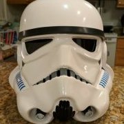
Completed ATA ABS helmet #1 as delivered to it's new owner. I hope this is a helpful guide for those building a helmet, it just takes some extra time and care and you can build an awesome helmet too.1 point