Leaderboard


Popular Content
Showing content with the highest reputation on 06/17/2023 in all areas
-
It's terrible to laugh at this, but I literally LOL'd out loud.4 points
-
Honestly, I think I'm speaking for a lot of us, when I say that I am so glad and thankful you're stepping up to manage all that. I'm pretty certain I couldn't do that. And you're not only doing it, but you're doing it super well. So thank you! And, yes, I'm one of those troopers3 points
-
Awesome, thank you for that quick response! I looks forward to hearing from the Deployment Officer Team about the issue as well. And I haven't added shims yet, so it wouldn't moving the bottom out so that the piece is level is still an option. I guess my biggest question is what takes priority, making sure that the back ridges are level or that the piece fits my leg correctly?2 points
-
Quick update after some minor blaster surgery. I mostly reassembled the E-11 so I could get a better understanding of where I can place the electronics. The muzzle cap had a large groove cut into it with a hacksaw and various Dremel bits to allow the installation of the muzzle flash device. I won't be using the kit barrel as it is really not needed. it can't be seen and leaves less room for electronics in the forward tube. I'm trying to place all the electronics in the main tube so I can keep the guts of the magazine in place I removed the installed fire selector switch in preparation for the BlastFX one. I found that the cocking action is very stiff and "grindy". You can actually feel and see little slivers of aluminum powder and shavings every time you weenie the action. This could be worked out over time, but I've never seen anyone cocking the action on an E-11 in the movies, so I don't need it here! Blaster is mostly reassembled. You can see that the selector switch is removed. I'll have to drill out the hole slightly to accept the post from the BlastFx version. I may also have to cut the post down slightly so the selector lever sits flush with the left side of grip body. And yes, I was listening the Gordon Lightfoot while grinding away. Something soothing about The Wreck of The Edmund Fitzgerald as you grind away at metal... I discovered a small issue with the end cap that I hadn't noticed before. The main tube has a grooved locking ring attached with 3 screws (visible in image) to the rear of the tube. This allows the end cap to lock into place. You basically line up little tabs on the inside of the cap with the grooves, push in slightly against the main spring, and turn clockwise. Once locked into place my end cap sits clockwise slightly, with the top being aligned at roughly 12:30 instead of 12:00. Locking ring on the Blasterfactory website. How my end cap sits vs how it should attach: On the real Sterlings there is a locking device (tab?) on the bottom just forward of the end cap. It has a spring and pivots when pressed which disengages a little tab that allows you to remove the end cap. Blasterfactory has included this little locking device with a spring, which is nice, but it is mounted about 1/4" forward of where it should be. It is also slightly off the bottom centerline of the main tube. Locking tab too far forward. The backend should overlap the end cap. There is a little stub on the inside of the locking tab that should sit in the small groove in the end cap. In the right image you can see the centerline of main tube in blue. My cap is locked in position with the center in green, and the black locking tab is off center in red. These "should" be easy fixes. Both the end cap locking ring and the black locking tab are held on with screws. I just have to re index everything and drill new holes. The muzzle cap surgery took a couple hours of cutting, grinding and filing down. I started with a couple simple hacksaw cuts with the muzzle held in a vice. I then used various Dremel bits to hack and grind away at the material. Thankfully this is aluminum and not steel! Unfortunately, the Dremel skipped a couple times and put some minor dings into the nice smooth paint job. These will be easy to sand out, but will necessitate a new paint job. Here it is basically done. I had to grind a small rounded bit out of the forward end of the slot to accommodate the led bulb of the flash unit. It's hard to capture in a picture, but I also had to grind a rounded groove at the bottom of the channel to accept the round circuit board of the flash unit. If I attempted to have the entire groove the depth needed for the flash unit, I may remove too much material and get close to the front sight cutout. Flash unit in the groove. The flash unit circuit board is a rounded "star" or "flower" shape, and one of the points / petals sits in the additional round groove at the bottom of the channel. In this pic, the muzzle piece is held upside down. So the muzzle sits just at the bottom (top in this pic) of the big hole. If I tried to center it I may remove too much material and get too close to the front sight groove. By me carrying out the surgery the muzzle flash board sits about 1/2 to 3/4" more forward. so it will be seen better. Back to the workbench!2 points
-
This is all in fun, as I have received several messages offering to help, but a lot of the time, this is how it feels. But that's okay, I enjoy my ability to give back to the detachment.2 points
-
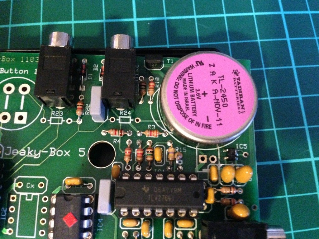
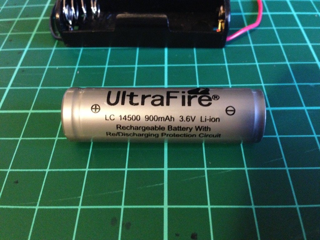
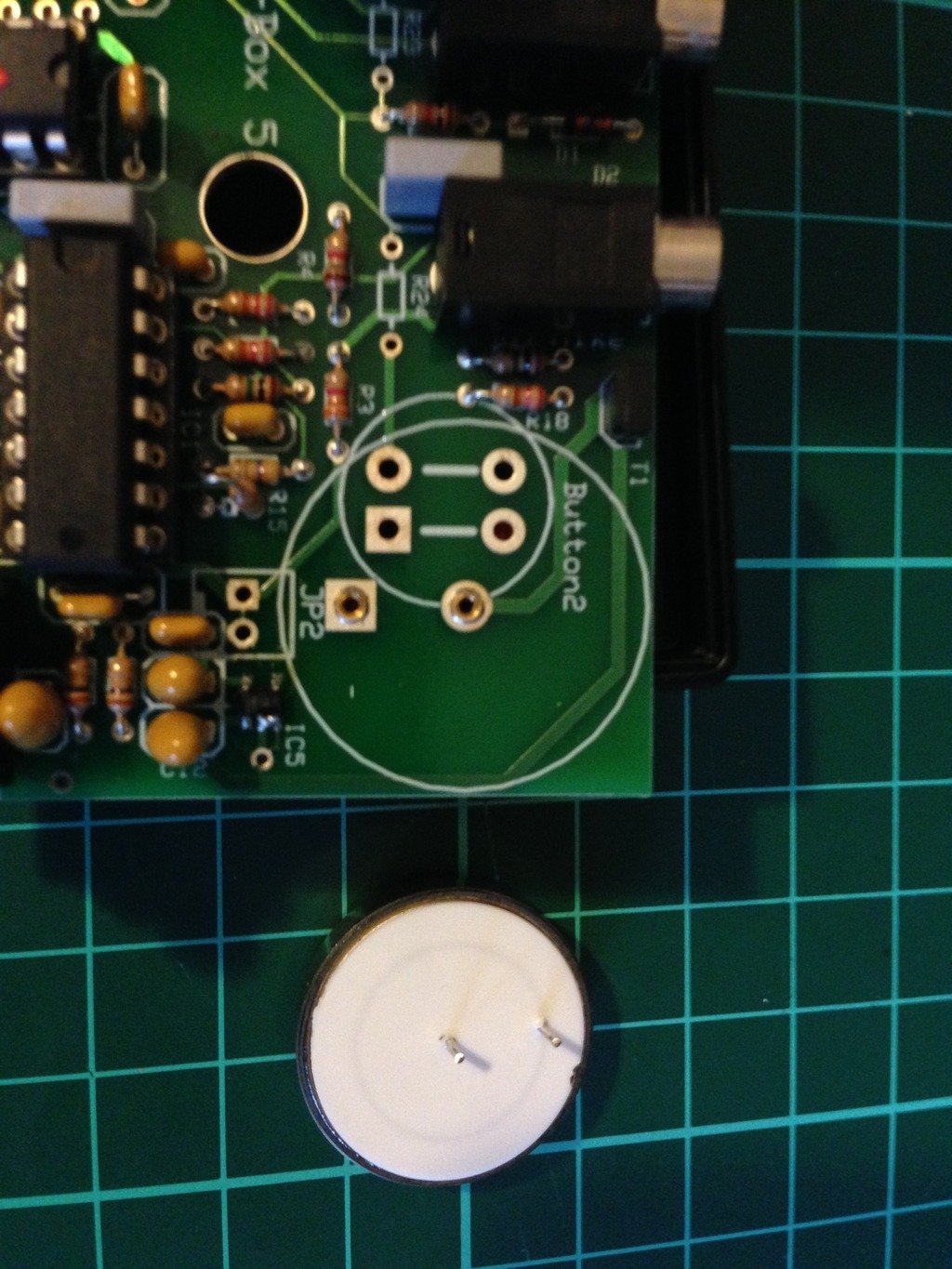
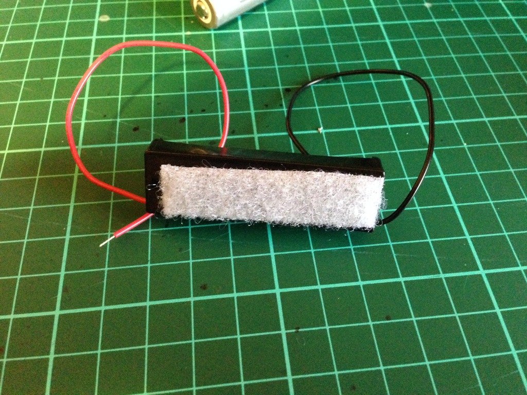
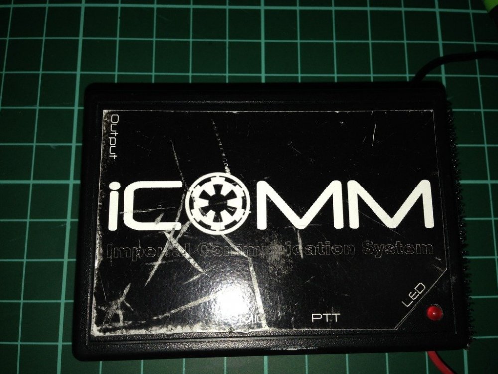
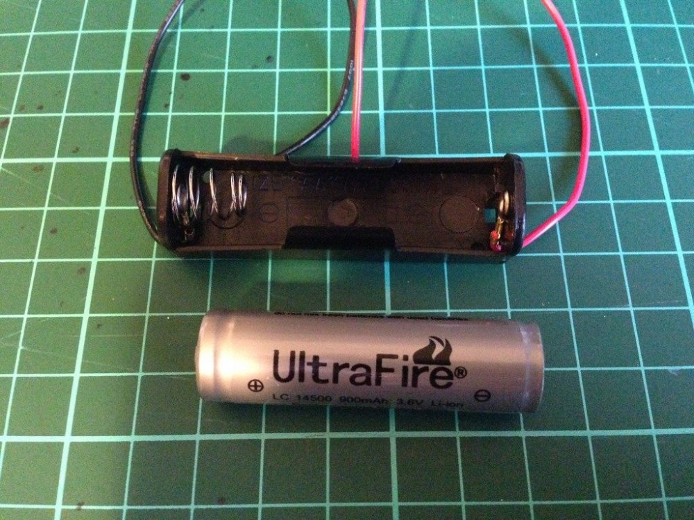
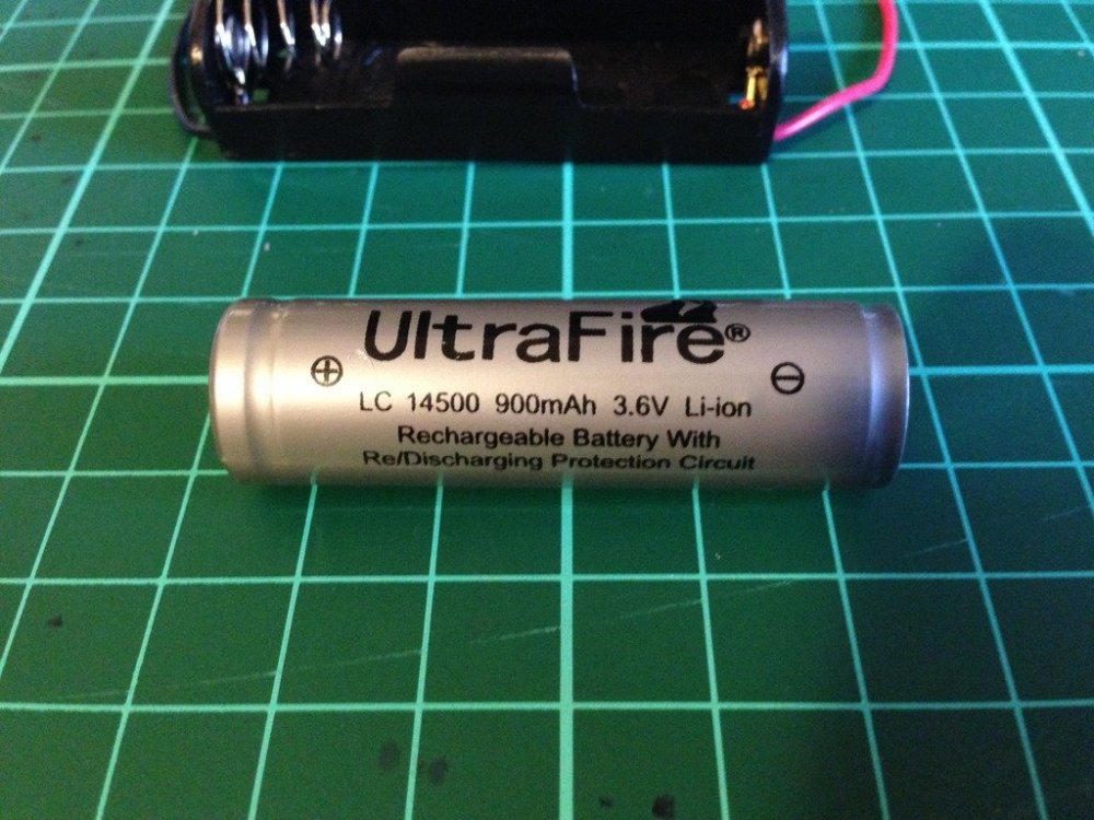
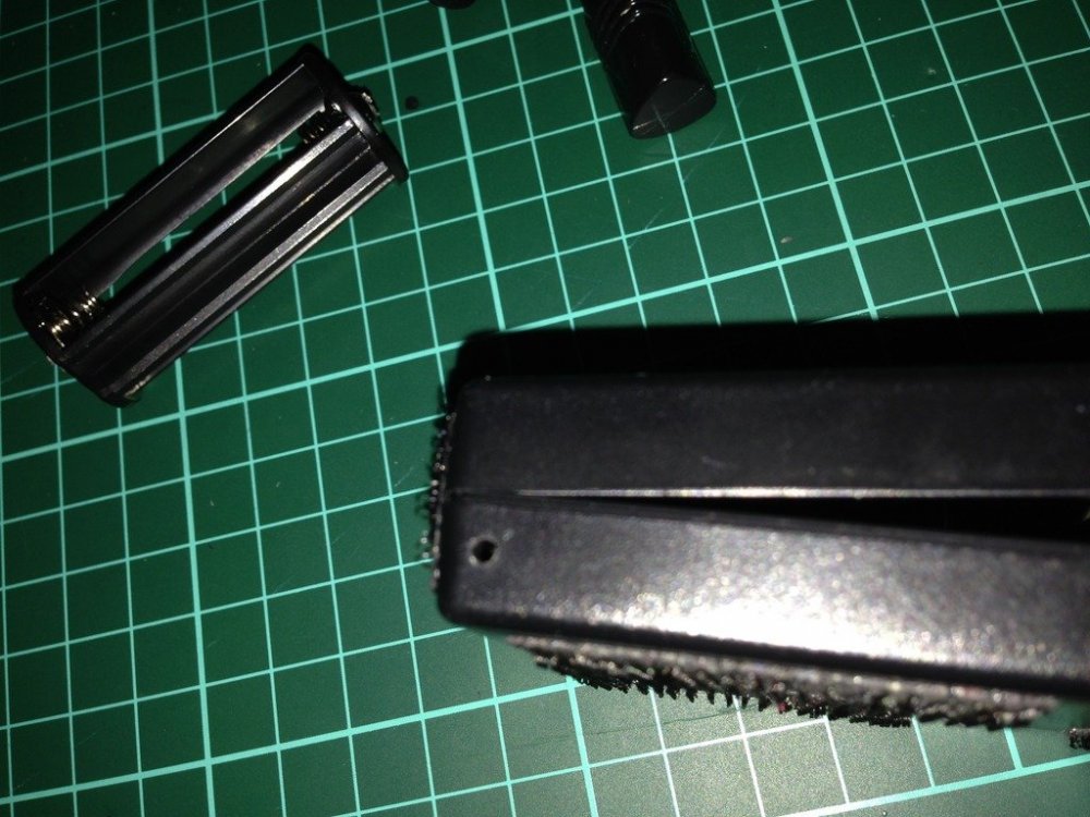
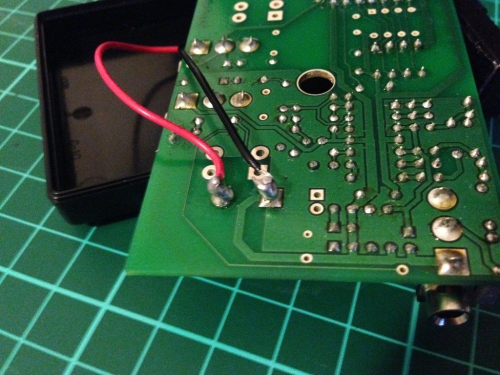
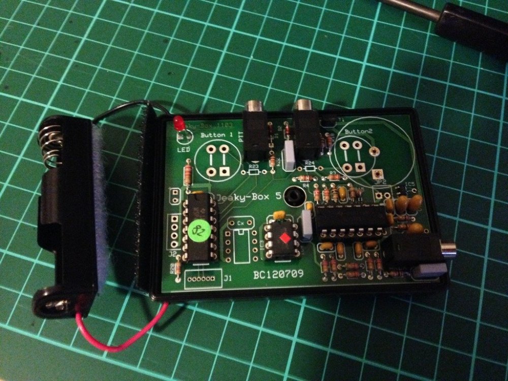
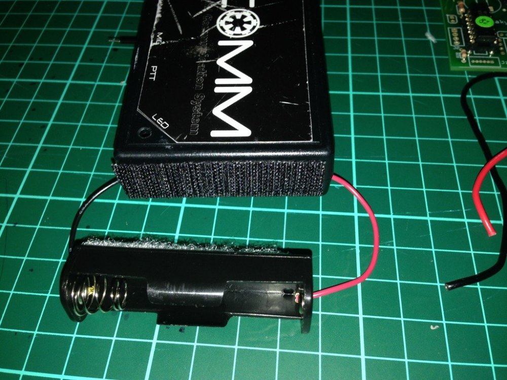
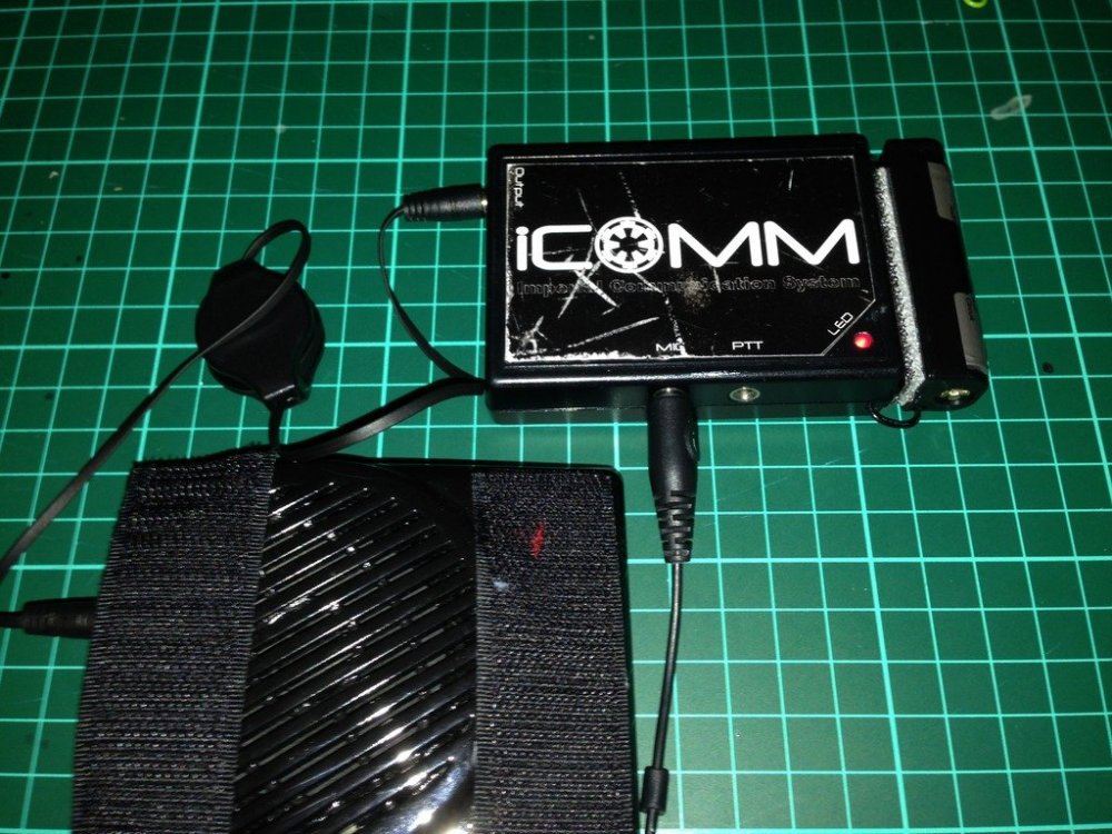
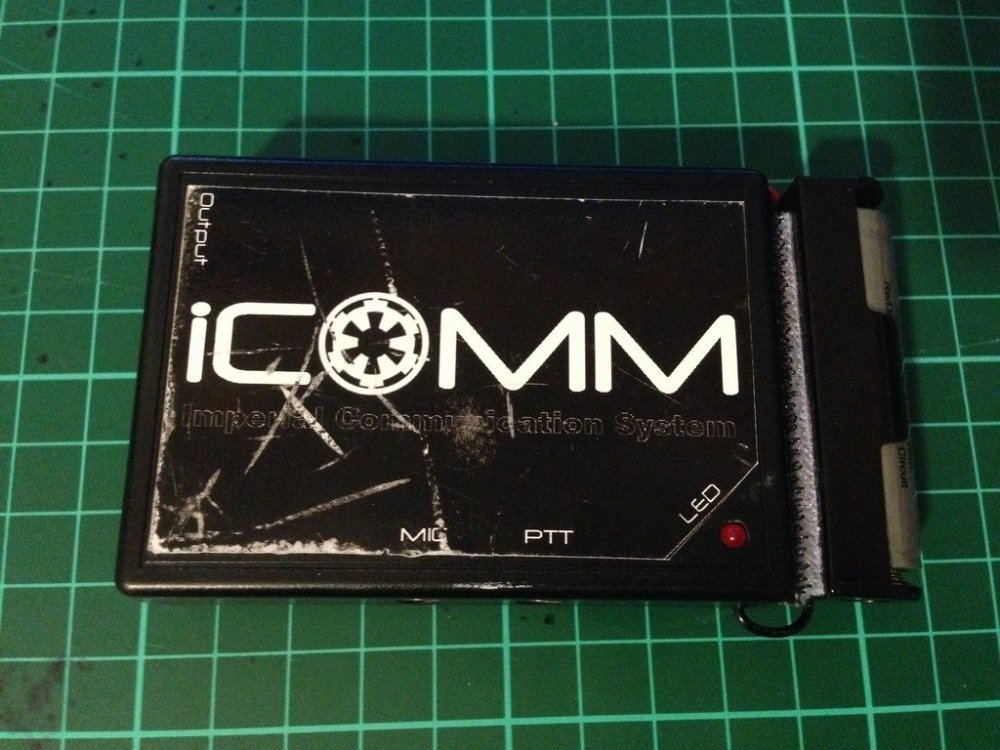
The humble iCOMM, works well while the internal battery is good, but after a year or so..........they stop working. How to tell, its the iCOMM battery. If the little red light no longer comes on and the static burst is not sounding, there is a good chance it is just a flat battery. Image has been scaled down 42% (600x450). Click this bar to view original image (1024x768). Click image to open in new window. Internal iCOMM battery Image has been scaled down 42% (600x450). Click this bar to view original image (1024x768). Click image to open in new window. Freight is expensive to get the very specific battery that is inside. Genuine replacement batt $5 US, freight, $25 US. Whattt!!! $30 US.... for a battery.....at least that's what I said. (approx $38.40 AUS) So I decided to do a little research, and come up with a reasonably simple and inexpensive mod, approx $12-$15 Aus. A simple AA battery holder and a rechargeable Lithium ion battery. Image has been scaled down 42% (600x450). Click this bar to view original image (1024x768). Click image to open in new window. Not just any kind of rechargeable battery can be used. The iCOMM is sensitive to voltage, so a 3.6 volt battery is required. The milliamp hour rating, or how much draw per hour on the battery, is only 560mAh, not bad for its small size, but I have replaced it with a 900mAh, so almost twice the capacity, and rechargeable. Approximate lifespan......Years and years. I chose to go with a battery with an internal protection circuit, as Li-ion batteries are finicky with charging. (have been known to EXPLODE). A digital battery charger, designed to suit 3.6-3.7 volts is perfect. Available on evilbay for as cheap as $5 shipped from China Image has been scaled down 42% (600x450). Click this bar to view original image (1024x768). Click image to open in new window. As I discovered during the research phase, the internal battery is easily removed. Image has been scaled down 42% (600x800). Click this bar to view original image (1024x1365). Click image to open in new window. First I added some adhesive Velcro to the back of the battery holder. Image has been scaled down 42% (600x450). Click this bar to view original image (1024x768). Click image to open in new window. Then I drilled a couple of small holes, one in either side of the bottom half of the iCOMM casing. Image has been scaled down 42% (600x450). Click this bar to view original image (1024x768). Click image to open in new window. Thread the red +, and black - ,wires through the holes of the casing.(From outside through to inside) When you flip the circuit board of the iCOMM over you can solder the wires to the corresponding posts. The outer most post is the positive (+) and the inner post the negative(-). Image has been scaled down 42% (600x450). Click this bar to view original image (1024x768). Click image to open in new window. Flip the circuit board back over and fit back into the case. Please note, you will actually have to fit the circuit board back into the top part of the case as it is the half that has all the plug holes and LED hole. Image has been scaled down 42% (600x450). Click this bar to view original image (1024x768). Click image to open in new window. Place the two halves together, put the screw back in, and add the opposite half of the adhesive Velcro to the end of the iCOMM. Feed the wires in through the holes to keep the excess out of the way. Image has been scaled down 42% (600x450). Click this bar to view original image (1024x768). Click image to open in new window. Tested for success, my iCOMM is again fully operational. Image has been scaled down 42% (600x450). Click this bar to view original image (1024x768). Click image to open in new window. As you can see, the overall size hasn't changed too much. iCOMM 8cm long, iCOMM with external battery adaption, 10cm long. The weight has increased by only 20 grams. Image has been scaled down 42% (600x450). Click this bar to view original image (1024x768). Click image to open in new window. Parts List and cost Battery Holder AA size $1.00 UltraFire Li-ion battery $6.00 (Protected circuit) Digital battery charger $5.00 miscellaneous bits $3.00 Battery holder from Jaycar, all other parts from ebay. Please note: These prices were in Australian $, so would be cheaper again in US$


 1 point
 -
Battery is a 3.6V AA 900mAh battery, I have used higher mAh batteries with no issues, as long as the AA is a 3.6v Quick searches: AMAZON Battery https://www.amazon.com/s?k=3.7v+aa+rechargeable+battery+900mah&crid=16GDRDQOUHXJS&sprefix=3.7v+aa+rechargeable+battery+900mah%2Caps%2C348&ref=nb_sb_noss Holder (I've only seen packs of 6-8) https://www.amazon.com/Single-Battery-Holder-Leads-5-Pack/dp/B07THZL8JX/ref=sr_1_4?crid=1MKB3I92U4Y5Y&keywords=1+x+aa+battery+holder&qid=1687043446&sprefix=1+x+aa+battery+holder%2Caps%2C357&sr=8-4 I also find Aliexpress to be a cheap option for electronic parts ALIEXPRESS Battery https://www.aliexpress.com/w/wholesale-aa-rechargeable-battery-900mah.html?catId=0&initiative_id=SB_20230617151237&origin=y&SearchText=aa+rechargeable+battery+900mah&spm=a2g0o.detail.1000002.0 Holder https://www.aliexpress.com/item/1005004016852718.html?spm=a2g0o.productlist.main.13.5666308epE6EqW&algo_pvid=9fffd0d4-849f-4c08-abc3-88cb6227642a&aem_p4p_detail=202306171611552896936901680680009541166&algo_exp_id=9fffd0d4-849f-4c08-abc3-88cb6227642a-6&pdp_npi=3%40dis!AUD!1.18!1.18!!!!!%40211be54b16870435154592879d07ff!12000027750189299!sea!AU!178098435&curPageLogUid=LAY2qcH0djVl&search_p4p_id=202306171611552896936901680680009541166_71 point
-
Sorry for the confusion, there is no lower ridge modification in those threads, it was more to show the adding of shims. As you can see from the reference below standard the lower ridge is pretty straight standard Making your modification the lower ridge is angular, some GML's may not allow this even if that is how it has to fit you, I have seen an application which had to be modified so this lower ridge is straight after enlarging. Another application I had previously seen added the width shim all the way down and included extra material for the lower ridge. At the end of the day it is your GML who will either approve or deny so always best to check with them and for higher level approval it's up to our @Deployment Officer Team, hopefully they will chime in soon with what they will allow1 point
-
@jsilvius Ping ping ping ping!1 point
-
Wiki Doc back end is constructed, haven't fleshed it out as yet but intro title is complete
 1 point
 -
As we have more interested in building this costume, hopefully we can finally get this one over the line.1 point
-
Dude I’d totally jump on a merch run for/with you. I love puzzles and enjoyed compiling the pin interest thread quantities for you. =) Sent from my iPhone using Tapatalk1 point
-
I just finished painting my TFA anovos bucket lol good timing. Almost done armor is painted; just need someone to make me a cape and my soft goods to show up...1 point
-
awe... flattery will get you everywhere... LOL Thank you, I do appreciate the kind words.1 point
-
This thread right now1 point
-
1 point
-
1 point
-
I lived in the UK (Lancashire**, but don't hold that against me, lol) and I can say from experience that the humidity there is not quite what it can be in Florida at times (97% as I write this). Being an accuracy nut I would love to wear rubber gloves at all events, but emptying them every 20 minutes can get a bit tiresome. **1 point
-
Authentic gloves when it's cold. Authentic gloves when it's hot. Authentic gloves all the time.1 point
-
I received my BBB 6/10/23. It's a WTF suit. I already have my helmet, E11, and boots from my previous suit. I started trimming the forearms yesterday.1 point
-
Indeed! That would be great!1 point
-
Nomex pilot gloves sir. 1 set is now 68ish troops strong. I use some junk called AnyGlove on the fingertips of mine to let me take selfies.1 point
-
I'm 184cm tall, and 70kg, overall, a skinny guy, and i use padding in the arms, not the torso neither the legs. In my case i do not need to trim the armor. I hope my example helps in some way Sent from my GM1900 using Tapatalk1 point
-
Good Lord, why cant they just make up their minds and stick to the original time lines!! To the average cos player it probably makes no difference but to Legion where we do our darnedest to follow the movise and time lines as depicted by the artists and writers, this is just a headache.1 point
-
So change in direction. I decided to take a shot at just modeling my own abs in Fusion360, and then using Blender to scult in the more organic curvature. This way it will make it a lot easier to make adjustments and corrections to the model as necessary. This makes it easier to split the abs up into printable pieces, where I can build in registration for putting it all together. I can then model the belt, ab boxes, etc straight off the abs to make sure everything works together well. This is the first pass at the model for the abs. Started working on the chest plate as well. Still a work in progress. Question on the belt: How tall is it? In some photos the belt seems larger than others. In trying to figure it out I went so far as to hold up a ruler to the screen and try to measure the belt in comparison to the ab boxes. Using this highly technical process, it seems to be that the height of the belt (not counting teeth) seems to be pretty close to the height of the center ab box. Is that close?1 point