Leaderboard


Popular Content
Showing content with the highest reputation on 06/14/2020 in Posts
-
Fixed! @TheSwede Thanks for the fix! The straps are 1 inch across3 points
-
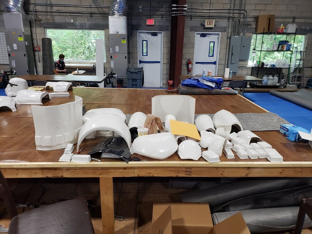
I've been slowly working on a 3D print build of Nico Henderson's R1TK helmet. Nico is well known for his accuracy on his Shoretrooper helmet design, so when I saw him post on Facebook that he was going to be releasing a 3D printable model of the R1TK I knew I had to give it a try. It's a beautiful design and I believe it to be the most accurate I've seen. I didn't know how far I was going to get with this build tbh so I hadn't started a build thread, but now that I'm getting close to painting I figured now would be a good time to post my progress. I'll probably need some advice on paint here soon as well, so any advice on paint and/or threads to read would be appreciated!! Here are some pics of the freshly printed pieces: And here's a few of the mockup of the raw printed pieces (except for the chin and ears which I had already started to sand): So after I had sanded things down a bit, I wasn't sure which method I wanted to use to fill the print lines I couldn't get with sandpaper. I had heard some people talking about using XTC3D so I decided to give that a try. My opinion is that it's good if you don't want to process it too much further than the initial polish, but I ended up with bubbles in the dried resin and found it difficult to sand, I think I could've gotten the same results easier just using filler primer, which is WAY easier to sand and get smooth. After endless hours of sanding I was finally ready to attach some of the pieces together. I started with the face and the back, then attached the dome. I wanted to fill the seam line between the back of the helmet and the dome. I wasn't ready to attach the chin yet as I wanted to get the face/back/dome piece as well as the chin up to paint ready smoothness with wet sanding before I attached the rest of the face together. Mostly so I wouldn't have to try and sand the seam between where the chin and cheek tubes meet, as well as the surfaces leading into the frown. So finally, I'm caught up to my current progress. I've got everything wet sanded up to 2000 grit and I have attached the chin to the rest of the helmet. I've mocked up the ears, brow trim and vocoder for looks, everything else you see is attached. Now I need to know how to proceed with painting. I've been trying to research rattle can options and the steps I should follow. I've never attempted to spray paint a project that needed to achieve the level of gloss and smoothness that this requires, so I want to get all the input I can before I proceed. I'm not sure if I should be laying down a particular type of primer first (should I use white primer?) and then what type of paint is best and how I should be going about getting all the angles without missing spots or pooling problems. Also, I've seen people talking about just using gloss white, but then I saw someone mention appliance epoxy, which I think might be a good idea due to the fact that it resists chipping? I found some at my local Home Depot but wasn't sure so I haven't gotten anything yet. This is what I found: Alright, well I'd love to get some feedback on the painting process as well as how to proceed with painting the greeblies (tears and traps) as well!2 points
-
Don't overlook the awesomeness of baking soda and CA glue to make CA cement as a filler. Have you tried it yet? It cures the CA glue almost instantly and fills, resulting in a weld stronger than the parts themselves. And it sands like a dream. I applied a small bead of glue to the inside edges of the parts, then apply another more liberal bead to the inside (hidden) surface areas when you hold the parts together. Typically I would tape off the outer areas to help keep the parts lined up and to reduce oozing on the outside of the part. Once the liberal bead of CA glue is applied, then generously sprinkle the baking soda all over the bead while holding the pieces together. I apply enough so that I can smoosh it down with my finger (wearing gloves) and along the bead line, pushing the baking soda into the joints a little bit. It really works nicely.2 points
-
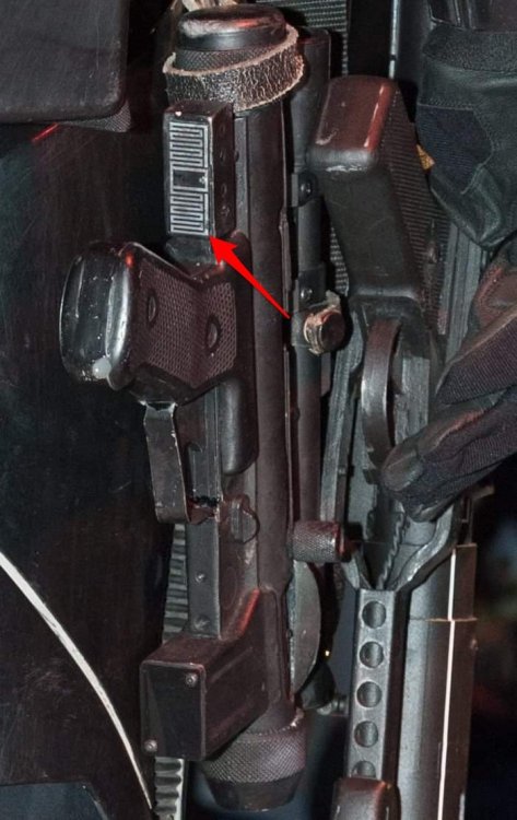
The E-11 blasters in Rogue One, or any Disney Era E-11 are most similar to the E-11 blasters in A New Hope, however there are actually several differences. Some are just minor differences, and some are more significant changes but every aspect of the blaster is different is some way big or small. Our detachment commander has requested that I start a thread and list the differences so this will serve as a 'Blaster Reference' for the Rogue One BlasTech E-11 (often mistakenly referred to as the “E-11B” which is not correct or canon). The Rogue One Stormtrooper CRL is currently being developed for our detachment and there will be specific requirements concerning the blaster details similar to any other stormtrooper CRL. I will list the differences and show examples as best as I can. I'll start off with this image from the Rogue One 'Ultimate Visual Guide', a very nice hard cover book full of great photos and information. And a higher quality version of the same photo, I believe this is the Hero Prop. Here's a list of all the parts and how each component on the R1 version differs from the ANH version. 1. The Base Gun The E-11 blasters in R1 are based on an airsoft S&T Sterling L2A1 AEG. The E-11 blasters in ANH were based on a real 9mm Sterling Mk4 L2A3 SMG (Sub-Machine Gun) 2. The Scope The Scope used in R1 is a 1943 M38 Telescope made by M.H.R. Co (Minneapolis Honeywell Regulator Company). The Scopes in ANH were mostly 1942 M38 Telescopes though at least one '43 can be spotted in the film too, they also used model M19 telescopes in ANH as well. The main difference between them is that a '43 has a wide front foot and a '42 has a narrow front foot. 3. The Counter The Hengstler counter used in R1 has a small (mini) eagle logo and the more common plastic socket cover. The Hengstler counters used in ANH all had the medium or large eagle logo and the rare vintage metal socket covers. 4. The Power Cylinders/Rangefinder/Targeting Sensor The Power Cylinders used in R1 are believed to be taken from a SDS (Shepperton Design Studios) E-11 Blaster. This blaster is widely known to be inaccurate here on whitearmor.net and the power cylinders on it are nothing like the originals seen in ANH as it claims to be, the SDS power cylinders are a very unique design. The Power Cylinders in ANH are an unknown found part taken from electrical equipment that has yet to be identified to this day. 5. The T-Track The origins of the T-Track used in ANH is also unconfirmed, however the T-Track used in R1 looks noticeably thicker than in ANH. I believe the T-Track used in R1 was taken from an SDS (Shepperton Design Studios) E-11 Blaster similar to the power cylinders. 6. The Scope Rail The scope rails in R1 appear to be mounted a bit higher than they were in ANH. The rails in R1 are also mounted somewhat differently, often with a block and screw type design. The rails in ANH utilized a bent tab at the front seated into the first receiver hole and another tab screwed to the rear sight aperture or riveted directly to the receiver. 7. The Flashlight Last but not least and probably the most significant change aside from the airsoft gun or power cylinders is the addition of an entirely new greeblie on the right side of the blaster; an Element M300A Mini Scout Light (Airsoft replica of a SureFire M300 Tactical Flashlight) 8. The Flashlight Rail The flashlight is mounted to the right side of the airsoft gun through the receiver holes using a short 3-slot picatinny rail. There are many short 3-slot picatinny rails available but the screen used one has sharp corners with a rounded groove on the back surface to mount flush against the side of the airsoft receiver tube. 9. Extras Some E-11 blasters in Rogue One have extra little differences, nothing significant but there are a few small noteworthy things that are not consistent across all the E-11 props. 1. The Base Gun It is immediately fairly evident that the prop department had to use whatever was readily available at the time, due to production deadlines, filming schedules, ect. I was personally building an all metal E-11 blaster during the production of Rogue One and I can assure you that sourcing metal parts was very rare at that time, even replicas let alone vintage ones! There were not many options for E-11 builds then and mostly everything available were resin casts, it was pretty sad. I actually ended up resorting to the exact same steel Airsoft Sterling that the prop department at Lucasfilm did for Rogue One; The S&T Sterling L2A1 AEG. Most of the blasters seen in the movie along with most promotional media images are actually a resin or rubber cast, But I believe the one in this image below to be the master 'Hero" prop with the steel airsoft gun, real flashlight, ect. You can see through the slot for the charging handle that the receiver is actually hollow, and you can see the receiver holes that the ends of the T-Track are inserted into. Also notice the thickness of the folding stock. This prop would be used for closeups and such while the rubber casts would be used for background extras and stunts or any kind of considerable action where there is a concern for the actor's safety. Here is a resin casting of the Rogue One E-11 blaster, notice the charging handle slot, receiver holes and the thickness of the folding stock. The airsoft S&T Sterling L2A1 AEG is different than a real 9mm Sterling Mk4 L2A3 SMG in several ways, some greater than others. The airsoft gun is a close representation of a real Sterling meant for recreational sport, it was never intended to be an exact replica, It's fairly close but some of the dimensions are different. It should also be noted that S&T actually produced a limited edition "E-11 Blaster" version of this airsoft gun, though this is not what the prop makers used in the film nor is it accurate to any E-11 used in any Star Wars film ever. The prop makers for Rogue One started with the standard S&T Sterling L2A1 as a base for the E-11 Blaster. The main differences from a real Sterling are in the Grip, the Rear End Cap, Muzzle Cap, and the Folding Stock. Like I said before there are many other differences too but I will just focus on the most obvious ones for identification purposes. As you can see the Airsoft Grip (top) is much more square and also a bit bigger than the real Sterling Grip (bottom). The airsoft gearbox is right above the trigger which is why it looks much bigger and more 'bull-nosed' than a real Sterling trigger group. The selector switch on the airsoft is thicker and the letters for the selector switch are also in a different order. And the other side. Airsoft (top), Sterling (bottom) The next most significant difference is the Rear End Cap or the "Blaster gas cylinder cap" as it's referred to in the Rogue One visual guide. The Airsoft (top) is bigger and bulkier than a real Sterling (bottom) which is actually tapered towards the front of the gun unlike the airsoft version. Also the airsoft is pointed in the bottom back corner where the Sterling is rounded. The Muzzle is fairly close but there is a difference. The Airsoft (top) has a sharper edge than a real Sterling (bottom) which has a rolled edge. Also the hex bolts on the real Sterling have a diamond cross hatch knurling pattern and the Airsoft ones have a standard spline knurling pattern. The barrel hole is clearly smaller on the Airsoft due to the difference in caliber to a real 9mm Sterling sub-machine gun. Also the receiver holes on the airsoft are slightly smaller than a real Sterling and the bayonet lug is different as well. The Folding Stock is also fairly close but again there are some differences. The Airsoft (top) has bends that arch inwards where as real Sterling (bottom) has bends that arch outwards. The real Sterling also has a small block on the end of the support bar at the base of the 'Y', this block is completely absent on the Airsoft folding stock. The real Sterling folding stock is also made of thicker steel than the Airsoft one is. The Airsoft folding stock is mounted with slotted bolts and the real Sterling folding stock is mounted with carriage bolts. The only real permanent modification the prop makers made to the Airsoft Sterling was cutting down the length of the magazine to be much shorter and removing the internal components. They also added a dome headed hex screw to the existing hole in the magazine bottom plate. Unmodified Magazine Length. Modified Magazine. Dome headed hex screw in magazine bottom plate. They also drilled a hole in the Bayonet Lug as a forward Sling Attachment point, however this was not the only method but more on that later. 2. The Scope Like the original scopes in ANH, the scopes in R1 are also M38 Telescopes, although for the most part a different model year was used. They are both a found part taken from an M4 Sherman Tank Periscope. The scope or "Targeting Macroscope" as it's referred to in the Rogue One visual guide is a 1943 M.H.R. Co M38 Telescope while the E-11s in A New Hope had 1942 M38 or M19 telescopes. Although at least one 1943 M38 can also be spotted in ANH as well. The main difference is that the 1943 M38 has a tapered front foot where as the 1942 M38 has a straight front foot. The '43 also has a gap between the prism housing and the front foot where as the '42 does not. Here is a 1943 M38 (top) and a 1942 M38 (bottom). Notice the difference in the front foot on both scopes. Front view of a 1942 M38 (left) and a 1943 M38 (right). Notice the front foot on '43 is tapered and the '42 is straight. This is a photo of a screen used resin cast scope. Notice the year in the engraving, this confirms a 1943 M38 was used. The serial number on this screen used scope is No. 110332 as you can see. Below is a confirmed photo of a DoopyDoos resin cast M38 scope, notice the matching Serial No. 110332. These resin kits from DoopyDoos are very common, the prop department seems to have used whatever parts were readily available for all of the E-11 components. It is difficult to confirm if the scope on the steel airsoft based 'Hero' prop is actually a real metal one or not. Though due to this discovery I assume it is a resin cast as it is highly unlikely that Lucasfilm is in possession of the original M-38 Scope that DoopyDoos made their molds from. 3. The Counter The Hengstler counter used on the R1 E-11 is similar to the originals used on the ANH E-11 aside from a few key differences. The counter used in R1 has a small (mini) eagle logo and the more common plastic socket cover. The counters used in ANH all had the medium or large eagle logo and the rare vintage metal socket covers. It should be noted that the plastic socket cover in R1 is modified to have a window cut-out for the eagle logo. You can clearly see the mold injection points which confirms a plastic socket cover was used instead of the original metal socket cover. Also the counters in R1 have the wire terminal connectors removed and in ANH they are still attached. Here is a comparison photo of the three different eagle logos that have been used in Star Wars movies. The first small eagle on the left was used in R1, the medium and large eagle logos were both used in ANH (middle, & right) It should also be noted that these all have two screws, any versions of the eagle logo with only one screw are not screen accurate though they are much better than using Hengstler's current "H890" logo. This photo shows an unmodified plastic socket cover on the left, and on the right is a modified plastic socket cover with a window cut out for the small eagle logo. Here is another photo of a plastic socket cover modified with a window cut-out to expose the small eagle logo. Similar to the scope it is difficult to confirm whether or not the counter on the 'Hero' prop is actually a real one or not. Though I assume it is a resin cast as well. The Counter is attached to the blaster using a Bracket mounted to the scope rail between the scope feet. The image below is actually a screenshot from The Mandalorian but it is the exact same prop that was used in Rogue One as well as the SOLO movie (Disney Era E-11) Notice the Counter Mounting Bracket visible under the Scope. The Counter Bracket is actually a sideways 'T' shaped bracket with 4 Hex screws holding it to the back of the counter. Then the Counter Bracket is mounted to the Scope Rail with 2 Hex Screws. If it helps to demonstrate; here is a blaster with the Counter & Mounting Bracket, and another blaster without the Counter & Mounting Bracket. It should be noted that all the blasters in the film appear to have counters on them, I cannot see any that are missing in the movie. 4. The Power Cylinders These are images of screen used power cylinders from Rogue One. The power cylinders in R1 are very different than the original ones seen in ANH. Here is a comparison photo of both kinds. Rogue One on the left, A New Hope on the right. The original power cylinders in ANH were cut from racks like this one, the origins of which have yet to be discovered to this day. These cylinders were used on many other props in ANH aside from the E-11. including the hood of Luke's Landspeeder as seen here, The MSE Mouse Droid, The targeting systems in the Y-Wings, and Luke's X-Wing while approaching Degobah. The power cylinders in Rogue One are believed to be taken from a Shepperton Design Studios E-11, another example of the prop department using whatever was readily available. These blasters are made of plastic infused with a dense foam filler but the power cylinders were most likely recast in resin or rubber for the movie props. The SDS E-11 blaster is widely known to be considerably inaccurate here on the forums, and the power cylinders on it are definitely not cast from original parts as it claims to be. The fact that 40 years later they've now been used on screen in a star wars movie is an ironic coincidence, and one that takes place before the original at that. Long story short Andrew Ainsworth at Shepperton Design Studios was involved in a lawsuit from Lucasfilm Ltd. for public sale of stormtrooper armor without licensing rights. Liz Moore and Brian Muir sculpted the original stormtrooper design which is owned by Lucasfilm Ltd. Andrew Ainsworth being a maker of canoes and fish ponds at the time was contracted by the costume department to mold Liz & Brian's sculpts into HDPE plastic for the original Star Wars production back 1976 (film released in '77) To be clear Andrew Ainsworth at Shepperton Design Studios did not assemble the original armor or any other screen used movie props for that matter. That was all done at Pinewood Studios including the E-11 blaster. Andrew Ainsworth only molded and cast the armor pieces, he did not sculpt them, it's not his design, and he did not assemble them. Here is a confirmed photo of the power cylinders on a Shepperton Design Studios E-11 blaster. Again these Shepperton Design Studios blasters are made of plastic infused with a dense foam filler. However the power cylinders seen onscreen were likely not taken directly from the SDS E-11, but rather borrowed the design and recast in resin or rubber by the prop department. Notice the air bubbles/voids on the front of these power cylinders, clearly a recast with obvious casting defects. They are also slightly smaller than an actual pair of SDS power cylinders. The prop department also removed the coiled wires and added a second screw for stability. 5. The T-Track These are images of screen used T-Track from Rogue One. The T-Track used in R1 is noticeably thicker than the original T-Track in ANH. Here is a comparison of both; R1 on top and ANH on the bottom. The origins of the T-Track used in ANH is firmly believed to be hard black plastic T-Track from old cupboard sliding doors. This same T-Track was also used on several other props in the original trilogy such as Boba Fett's EE-3 Blaster as well as various Lightsabers. The T-Track used in R1 is believed to be the exact same kind used on a Shepperton Design Studios E-11 Blaster, it is sourced from a company in the U.K. called Tubeway Sales LTD. It is called "Insert Track" and it is designed for sliding doors, this T-track is sold under the product code: ER060B8. https://www.tubewaysales.com/cat/plastic-trims-and-miscellaneous-items/plastic-insert-and-t-track/ If you want to buy this T-Track contact Shear Tech on Facebook; https://facebook.com/sheartech or [email protected] Alternatively you can also contact 3D-Props and inquire about buying Rogue One T-Track from them; https://www.3d-props.com/contact/ Like the SDS power cylinders this T-Track is quite unique. Here are confirmed photos of the T-Track on an SDS E-11. Here is a photo of screen used T-Track from R1. Notice the thickness and shape of the fins on the T-Track match that of the SDS T-Track above. The ends of each track have also been trimmed/modified to fit the receiver holes on the airsoft gun. Here is a photo of a resin cast blaster with the flashlight missing, notice how the T-Track is not covering these receiver holes to allow for the weaver/picatinny rail to be monuted. This is very different to the way the T-Track was installed in ANH as there were no flashlights on the blasters in that movie. Other than this difference, the T-Track is installed the same way as in ANH; T-tracks covering all rows of holes except the bottom left row with the bayonet lug. Also the first receiver hole on top is left open to mount the scope rail, and obviously the very bottom row of holes under the folding stock is also left uncovered. 6. The Scope Rail The scope rails in R1 are fairly different than ANH in the way that they are mounted to the blaster. For the most part the E-11 blasters in R1 use a block and screw type design while the blasters in ANH use a bent tab type design. The majority of the blasters were resin cast which also use the block and screw type mount. There is also this alternate rail mount which is possibly a rubber cast if not resin. The front has a post and screw type design as well as a 90 degree bend in the rail while the back has a "Z" bend screwed directly to the blaster between the rear sight guards. Then there is the 'Hero' prop that the rest were cast from, based on the actual steel airsoft gun and other real parts. This particular prop has more of an original ANH style rail mount though it is taller than the ones in ANH. The front of the rail uses the same bent tab type design which is seated into the first receiver hole. The back of the rail has a "Z" bend where it is mounted to the rear sight aperture, some of the rails in ANH had a similar "Z" bend although they were riveted directly to the receiver just in front of the rear sight guard. Most of the rails in ANH were screwed directly to the rear sight aperture except they were flat in the back and mounted much lower than R1 without this "Z" bend. 7. The Flashlight Last but not least and probably the most significant change to the E-11 aside from the airsoft gun or power cylinders is the addition of a flashlight on the right side of the blaster. There were no flashlights used on the E-11 blasters in ANH whatsoever. The flashlight used is an Element M300A Mini Scout Light which is actually an airsoft replica of a real SureFire M300 Tactical Flashlight. The difference is the knockoff costs around $50 while the real thing is worth around $300. Several of these replicas were purchased for the props and many of them were mounted on resin blasters. They were also recast in resin for some of the props. You can still faintly see the text printed on some of the screen used flashlights. 8. The Flashlight Rail This image of the Flashlight Rail is actually from The Mandalorian but it is the exact same E-11 Blaster prop from Rogue One & the SOLO movie, Book of Boba Fett, Obi-Wan Kenobi, Ashoka, Andor; All the same Disney era E-11. obviously this blaster is missing the Flashlight exposing the Rail for all to see which is why I used it as a reference example here. This is a photo of the E-11D Blaster from Rogue One but it has the exact same Flashlight Rail as the standard E-11 as well as the flashlight itself. I only used this picture here because it is a great reference image for the rail. The flashlights were mounted to the blaster using an Unmark System Rail base for 416 Black(GTA1193) from the U.K. which now seems to be discontinued and sold out everywhere but there are still other identical short rails available; HERE. These were bolted to the right side of the airsoft gun through the receiver holes, and in the case of resin blasters they were likely screwed into the same position. Notice the tapered ends and the corners match the screen used rails, most short 3-slot rails have a flat bottom or different corners. Here is a photo of the bottom of the rail. Notice the curve on the bottom surface, this is ideal for mounting the rail flush to the side of the airsoft tube through the receiver holes. I believe this was done using the included screws. These are photos of several other short 3-slot rails available, close but the bottom surface is flat. Although these rails would technically work they are not screen accurate. Notice the tapered ends of the screen used rails 9. Extras Some of the E-11 Blasters in Rogue One have a Decal present on the front of the Magazine, It has a metallic silver zig zag & border pattern with a transparent background. As a side note; this same Decal is on the bottom of the SE-14r blasters in Rogue One. As it turns out these decals are actually RFID Asset Management Tags, one could assume the prop department was using them as intended for that exact purpose. They utilize UHF technology and are waterproof. It is unknown whether these decals served a functional purpose for inventory, or the prop maker just thought they looked the part. Which they do! Some of the E-11 Blasters in Rogue One, in particular the ones used by the Shoretroopers also had a Sling attached to them. I have yet to spot them onscreen but it has been seen on several screen used E-11 props on display. Here is the rear sling attachment point, the hook is simply clipped onto the existing Airsoft Sterling D-Ring. The Sling strap itself is made from 1-1/4" wide Polypropylene webbing. Sling leading to front attachment point. The front sling attachment point; on some blasters the existing Bayonet Lug had a hole drilled in it. On other blasters the existing Bayonet Lug was removed and replaced with Swivel Sling Stud. The Swivel Sling Connection is a TALON brand. https://www.amazon.com/dp/B000HBH2P8/ref=cm_sw_em_r_mt_dp_D36FJ789HZ9RZPAWXKSB https://www.amazon.com/dp/B08QVX2C3R/ref=cm_sw_em_r_mt_dp_VJS9GV2JYZH1JQA1AG68?_encoding=UTF8&psc=1 Additional Information Just like in A New Hope the E-11 blasters in Rogue One also had some issues. In ANH some of the blaster props were inconsistent in terms of all the components on them. Some of the blasters were missing Hengstler Counters and Power Cylinders, they were assumed to have fallen off during production as they were only crudely glued onto the Sterling to begin with. Coincidentally some of the E-11 blasters in Rogue One had the same issue. These images are from Celebration Europe and the Rogue One Visual Guide, I have yet to spot these inconsistent blasters in the actual movie. These inconsistencies will not be allowed in the new R1 Stormtrooper CRL just as they were never allowed in the ANH Stormtrooper CRL. I'm assuming these components also came off the blaster during filming as props are often heavily abused during action sequences. This photo from Celebration Europe shows an E-11 blaster missing the Power Cylinders. This image from the Rogue One Visual Guide shows an E-11 missing the Hengstler Counter. This photo from Celebration Europe shows an E-11 missing the Element M300A Flashlight and mounting rail, as well as the Hengstler Counter.
 1 point
 -
work in progress!! Hi All! Doing some research on helmet add-in's. Just wanted to throw together a list and see if anyone else knew of any others, or could give opinions. Not in any particular order. Tagging sources and sellers if they're on FISD, since we always want to support our own! Noting location where possible since it will affect shipping times and possibly taxes. Working list as I continue to gather more options and get more info. I plan on building a Fem7 (not 501st approved!) so space is key, so I will personally be more interested in space saving options, but will put as much info in here so others can refer if needed. Prices are not included, since prices can change due to costs, location, etc. UPDATE: 2020 JULY 8TH Going to slightly deep dive microphones and speakers, since I think this could potentially help those of us who are having difficulty being heard while wearing face masks. They will be detailed under VIII I. Fans (keep cool, prevent lens fogging) A. @ukswrath Stormtrooper Cooling system - USA California based - comes with battery pack, or get a power bank - option of a personalized 'bracket'; to mount 2 or 4 fans B. @CTID Troopacoola - UK based - just mount (some supplies included), and get a power bank - optional fan speed options C. @NeoNines First Order Concepts Rathtar - USA California based - powered by AAA batteries - use of little tubes to aim airflow at specific areas D. Trooper Tronix - optional rechargeable usb power units E. @StrmTRPR85 Fan Boys - USA Ohio based - optional control speed of fans - optional power on/off switch - optional power bank - has option of smaller fans: 35 x 35 x 10 mm F. Henry's Helmet Fans (also on FB, very responsive) - USA Washington based - has 3 different size options by request (smallest is 30mm) - depending on kit, has switch options, and 3D printing directions for directing air flow - needs power bank G. Make your own out of snow, that's a true SnowTrooper! 1. mini fans 2. power supply F. Only troop during blizzards II. Audio (hear the outside) A. @ukswrath Stormtrooper Hearing Assist (FISD) - USA California based - amp + 2 mikes + power; supply own speakers/earphones - option of purchasing 2 small flat speakers to put in the helmet B. Make your own 1. mini microphone(s) on outside (recommend in ear pieces) 2. amplifier 3. earphones or internal speakers C. Hope everyone speaks like Bernie Sanders III. Speakers (let others hear you) A. @ukswrath various audio systems B. Make your own 1. microphone 2. external speaker C. Do your best John Bercow impression... but say "First Ordah" instead of just "Ordah"! IV. Voice Changers (sound like the character, add radio static and clicks) A. @pwhitrowTRamp > note that due to size, cannot be placed in helmet unless it's Spaceballs bucket - UK based - comes with speaker, charge directly - option of keyfob control for voice clips, option fingertip buttons - not small, needs to be placed outside helmet - customize microSD on computer, need adapter B. @lerxstrulzTK-Talkie - USA, Texas based - need speaker, mic, power - lots of customization on phone app B. @TK6294iComm and shop (link in FISD thread is dead) - USA, Texas based - need speaker, mic, power - no background loops or sound bites - note that iComm itself has its own internal battery, which will die > mod to use external battery by @Sly11 C. @TK256 FX/ROM > no longer active, putting for archival purposes and thank you for your service D. @BrinkHouse*TrooperTalk > iOS based boooooo! Android is better!! - through iPhone so location is non-issue - needs mic, speaker, and splitter to connect all elements - highly customizable, since it's an app they probably will push the updates directly E. DIY using radios (See VII. D. for a great build) F. Take an acting class V. Chatter and sound bites A. *MiCom (FISD?) - USA based? - comes with battery, and palm-strapped remote with 8 buttons - need speaker B. @ukswrath probably has something the dude's like a one trooper bazaar C. Build your own 1. sound storage (phone or mp3 player) 2. speakers 3. optional: splitter (depends on what sound storage device is used) 3. optional: trigger item (PTT button, control gloves, etc) VI. Build your own A. Power supply options [credit @sharkbait breakdown of options in a short blurb, plus a longer explanation] 1. option: USB charged power banks 2. option: 9V 3. option: rechargeables B. Speaker options 1. Your own use (hear what's outside the bucket) a. option: mini speakers b. option: earbuds 2. to broadcast a. option: large speaker, placed on body b. option: small speaker, placed in helmet C. Microphones 1. option: wired - no need to worry about charge - depending other elements, may need to wire through clothes - depending other elements, can still be contained in bucket, but interior planning is a must 2. option: wireless - free of wires, bucket is easily removed without breaking image - power supply is to be considered - consider how connected (such as bluetooth) 3. option: throat mic - no concern over bucket space, can be hidden under clothing - consider ease of switching on/off when bucket is not worn - consider ease of use: throat mics need to be optimally positioned, and are affected by body hair and fat on the neck area D. Fans E. Voice changing or sound bites F. Padding VII. Recognizing awesome builds A. PatchBOTS Youtube - arduino based, puts in speakers, mic, audio, fan, lights, uses ROM/FX Board B. @MissionTrooper Troopduino - arduino based, voicechanger. He also has some shots of his fan build below, and is generous in providing the STL for 3D printed pieces C. @cjdesign DIY USB Helmet fan - what it says on the tin D. @TKedt static burst walkie talkie talk - uses 2 traditional walkie-talkies to voice change, amplify, and ability to speak privately with troop/handler E. @usaeatt2 TK Helmet Interior Assembly - absolutely beautiful interior design build that is screen accurate, using their own kit F. Not helmet related, but wanted to salute @Ruthar for his build on making armor Insulin Pump friendly G. @kamikaze Super clean helmet electronics/interior build - what it says on the tin, woooow that's clean H. @sharkbait gives a great breakdown of basic diy helmet below, but direct link here I. @themaninthesuitcase has an overview of diy fans below, direct link here VIII. Face Mask considerations A. Microphone Consider pickup location: is microphone is outside or inside the mask, or a throat mic Outside: May possibly be muffled, depending on distance to face. Would not have to deal with breathing noises or humidity. Inside: Will not be muffled, but will have to deal with breathing and humidity. Throat: sound pickup and humidity issues side stepped, but throat mics are inherently difficulty with placement. Consider connections: wired or unwired Wired: most stable, and will not require extra charging. However, wires will need to be tucked away, will need to be sanitized, and are a possible air leak or contamination risk depending on placement. Unwired: contamination and air leak avoided. Mic will need to be charged separately, and will need to be paired Consider contamination risk (may be more important for essential workers or those who have to wear for long periods of time) Consider ease of sanitation 1. Earset - can be outside or inside mask, though inside may be more difficult - possibly will interfere with ear loops (if wearing a bandanna or using ear savers, may not be an issue) 2. Headset - can be outside or inside mask, though inside may be more difficult - will definitely be more likely to interfere with masks and bandannas, depending on placement of band 3. Lavalier 2. Throat B. Speaker Consider placement Consider power C. Useful Links/videos/builds 1. @MissionTrooper recommended watching build of Adam Savage modifying a small lavaliere mic into glasses - Microphone is from the company Countryman, and specifically is the B6 lavaliere mic, which has a very small profile - Countryman does have other laveliere mics that are not as eyewatering, such as the EMW lavaliere mic, which is about half the price of the B61 point
-
Looks amazing!1 point
-
You can contact them through their site, and they'll email you what you need to know.1 point
-
Hi, Congrats on the building progress! The TK-helmet looks lovely. I sure hope I'll be able to achieve something like this, in like months Since this is an quite active thread about WTF armor, does anyone here know how thick WTF armor is? (in inches/millimeters) I'm still in the process of deciding for an armor maker and WTF's kit is looking really good, but I would like to get something that is at least a bit flexible, so of the thinner kind. I couldn't find this info on WTF anywhere on his website or the vetted makers list. Greeting, Jakob1 point
-
And so it begins! Got most of the rough cutting done yesterday. Planning to sand down as much of the rest as I can today
 1 point
 -
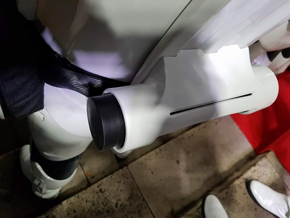
Yeah those should be hidden by the holster... I hope.1 point
-
You are clear to proceed (I’m guessing what appears to be burnmarks won’t be visible?)1 point
-
Great job on this, Jorge! I had recently been thinking about this build and wondered what the status was. Based on your previous batched posts I assumed you were making progress and would simply update us a later time... today! My TK build is progressing much slower. Haha. Sent from my iPhone using Tapatalk1 point
-
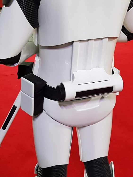
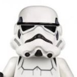
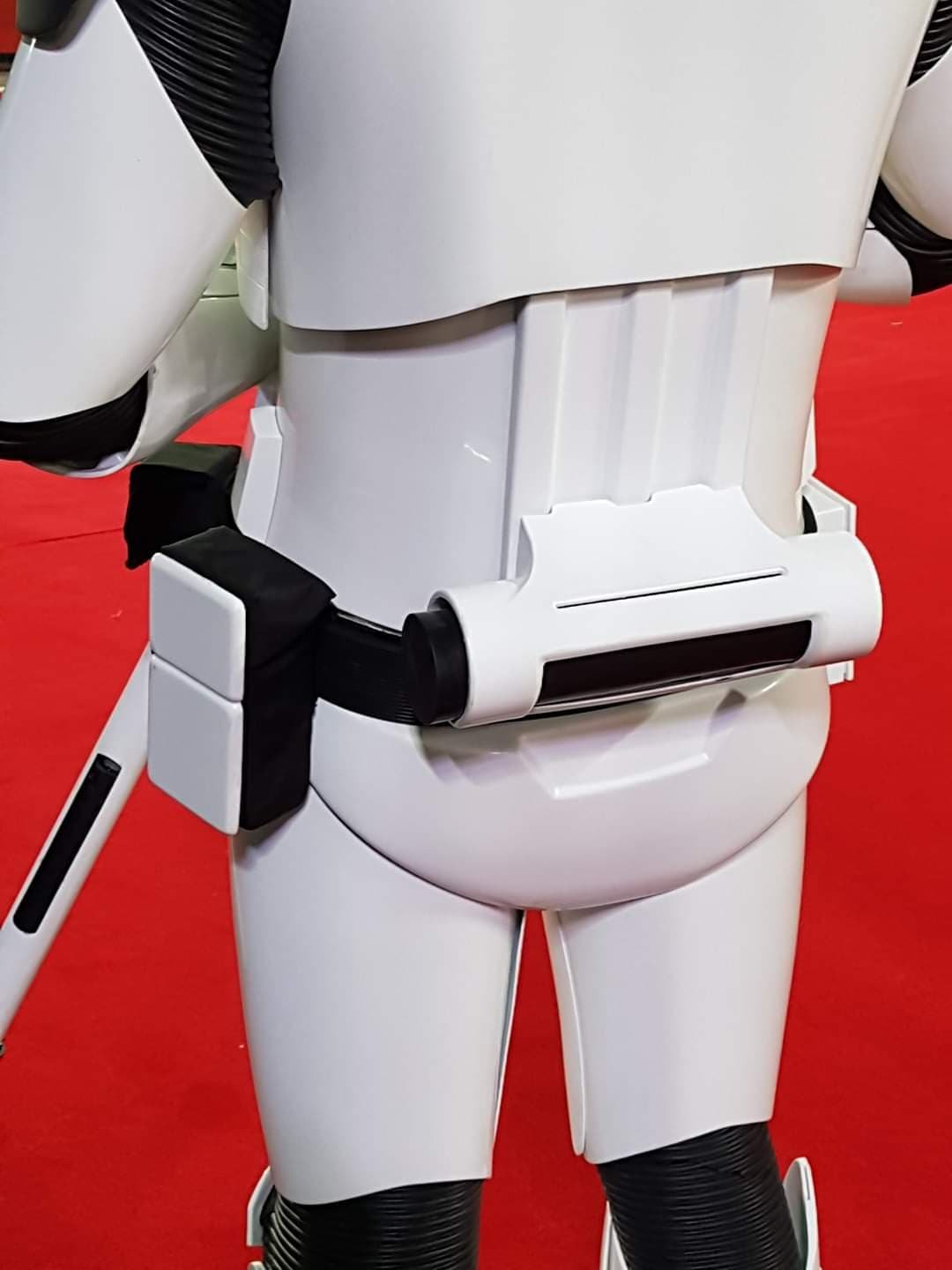
Is this about where the belt boxes need to go? They look good to me but I want another opinion before I glue them down.1 point
-
DOT (you find them on eBay) are marine grade snaps and an excellent choice as well1 point
-
Electronics are coming in. Ordering them from everywhere. Amazon, ebay, hobbyking... I have only a little idea of what I am doing. I have been reading as many build threads as I can find. Annoying some of the local droid builders and trying to make sense of all of this. I realize today, that I have turned into my parents with patience. I know am asking these younger droid builders to set the time on my VCR. Just testing for fit. I cut this plexi board to size. (I borrowed it from my wife's crafting closet, hopefully she wont need it ever) Controller...1 point
-
I put together the foot shells and I glued and assembled them, then I realized I shouldn't have assembled them until I install the drive motors so that was awesome! super tight squeeze! Hope those nut are on tight enough?! ugh, it took 2 days and having to go through lots of trial and error.1 point
-
Holy smokes! I have lots of updating to do!! Get ready for the mega dump! Here are a couple of leg pics. I need to go back through this thread. I noticed some or a lot of the images are gone. I am pretty sure when I was moving stuff around in imgur I didn't realize it would just remove the images completely. anyhoo...1 point
-
Latest fitting, with a few minor mods - V-tabs added - Thanks @gmrhodes13 for the advice - Calf closures completed - Thanks @Cricket for the tutorial and advice! - Back of thigh mobility trims - Cheers @Chemi - Forearms mobility trim - Internal strapping adjustment (Also misplaced an ear screw, so I purchased some: Brass Metric Flat Head Slotted Screws M3.5 x 0.6 x 30 from https://www.spaldingfasteners.co.uk/, which match the RS Prop Masters perfectly) No butt flare! Better alignment on the split rivets below What's left? - New Belt, as this one is too small, the velcro doesn't overlap. - Belt snap covers to be added - Paint the thigh split rivets - V-tabs on the far sides of the butt plates - Install the Aker comms - A general tidy up of any joins and I think I might be ready for submission.1 point
-
Haha I'm sure you're all good Fred- I'm finding there are many ways to go about assembling our armor kits. I've learned so much I'll likely buy another set of armor in the near future just so I can apply all the lessons and tricks I've picked up. I estimate I've spent around 100+ hours reading this forum and working on my own armor, so I wanna put all that time and developed skills to use again!1 point
-
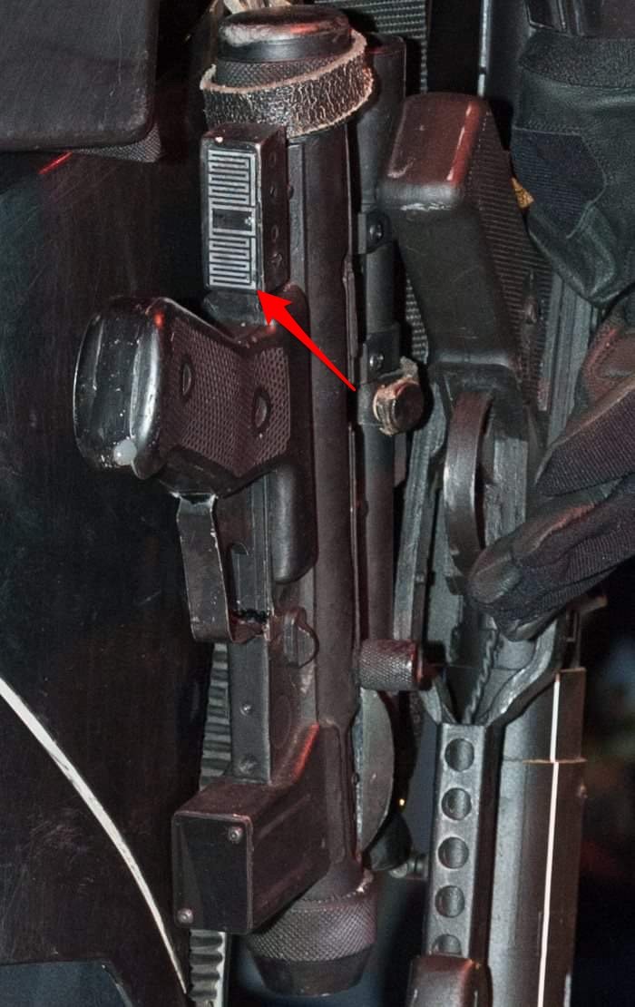
Couple of extra TD images from the Europeans Red Carpet of TLJ
 1 point
 -
Great job, Emma! That would have been scary for me too! Sent from my iPhone using Tapatalk1 point
-
Some one posted this thought thought I would share it again!! Lol Sent from my iPhone using Tapatalk1 point
-
Welcome aboard Fred.1 point
-
Very good Emma, very good ... Most of the hard work is done ...keep it up!!!1 point
-
I almost didn't do this tonight because I was so nervous, but I think I did okay (I am of course open to suggestions)! originally I was going to buy a pair of shorty thighs from WTF, but apparently there was the risk of them being a different shade of white, so I decided just to dive in and trim the ones I have. Be brave! First of all, a pic of the better-fitting gloves. Even though they ripped at the bottom , a new pair is on it's way! They will get here soon and then I'll install the hand guards. Even though the rip isn't visible I'd rather start with a fresh unripped pair of gloves. Time to assess the need for shimming the thighs again, wearing the proper under clothes! Yep, looks like a small shim will be needed for the thighs to slide on in a comfier way. As you can see, the thigh dips wayyyyy below my knee (and in the front they were jabbing up really high). I cannot walk! It was time to trim the thighs height-wise. Following the guide lines I drew above earlier, I marked on the thigh where I needed to cut it in order to have the bottom of the thigh sit just above my knee (and be able to bend it slightly- I knew I could cut out part of the back later once everything is glued, I believe these are called "mobility cuts"). I then drew the curves with a pencil along which I cut with my plastic cutting scissors. Here's a trimmed thigh versus an untrimmed thigh (height-wise). I measured the new height in the front and back of the shorter thigh and applied that to the untrimmed thigh to make sure the height on both was relatively equal. It will be impossible to tell for certain how things line up until I can get both on my body, but pure measurement of both says they're relatively equal. You can see height-wise they fit much better now. A little room in the knee. It's still hard to walk but that's where the mobility cuts will come in, and at least this time I can bend my leg at all to begin with! The way I'm holding it might make the thigh look a little too high up but I'm pretty confident I didn't overtrim- it still feels pretty long but I don't want to make any more cuts until I know how it will meet up with the cod and posterior. For now, I am pleased, and surprised that I could do it!1 point
-
I realized yesterday that I still hadn't attached the ab boxes on the ab piece. Time to bust out the E6000! Thankfully these two boxes have little grooves on the back so I could align them pretty much where they need to be. The larger middle box (not pictured) and the box to the right of it also have little grooves in the back of them for easy placement. The rest needed to be eyeballed on. I allowed a day for the E6000 to cure, and then it was time to paint. This part of the build is soooo flippin' satisfying. Two initial coats, and lookit that shiiine! As I proceed with the white gloss, I'm seeing areas that have very small flaws that I missed. And I can safely state that I'm finally at the "Good Enough" part of the build, so the small imperfections don't get to me now (you know what I mean... it's the stage when you don't care about itty bitty details enough to continue along with building). When I see something I overlooked (such as small pinhole in a Bondo'd area), I tell myself, "Battle damage!", and move along. I have really had enough of the fill/sand phase. My wire hangers arrived today (yay!), so I'll be able to hang and paint more parts in one session. If weather allows tomorrow, next up will be Round 2 of gloss white on the pieces I wet-sanded today.1 point
-
OP (MV) Post #25 FIRST BLOOD. A very minor cut, from a lexan scissor slip, and now that I've experienced this rite of passage, my build can officially commence. Ha. In today's update I will cover the following topics: Uncut belt and knee ammo pieces ATA vs. AP belt Rough cuts of belt and knee ammo pieces Additional trimming and sanding of drop boxes, shoulder bridges, and sniper knee plate Cover strip cutting E-6000 question Recent purchases (Trooperbay, Amazon, Lowes) Holster lubricant function The belt and knee ammo pack are the last two pieces of raw untrimmed armor which I have yet to present individually photographed, so here they are. They appear to be very crisp pulls and in the second series of images you'll see my ATA belt alongside an extra AP belt I purchased for my HWT build. Raw Uncut ATA Belt & Knee Pack AP vs. ATA Belt Rough Trimmed Belt and Knee Pack Today I finally trimmed the return edges off both the belt and knee ammo pack. After pondering what would be the best strategy to take, I opted for scoring the back corner edges at roughly a 45 degree angle. I decided on that 45 degree angle in order to keep some of the rounded (aka smooth) edges on the front side, but I may still need to trim more off each side once I measure; I know I'll need to shoot for around 3-5mm. The ATA belt has quite crisp lines, so there was a very distinct corner for which my blade to follow, and it only took less than five passes of my xacto blade to score most of the way through the ABS. Then some simply folding back and forth freed up the excess strip. Knee Ammo Pack I used the same technique for the knee pack, but first had to cut off the two short edges at either end. It only took two passes of my xacto blade to score nearly through the pastic, and in a couple areas I actually accidentally cut all the way through. Additionally trimming, with the rounded edges for example, will occur at a later time. I also did some additionally trimming on the drop boxes and the shoulder bridges, and tested some rough sanding. I tarted with 60 grit on the drop boxes and 120 on the shoulder bridges, and plan to later move up to 220, and maybe even 320 for a super smooth finish. Be sure to always wear proper PPE; this white plastic dust is no joke, and you definitely don't want it in your lungs. Quick technique note: cutting off the corners of the drop boxes made it easier to get to those straight runs. Just be careful not to take off too much in the corners at the beginning. I'm shooting for 15mm deep outer boxes, and flush inner boxes (likely around 12mm). Finally, as far as trimming is concerned, I did a little more scissoring on my sniper plate, and I think brought it a lot closer to the final profile. Mainly I was concentrating on the curve/angle up to the raised section, as I know I'll still need to cut the back corner edges and the bottom return. Does the side profile look ok, or should I make the curve a more distinct angle? Concerning Cover (finish) Strips I finally cut my first cover strips and here are the resources and technique that I put to use. I figure I would document my steps since they are sometimes overlooked in other builds, and I only did the two front thigh pieces, and opted for a 20mm width. Terrell from ATA writes 7/8 inches (22.23mm) as the measurement on the spare ABS sheets included with the armor, but that is simply a rounded imperial figure, and I want to avoid any imperial entanglements. To account for potential improper blade angle and sanding, I added 1mm to my measurements, so my cut marks were drawn at 21mm. Provided that fitment allows it, my plan is to utilize 15mm cover strips on the fronts and back of all arm pieces, 20mm on the thigh front and backs, 20mm on the shin front, and 25mm on the back calves. These are shown visually in the two graphics below, which I borrowed and adapted from ukswrath's ANOVOS build. Here are resources I found helpful regarding the sizing and cutting of cover strips. The build thread links below are for posts in which cover strip cutting techniques are described with photo illustrations. Forum discussion threads for dimensions reference (by year): 2011 | 2013 | 2014 | 2015 | 2017 Build thread references: Ukswrath (pages 1-2) | A.J. Hamler (#1, #2, #3) | Cricket | StrmTRPR85 | wook1138 | LEGOeatPokemon/justjoseph63 | dereferenced (#1, #2) | LadyInWhite's Google Doc As far as my technique is concerned, first I measured (thrice) and marked the cut lines with a pencil and then I clamped the ABS sheet nice (outer) side facing down onto my cutting mat and desk, with a metal ruler on top. I cut my score lines into the back of the sheet in case my blade slipped, therefore leaving any potential stray cuts on the back of the cover strips. I did not want to cut all the way through the plastic, so instead used the score and snap method. I used a metal ruler WITHOUT cork backing in order the keep the metal guide as low to the ABS as possible, thereby increasing my chance of cutting a perfect perpendicular line into the ABS. 5-7 runs with the xacto knife did the trick, then it was on to folding and snapping the piece. During my first attempt (shown above) my cut line was under the clamp arms, which complicated things, so for the second strip (shown below) I flipped my ABS sheet around so the cut line was unobstructed. The resulting cut on the back of the sheet, perhaps about halfway through the ABS. I then re-positioned the entire piece with the ruler situated right on top of the newly-scored strip. I then leveraged the entire remainder of the sheet, bending it downward off the edge of my table. Once I had a solid fold line along the entire length of the sheet I bent the strip back and forth multiple times before it eventually snapped off on its own. No additional use of a blade was required, nor would I suggest it, to avoid any stray cuts (likely with very sharp blades). Immediately after cutting the strips I labeled the front/back with masking tape to ensure I glue the correct sides when that time comes, and below is my finished product. The cuts are perfectly straight, and I'm very happy with my product. Sanding will wait until later. Quick question regarding E-6000 and armor forming. I understand that E-6000 can maintain adhesion in boiling water baths, but is there a limit to the amount of time it should remain underwater? I'm anticipating needing to form my arm pieces after I've glued them together, but I will hopefully I'll have gotten it close prior to gluing with water baths using rubber bands or zip-ties. Thoughts? I'm hoping to have finally purchased the last several tools that I'll be needing for my build construction this week, but I do still need several components/accessories such as my TD belt clips from @ukswrath. Tony - I believe your hovi tip screen mesh is more accurate than that provided by ATA, shown in my previous post, correct? I also still need to order my canvas belt from Rob Kittell, but I don't yet have an armor-on waist circumference measurement yet, so that will need to wait a little while longer. Items recently received (shown below): Dritz 9334W 3/4-inch white braided elastic from Amazon, for drop boxes Blue Hawk chemical gloves, for hot water armor baths, from Lowes Buckle straps for thigh garter waist and HWT pack from Amazon Novus 7100 plastic polish kit - 8oz, from Amazon Items on order: Humbrol Mediterranean, Midnight, and Sea gloss blue paint from Trooperbay. I couldn't resist by try them all. I STILL CANNOT LOCATE ANY FRENCH BLUE. Will one of these aforementioned options suffice, or does anybody have a US purchase source, preferably online? Humbrol Admiral Grey #5 to go along with my Testors 1138. Any preferences to one or the other? Tube stripe and tear masking templates from Trooperbay, hand-painted style Screw thread protectors from the screws inside my helmet, from Amazon Craft foam for cutout around my frown screen mesh Cotton fabric by the yard for magnet sachets Sugru form justjoseph63 To briefly follow up on my holster lubricant application. I gave the inside of my 8oz leather Darman holster several sprays, and my rubber E-11 really does slide in and out of it more easily. It seems the final catch points mentioned in my previous point are now slick enough, and hopefully no additional weathering will get rubbed off. Finally, in case any of you are wondering why my build progress is always so slow, it's because I'm limited to only doing my research or construction between midnight and 3:00am, or 5:00am-7:00am. This build is currently my own side-project, rather than an entire household endeavor, so basically family (wife and baby) time come first. TTFN1 point
-
Joined the two pieces of my left thigh yesterday. Both thighs have now been trimmed and joined at the front via an inner strip. USPS still hasn't provided an ETA for my incoming extra ABS material, so I'll probably apply the outer cover strips to my thighs today and move onto other pieces. Next up: water bath shins and biceps again, then I'll do some final trimming on the tops of my biceps and inner forearm elbows (so I can fully bend my arm).1 point
-
As you probably have read in the crl : The drop boxes dangle from the sides of the front plastic belt (ammo belt) via white straps and are aligned under the plastic tabs of the ammo belt. There's no specific material for the drop boxes connection to the Belt. I have seen both , Elastic and webbing. More accuracy? Elastic . looking for more firm connection? webbing. for higher levels you must consider the following. Drop boxes are vertically aligned with the end of the ammo belt with minimal gap between belt and box in my opinion webbing give more firmness to the alignment , in exchange the elastic stretches over time and may cause the gap to increase Cheers1 point
-
Eric Foehner 37423 Centurion letter Sha Sha http://www.whitearmor.net/eib/certificates/37423-centurion.png1 point
-
Thats more or less how I've been joining the parts, then going back and "welding" them with a soldering iron and filament filler. Sadly this went at a weak spot. It was a very early print and I've changed a lot of how I print since, so I plan to reprint. That said I will repair this too so who knows, I need to fibre glass some bits anyway and maybe that will save this part?1 point


.thumb.jpg.77bd551337f7adc46a4b151e703df6be.jpg)