Leaderboard


Popular Content
Showing content with the highest reputation on 02/04/2018 in Posts
-
Just as an FYI, given that we are in election period, and given that we already have had issues with the forum software, we'll not be touching *anything* until the election cycle is over on the forum site. We'll take a look once again once we are past that cycle.2 points
-
Need to get some more for when I do the scope...only got 16 and 22mm in my drill set [emoji20]. Well..,,that wasn’t easy! Took some hollowing! Trimmed the false bolts from the end of the stock, drilled for the replacements, hollowed the body out, drilled through the butt part and put a groove around it to give the impression it’s a separate part. Just need to make a hinge for the back end. Sent from my iPhone using Tapatalk2 points
-
Thank you so much for that and the time spent reviewing my application! I’m over the moon!!!!!!! Big shout out and thanks to Fabrice Jouglas for his unwavering support and expert advice! Salute! Alban Sent from my iPhone using Tapatalk2 points
-
If Only I Had Known Read Ukswrath’s thread all the way through before you begin. It is filled with tidbits that you will want to know ahead of time. There’s plenty to read until BBD. Get more magnets and clamps. I got 20 thin ones; 20 thick ones would have been better. Read the Centurion approval threads. Learn from other people’s errors. Oopses Peel the protective film off before you glue things together. (Don’t worry: It peels off. Then you can reglue the parts.) If it doesn’t feel like it fits that way, then maybe it doesn’t fit that way! Fo your approval photos, get someone to help. The TK Armor is not easy to put on yourself and get right for inspection. Additional Advice The Anovos strapping system is okay for initial fitting and your submission photos. But you will probably want to upgrade that. The Anovos belt is silly. Get a good one like Imperial Issue. Get Centurion-approved boots even if you don’t now plan on that level. The Sterilite 32 gallon tote is perfect and is a good thing to practice masking and spray-painting on. Thanks To The fine troopers in FISD who encouraged and advised me along the way. My friend Razek the Dragon who took time off from his vacation to help me suit up and pay attention to and fix all those finicky details. He earns a 501st patch!1 point
-
My belt snaps didnt work out, they werent aligned quite right. Didnt bother swapping them out, just added some velcro and its still holding up after a year of trooping. Sent from my SM-G935V using Tapatalk1 point
-
Congrats ! Welcome to the shiny white1 point
-
I am the Master Builder for the OC Squad of Southern California...I've probably helped 20 or so people with their builds in the last 2 years or so....I will never have the time to research through all this...Erik Duane, Jesse Terrazas, Kelvin Pham were 3 EIBs that come to mind...I don't keep track but I know there are many more in there somewhere...1 point
-
BTW nice onesie1 point
-
To be more clear, the CRL says *nothing* about the presence of the U fabric on the sides, e.g. doesn't say that it cannot be present. The prototype as shown complies with the CRL as I read it. Heck, in comics they leave out the U too, so I don't see a material difference. Here is a pix from last Celebration. Check out the boots.1 point
-
For level two certification (if applicable): Folding stock (does not need to function). A real or replica ammo counter - based off of a Hengstler counter - shall be present. D-ring mounted on the rear. Sterling based blasters have the correct M-38 or M-19 style scope. Two power cylinders on the magazine housing. Scratch-built or cast blasters shall have a total of 6 T-tracks on blaster (leaving the lowest row on the magazine housing side uncovered). If using the Hasbro E11 toy blaster, it is modified to have the correct number of T-tracks (6 total), with a lower row of open vent holes on the magazine housing side. This is accomplished by covering the pre-existing rows of holes with T-tracks, then grinding off the lower integrated T-track on the magazine housing side, and drilling a new row of holes in its place. No ESB/ROTJ greeblies are allowed on the blaster. For level three certification (if applicable): Hasbro blasters are not allowed, even conversions.1 point
-
As a GML, I'd let these pass in my garrison. As DL, I would recommend a GML let them pass. Ultimately it's up to your local GML.1 point
-
Last few things and I’m ready to suit up for the first time. And then the tweaking and upgrading. Anyway, before all that... Installing the dark green lens from trooperbay. By the way, he has a great video on YouTube for this. Fit to the ear screws- I used the top two screws I each side - and drill holes and cut away part for nose. I sanded the edges and polished the whole lens. Added s-trim. Wow, that was harder than I expected. I read some place to cut the piece about an inch too long and cram it into place to hold it together better. This is what I did. I didn’t glue it, so we’ll see how it holds up Done Sent from my iPhone using Tapatalk1 point
-
thanks! You were a huge help Daniel!1 point
-
Spade bits and vacuum cleaner at the ready.1 point
-
Maybe apply green stuff to your cut out sight block and shape to desired?1 point
-
Great work, Wayne. Re the front sight, you could pad that out with green stuff if you wanted. Whilst mine is far from perfect, I added green stuff to mine, then sanded it to the shape and size required. :-)1 point
-
Thanks Jesse...very kind of u. I’m thinking I might have to make a new sight block from scratch. The resin one looks too small for me to get a symmetrical finish to it? What do u guys think? Sent from my iPhone using Tapatalk1 point
-
Like Glen, I used snaps for all connections. After a few years of Trooping and sitting in hot armor bins, elastic can (and will) stretch and wear out. (I have had this happen). When gluing the bottom (flat) part of your snap to the armor, use nylon and E-6000. That way, you can replace the top part of the snap that is attached to the elastic if needed. BUT... be SURE to use the exact same brand of snaps that you did originally, as the size can vary slightly among mfrs.1 point
-
Hi Dan, I made some adjustments to the arms and reduced the wrist/ forearm /elbow/ bicep gap. I updated the photos to show this and I think it looks much better. matt1 point
-
Thank you very much Tom. At least that explains the recent messages in my inbox.1 point
-
Hehe - of course, I only jest. Your kit is incredibly comprehensive and doesn’t really need additions. As you say, a straw or many other small, pole like objects would do the trick. However, as you’ve probably guessed, I have easy access to lots of Lego and play-doh! (Thank you, children) Hehe1 point
-
If it makes you feel any better YOU will be the only one who notices. I destroyed my belt rivet caps while I was replacing the canvas portion of the belt on my Anovos kit, and had to source replacements from ATA - they’re just a hair off from Anovos’ shade of white, but if I try to point it out to other people they act like I’m insane.1 point
-
No worries, Dan. What you did, is just the best and simplest way to install the small lens from the outside of a scope. Everything else is a lot more effort. Posted two photos in Mark's (Suspend) thread to help. Hm, instead of using LEGO, the same can be done with a drinking straw or something similar. But I guess people would wonder about finding such an item in a completion set. Also, I am trying to not add even more items, as it is quite a challenge to always have every single piece (67 in total) available for shipping a set...1 point
-
You might want to look into EL panels. This will look amazing if you can pull it off!1 point
-
Hi Mark, you asked the question below in a different thread so I just wanted to help. But instead of posting it there, I thought it might make more sense to reply here instead. That photo shows how to dismantle the other half of the monocular and get a total of two small lenses, both in same size and suitable for our resin scopes. And here is one option, how such a lens can be installed during the build. Of course you can also just add it from the outside by using a Lego flagpole, play-doh and superglue. Very glad, that Dan (CableGuy) had covered you so fast.1 point
-
Good job, Alban. Another great looking trooper added to the EIB ranks.1 point
-
Let’s hope there’s no return of the money. Followed by the debt awakens and the last penny.1 point
-
Armor maker doesn't matter, construction method does... though the closer the match the better obviously. You should be fine.1 point
-
I spent some time working on the bucket today. Here I am getting everything masked off in preparation of interior coating. I applied three liberal coats of bed liner spray. Fitting the lenses as one piece. I will bolt these in with the side bucket bolts. Bucket bolted together and ready to trim the ears. Cheers! Sent from my iPhone using Tapatalk1 point
-
Very cool Jim1 point
-
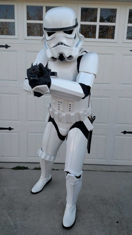
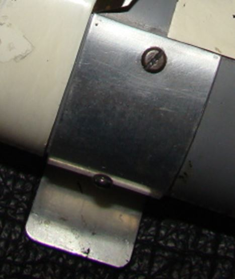
G'day Alban thank you for your EIB application and your patience as we catch up, so let's have a look. CRL and EIB Application Requirements: All the required submission photos have been posted, and your armour meets all the necessary requirements for level 2. With that Tony and myself would like to welcome you to Expert Infantry, congratulations Other-Armor Fit/Assembly: In this section we review observations made by your fellow troopers and ourselves. Some observations may lead to suggestions to improve the overall look of your armor. If any suggestion affects any application, it will be listed separately in the above or below sections. We can see your a stocky guy and you have done a great job to get this armour to fit. We do have some minor things that are simply dressing issues, so some adjustments, a mirror and an assistant will get you looking in the best shape you can. In the below image I have highlighted the areas and will give some explanations as how things should sit and look. I will add the reference images below your images. Shoulder Bells: the tops of these should virtually, if not touch the plastic shoulder bridges. Perhaps shortening the top connecting straps will bring them in. It will also reduce the gap between the front of the bells and the chest plate Fore arm position: The forearm outer cover strip, needs to line up with the bicep center cover strip , this will bring the scalloped out section to the inner bend of the elbow or facing your fore arm. In turn the dimples on the back of the forearms will now face out instead of to the back of the arms. Thigh position: your thighs are sitting to low as mentioned by one of your fellow troopers. these can come up an inch or so and will stop the bottoms from sitting directly on top of your shins. Should also give you a bit more flexibility to bend the knee Shin rotation: one last adjustment from the front, would be to rotate the sniper shin outwards so the cover strips line up with the thigh cover strip. That shin is also sitting higher and should come down to the same level as the other. Shoulder bell reference image Fore arm position reference As we move around to the back there are a 3 things that can easily be remedied so lets look at those. Gap between Back and Kidney plate: When looking at your internal strapping, i think we can see why you are getting the separation. Replacing those 2 narrow elastic straps with some wider elastic and also moving those outwards a little will give you the added strength and less stretch hopefully stopping the gap occurring. If you can get them sitting on top of each other, that would be perfect. Butt plate popping out: Moving the outer 2 elastic straps closer to the ends and again, using wider elastic will also reduce the amount it will pop out at the end. Rear cover strip sizing: The shin cover strips should be virtually the same width as the rear thigh cover strips. Not sure why you needed to make both of them so wide as the thighs look to fit well, but the shin strips do look way too big. Ear screws: The top two screws look to be correct, the bottom screw is a dome head rather than the above flt blade tapered head. this one will need to be replaced. Thermal Detonator screws: This is one of those nice to have things that we like to see for a Centurion application. The correct type of screws to use are flat blade pan head variety, and they should be painted black for that ultimate look. Reference Image. Centurion Suggestions: In this section we prepare you for Centurion. More photos are requested that allow us to make better decisions on possible adjustment etc. If there are any areas of concern they will be discussed here. Great work on those side shims Alban, all you need to do to get them Centurion level is to only have one seam on each side. Filling that second seam with ABS paste is the way to go about it. There are a few examples and threads here on the forums. As stated in the CRL for level 3 For level three certification: A single visible seam line is present. Drop Box alignment: It looks as though your drop boxes may slide around a little from some of your images. These need to sit inline with the very ends on the plastic ammo belt For level three certification (if applicable): Drop boxes are vertically aligned with the end of the ammo belt with minimal gap between belt and box. A small dab of glue or even adhesive Velcro will keep these from moving inwards, so they always sit in the perfect spot. Reference image That is it my friend, Congratulation on your EI award, make your adjustments and modification, follow the Centurion photo check list and we hope to see an Centurion application from you in the future great job trooper1 point
-
FYI we gave the data to the Legion web team who are still working on it. They said it will be done before voting opens.1 point
-
Question #1 not sure Question #2 His name is Walt. But they quickly reply on their Facebook page. Also ATA is an option for replacement parts. Both Vendors info can be found in the Getting Started section in the vetted armor maker thread. Question#3 I'll just say, don't be a Rebel Dottie[emoji12][emoji3] Sent from my LGMS631 using Tapatalk1 point
-
Yep, trim the top part first and then work your way down front and then back (alternating). Can send pics if you need them. Lou1 point
-
Congratulations on your first of many to come!1 point
-
Wow - that’s a great list of positive events, Jim. Happy belated birthday, and well done for the troop and Aker wins.1 point
-
Hmmm.... 22:10 GMT and I can now “like” things again. Same day, within 24hrs. I’ll report back if this problem occurs again. Dan1 point
-
okay, made my first walking parade today ( about a mile and a half) This accomplished two milestones: 1) longest walk in full armor, and 2) longest walk since having my hip replacement implant 11 months ago Additionally, I finally was able to control my Aker feedback issue and more than doubled my sound volume! This involved not only some minor burst/echo/static sliders adjustment but the major problem solver was mounting a thick strip pf memory foam above the Aker box just below the neckline on the chest plate. This really blocked out the sound from feeding back up into my helmet that was causing the feedback loop. Absolutely no squawks for about 3 hours of use, I'll call this a major win, and of course the magic volume mark has been "silver sharpied" Another added bonus is that with my birthday just passing , I'm going to apply some of the gift funds to a better and approvable blaster ....more to come1 point
-
First Troop! At a SC Stingrays Hockey game, with jersey auction/raffle proceeds going to Charleston Habitat for Humanity. What a blast. We got to accompany the ceremonial Puck drop, and walk the mezzanine. Crazy seeing people from work, and the public, and their general reactions to the armor. Loved every minute of it. Aside from a couple of armor bites on the calves, it trooped perfectly. Sent from my XT1254 using Tapatalk1 point
-
I contacted TG yesterday and he replied with this shoulder Bell confirmation. ... “The one in the picture on the left goes on the right shoulder. They swoop back, if that makes sense.” So tonight I finished the taper cuts on biceps and forearms. I’m really with the fit. I am going to get arms and legs ready for covers strips, then do strips all at once. I decided to get started on the 4.5 bucket next. Here you see the teeth cut out. This is going to be a really easy helmet build. The eyes came pre cut from TG. Ear bases trimmed and brow rubber installed. I am still trying to decide if I want a low or mid brow for this bucket. This pic shows a mocked up mid brow vs. my low brow WTF bucket. I am leaning towards mid to give me a little more room for interior padding. That’s all for tonight.......cheers! Sent from my iPhone using Tapatalk1 point
-
EIB submitted fingers crossed1 point
-
Hi all, Wish me the best! I will be attempting to scratch build the magazine to fit into the doopydoos magazine housing. I contemplated on how to modify my existing doopydoos magazine but the scale and detail just aren't there, so not worth the task. I've relied heavily on templates created by FISD mates Lucas (ZeroRoom) and also Rob (Ducati) for the larger side plates. The clip latch took some time to figure out a template from these guides, but I managed to do so. When putting up my assembled template side by side with Steve (Gazmosis) resin magazine (no longer available on FISD), I feel confident I've captured the essence of it. As for materials, I will likely go with styrene plastic and have a go at the 'score-n-snap' method and see how I make due with bending plastic using an iron. Check out how I progressed to get my final assembled template ... Preliminary attempts at replicating magazine with aluminum sheets, yes of all materials, I chose aluminum. Doopydoos magazine placed for comparison Paper template construction of magazine following ZeroRoom SMG templates on FISD versus doopydoos magazine Ducati template blueprint showing dimensions against an SMG reference Ducati template of magazine cap Ducati perspective view of template components Upgraded paper template magazine with Ducati templates; replaced larger side plates and cut to desired length Quiet happy with the templated magazine latch After studying SMG references, I know now that the corners on the latch and on the rear of the magazine is to be positioned up against the entrance to the magazine well Final paper template construction of magazine with magazine latch and also compared to Gazmosis solid resin piece from FISD I've got goose bumps ahead of starting, but with allot of forethought and a little detailed work, really want to see it realized. Cheers all! have a terrific weekend!1 point
-
Looks good to me, definitely appears overlapped.1 point
-
I have a question about the inner seam on the biceps. For level 3 cert it says that the seam need to overlap. I’m not necessarily going to lvl 3 but since I’m doing executioner as well I figured I might as well overlap for these pieces since they clearly do on the executioner. Here’s what I have so far on one bicep. Thoughts? Would this be okay for both TFA and Executioner?1 point
-
Paul, can we chat regarding Vincent's design? To keep costs down and remove some of the issues with the flap, I asked Vincent to produce a prototype with stitching that would emulate that look but not have the issues associated with the flap (the adhesive comes off, color differences, fraying and damage from the shin). These are based off the original boots that were approved as the original CRL (before Gio's photos were added to the CRL). Here are photos of the prototype: Would really like to have a reliable vendor like Vincent on this project... hoping this can help our new members and the ladies that have worn-out originals!1 point
-
Sorry for the delay. I guess for me as a GML when there are very hard to find items like this, I take the approach of if it looks right, flies right. There is a bit of a front flap detail and if you have the lower leg armor over it, it may end up looking the same. Some GMLs may be very hard line about this, so it will depend on your local GML.1 point
-
FYI, the sniper knee rivet has been fixed in the CRLs.1 point
-
After a far away troop today, I'm back and plugging along with a few more things tonight. Adhesive: At the recommendation of others, my principle adhesive will be ABS cement. I found this on Amazon (adding link to OP). I probably got waaaay too much but better than not enough. Never having purchased it before, I wasn't sure how much I would truly need. You'd probably be okay with just a pint for this build. It says "Low VOC" but it is really smelly! With small kids and a pregnant wife in the home, all glueing will take place in the garage with this ventilator. Fixing Imperfections with Heat Gun Some of my pieces have some "bubbles" or lips that make good edges more difficult. I decided to attempt some heat gun work on one such flaw on a piece of bicep tonight. My gun has a "High" and "Low" setting so I set it to "Low" hit the area for no more than 7-10 seconds at a time and pressed it against a flat surface to flatten it out a bit. Before: After: Biceps Pt 1: Content with that small fix, I then proceeded to glue one side of the biceps tonight. To do so I glued an interior cover strip to each bicep like so... After letting that cure for an hour or so (way better turn around time than E6000) I then glued the other half to each side. There are small gaps near the top and bottom of the seam but that will be filled in and painted over later one so I'm not concerned about them. Shoulder Bells: I also worked on the shoulder bells tonight. Following Ruthar's great tutorial, I clamped the inserts so that they stick out from the top edge of the bell about 1/2". I then traced the outline of the insert with pencil. Finally, after sanding the insert and the outlined section of the bell, I applied adhesive and clamped it down. I repeated these steps for the other bell. Executioner Bells: I then repeated the above steps for the Executioner Bells. They will be chillin' for a while until I get to painting them. Posterior Prep for Strapping: I also took the opportunity while things were drying to prepare the posterior piece for future strapping. I measure the length of the notch and split the difference. I then created faux notches to match the Anovos piece at 50 mm distance from that center line. Matching the distances outline in Ukswrath's thread of 3/4" in and 1" up I marked some holes for drilling. I'm not sure if it had to be exactly those distances and such. The key is symmetry and consistency. The little "swoop" up on the top center ridge was how the piece came to me so I just had to deal with it like that.1 point
-
Hey Everyone, Andrew here. I was just approved and can't wait for my first troop. Submitting my EIB application presently. Cheers!
 1 point
 -
Hi Daniel welcome to your EI review and thank you for your application. CRL and EIB Application Requirements: All submission photos have been posted. Your armor displays all the necessary elements to qualify for Expert Infantry. Welcome trooper, congratulations! Other-Armor Fit/Assembly: In this section we review observations made by your fellow troopers and ourselves. Some observations may lead to suggestions to improve the overall look of your armor. If any suggestion affects any application, it will be listed separately in the above or below sections. Very nice build, excellent work Dan,good attention to detail and great looking E11 as well. We only have a few small items to mention so here they are. The first is simply a dressing issue, just get the gap between the bottom of your bicep and top of the fore arm even on both arms. The second is a very quick trim job on the cover strips on the back of your thighs. These look like they could cause you injury potentially damage your under suit. I would sand those pointy corners off as a preventative measure. This last one is just an accuracy thing, a nice to have but not a necessity. You have slotted screw and yes they are painted black, but the screen used screws are the pan head variety, not the dome.Like we said, not a necessity but another step closer to screen accurate. The reference image shows what a pan head screw looks. Centurion Suggestions: In this section we prepare you for Centurion. If there are any areas of concern this is where they are discussed. You have provided a pretty comprehensive set of images so this makes it easier to see if anything we cant normally see might stand out, and we are happy to report everything is looking good for an easy Centurion application. Congrats once again and hope to see you in Centurion review soon.
 1 point


.thumb.webp.27f7939d37871f319ff836257d4a3668.webp)