Leaderboard

Popular Content
Showing content with the highest reputation on 02/17/2022 in all areas
-
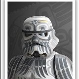
I recently completed a build of a 3D printed ANH E-11 which I modeled and printed myself. I used PETG filament and printed all the parts on my Creality CR-10S printer. I picked up some good pointers from justjoseph63 and his excellent tutorial on smoothing a 3D print: PETG is a wonderful material and sands beautifully. Yeah, it was a lot of work, but not as hard as you might think. I printed my parts a standard resolution (0.2mm/layer) which is already fairly smooth. I sanded with 100 grit followed by 220 grit. I used putty to fill in any blemishes or scars left from support attachments and sanded again with 220 grit. Instead of using the XTC-3D epoxy in the tutorial, I used multiple coats of Rustoleum Crystal Clear spray enamel, which I sanded to a very smooth finish. For the topcoat, I used Rustoleum 2X flat black on the sterling barrel and frame/end cap. I used Rustoleum 2X matte black on the scope, Hengstler, and grip. I also sprayed the grip with clear coat to give it a glossy finish. I painted the fire control group housing and bolt with Testors steel enamel and used a flat black acrylic paint and water mixture to tone down the steel color and add dimension. I used a formed metal spring instead of the printed spring. I highly recommend doing this. I did a bit of light weathering on the finish. I used acrylic silver to touch the edges of the Sterling and dry brushed sparingly on some of the flat surfaces. I blackwashed over this and used a paper towel to get the finish I wanted. On the scope, I touched up the edges with acrylic antique gold and used a white crayon to fill the text on the eyepiece. On the Hengstler, I painted the logo window acrylic antique gold and blackwashed over that until it was nearly hidden. I also painted the number display. Functional features of the blaster include: MOVING/RESETTING TRIGGER INDEXING THREE POSITION SELECTOR SWITCH REMOVABLE END CAP FUNCTIONAL END CAP RELEASE RECIPROCATING BOLT FUNCTIONAL MAGAZINE RELEASE REMOVABLE MAGAZINE FUNCTIONAL FOLDING STOCK REAR SIGHT FLIPS BETWEEN 100M AND 200M APERTURES GRIP, FIRE CONTROL GROUP, BOLT, AND CHARGING HANDLE ASSEMBLES/DISASSEMBLES LIKE A REAL STERLING SMG MARK IV (L2A3) 1942 M38 HOLLOW SCOPE WITH CLEAR LENSES HOLLOW HENGSTLER WITH FUNCTIONAL RESET BUTTON Here are a few photos of the finished blaster! If you want to print this blaster yourself, click on the links below for the FREE STL files: https://www.thingiverse.com/thing:4003566 https://www.thingiverse.com/thing:3989097 https://www.thingiverse.com/thing:5139600 If you would like this blaster, but have no way to have one printed, check the Ongoing Sales and Project Runs section on this forum. From time to time, I will make a limited run of blasters and post there. https://www.whitearmor.net/forum/forum/16-ongoing-sales-project-runs/2 points
-
This is BEAUTIFUL!!! I'm blown away at how nicely it came out. Side note: to download an entire thingiverse fileset, remember to add /zip to the end of the URL. This prevents you from being forced to watch the 5-15 second ad for EVERY. single. downloadable file. Thingiverse has declared war on their users in the past couple weeks.1 point
-
Thanks Tino! This was definitely a labour of love. The printing was typical filament layers and took quite a bit of sanding. I now have to make a stand or display mount for it. This summer I will try building a blaster weapon rack, similar to the one seen in the Death Star Security office, so it can be displayed beside my armor.1 point
-
Dang. Being an old-school resin blaster builder, I always stayed away from 3D-prints. Seems like time has come to re-think this point of view... I really like this blaster.1 point
-
AMAZING JOB!!!! I haven't seen this one in person yet!1 point
-
Always impressed with your work on these incredible files and final products! Amazing work, and a fantastic resource for troopers. Sent from my iPhone using Tapatalk1 point
-
Hola, Gracias por el recibimiento. Si deseas hacer trade de parches o stickers personales avísame. Tengo parches personales de mis trajes de TK, SL, TX y DZ. Podemos coordinarnos por Facebook si deseas. Buscame como KEREM SOYYO.1 point
-
Hi. I did the request. Thank you. Greatings from Mexico1 point
-
Hello and welcome aboard trooper. You can request higher access here Hola y bienvenido a bordo soldado. Puede solicitar acceso superior aquí1 point
-
1 point
-
At long last it is done!!!! I finally managed to grab some pics and videos of the final build. Youtube link to 4 videos will be posted at the bottom of this post (hopefully it works...). One of the videos has my commentary. Other ones are just showing the blaster and me pew-pewing with it, as well as the lighting effects of the barrel in a darkened room. Please bare in mind I am not a photographer or videographer, so be kind. I touched up some of the paint from doing the final build steps. I then clear coated everything in a Sem-gloss paint from a rattle can. This ended up being to shiny, so I went over everything again with Tamiya model paint dull coat. Everything except the shiny rings between the butt and receiver, and the butt itself. Enjoy... Over all shot. As you can tell, I am using the gun vise and not using the blaster bi-pod to support it. I still don't trust the bipod due to the cracking issues I had before. Each leg seems to flex when I tried to rest the blaster on them. Loving that side box paint job! My scratch built display details, as well as the fully functioning fire selector switch. Main and scope displays in the modes that I like, as viewed by a gunner. There are several different options for each display. Details of the bottom barrel T-track wires and pigtails. Of course, once all this was done I then found a new to me screen grab pic that of course shows the wires not at the end of the t-tracks, but more away from the edges. You can see the barrel wiring through one of the holes. Small sticky sided velcro strips that are required to hold the bipod up in retracted position. They can't be seen when the bipod is swung up. Velcro on the "Bipod Hold open knubbly conical bolt device". That is my official name for it... Underside of the receiver. The opening is where the main display would normally be. Not very useful or ergonomic for a DLT gunner checking on his ammo count... That is why I made my own. This is a separate panel that you can replace with another provided panel with no holes in case you aren't installing a Blast-FX. Just forward of the opening you see the sliding ON / OFF switch for main power. Forward of this is the button that you press momentarily to cycle fire modes (as opposed to using the grip circular switch). Or you can hold it down to enter the Blast-FX set-up mode, that, in conjunction with the trigger, allows you to change sound and lighting options. The main circuit board memory stick of the system has sounds for most weapons used in the SW universe, as well as ship sounds! It is funny having a blaster that emits the sound of a TIE fighter or the Millennium Falcon each time you press the trigger. LOL Internal wiring and battery compartment with the receiver cover lifted up. You can see my resin 3D printed cocking handle. The screw did not come out when I started unscrewing the handle for transport. One last thing to fix. Video Link: I made a playlist with 4 videos. Maybe was a mistake? Anywhoooooo, if you click on the link all 4 will play back to back. Just fast forward them. sorry. My longer video with commentary is the last one. One or two of my pups show their faces1 point
-
Welcome!1 point
-
Bienvenido a bordo Darth Pakal!1 point
-
A bit more work done. Tubing installed in the blaster. T-Tracks from Wannawanga trimmed and installed. I just used the DLT Blaster images and tried to replicate the correct angle and small groove the wire sits in: Original and trimmed length. Wire I am using for the t-tracks. It is "Lock-wire" used on Jet airplane engines to prevent bolts from loosening. Being a former aircraft technician and learning skills like lockwiring has it's perks... It's even a suitable dark grey colour that won't need to be painted. T-tracks glued on with E-6000. Lockwire is then tightly wrapped and secured using what we call a pig-tail twist. This was trimmed then tucked away out of sight on the bottom of the barrel shroud. Front and rear barrel sections with everything installed. It was at this point I remembered I had to replace the barrel locking lever piece that fits in this groove below the circle. I lost it at some point during my move across country... You can also see the laser poking out of the side box (bass piece.) I just painted the outside of it black. Scrap plastic cut and trimmed and sanded to fit. Installed but not glued in yet. The front portion (towards left of picture) has been trimmed and rounded slightly to match reference pics. I also cut some grooves at the front that provide grippy texture. That's it for now!1 point
-
Received approval from my GML today! WOOT, finally!1 point