Leaderboard


Popular Content
Showing content with the highest reputation on 11/14/2021 in all areas
-
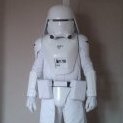
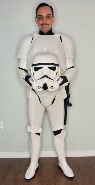
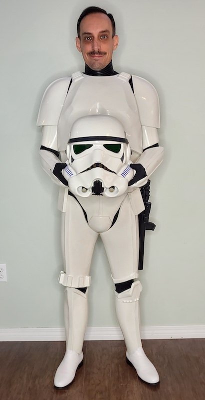
I had my first troop today!!! It was a comic store opening. A pretty low-key event, but still a lot of fun. There were about a dozen of us in attendance. Two TKs. I'm the shiny in the middle above. The armor performed flawlessly. Everything stayed connected, buttoned, and aligned throughout the ~2.5 hour troop. It was comfortable and easy to move around in. I have no complaints at all. When test-fitting, the armor felt pretty tight around the neck, but it didn't feel bad or bother me while trooping. My bucket was also very comfy. The @ukswrath comm system worked perfectly and everyone could actually hear me. I kept one fan running and stayed cool the whole time. I'm looking forward to adding the SHA and seeing if it'll all fit inside with the big headphones I chose to hack up. Visibility was also amazingly good after removing a bit of padding and shifting electronics around. A+ experience!!! Will troop again.3 points
-
Looking nice, sir! I noticed that your bucket is riding a bit high, and I'm thinking that you have padding in the top. Removing that would bring the helmet down and significantly increase your field of vision. Trust me. If you can raise the bells it would give you a better overall look. As for the forearms, I would split the difference on the length- (raise the left one a tad and lower the right a bit. SUPER job on adjusting the TD clips. If I could offer one suggestion, it would be to change the direction of the bend on the bottoms. If they face outward they can scratch your armor where the metal meets the plastic. Facing the bend the other way as shown would prevent this. The Velcro on the back like you have it is always a great idea to prevent scratches as well. Note how bottom bends face away from the wearer.2 points
-
I printed a full F-11D kit using @The5thHorseman files probably around when TLJ came out. I'm finally beginning to do something with it. I started with a full inventory and assessment of what I have. I have come a fair way in printing and also now have a resin printer which changes things a bit also. I am going to be reprinting most of the smaller parts again on the resin printer to give better detail for less prep work. I did start this 2 days ago but a silly mistake ruined a full plate of parts, so that's currently back on the printer. I'll post pictures once I have some. I also want to add some basic electronics to the weapon. I want to have the red LEDs in the magazine and Hengstler, and also the front torch. I am struggling to source the one listed in the build guide PDF. Instead I have found the smallest one I could on eBay and will see if I can make it work, modifying the parts as needed. The rough plan is to run all of this off a single battery and 2 switches. I have modified the magazine file to add a place for a switch and hollowed out the Hengstler as a possible battery location. I have also added some wire paths to some files, but on others I will drill the prints out and then fill the exposed infill. The modified magazine file. Once I prove these work, and any other modded files, I'll make them available to anyone who wants them. For the front torch I want to be able to choose when it's on or not for photos/effect in darker rooms. I am hoping I'll be able to gut it and run some wires down the barrel to the battery and switches. I have bought some 12mm tactile switches which as luck would have it are almost perfect for the blaster trigger. They are meant to be PCB mount so I have modded one slightly to fit in and still have somewhere for the wires to go. Mine are 6mm height, so a 7mm would probably be even better. I'll solder on some wires and then glue the switch to the trigger, and a thin EVA sheet to the other side as a bit of filler/padding. I will be reprinting the handle for better quality so will run some tests on the old parts to check it works. Biggest issue with this project is fitting it around the armour build so I can get parts sanded and primed for paint once the world reopens.1 point
-
Greetings Imperial Citizens! TK 15122, AKA Vapor, reporting in. I just got my official acceptance into the Legion this morning as an ESB Stormtrooper. I'm currently serving with the Rancor Raiders in the Mississippi Garrison. I'm 34 years old, currently serving in the U.S. Air Force. I've been on Active Duty for 13 years now, and am currently stationed in Mississippi. In my free time, I enjoy cosplaying (in and outside of the 501st) all kinds of comic, video game, and anime characters at conventions, video games (specifically RPG and FPS), podcasting (hosted a few and worked as a narrator on The NoSleep Podcast), taking long road trips around the country, hanging out with my buddies, and encapsulating myself in 80s/vaporwave culture, aesthetic, and music. I've wanted to be a Stormtrooper since I was a little kid, and it probably played into me joining the military in some aspect. Getting the big brown box was a dream come true. I'm really looking forward to hopefully trooping with you guys in the future or meeting up at conventions. Vapor / TK 15122

 1 point
 -
TK 15122 requesting access! https://www.501st.com/members/displaymemberdetails.php?userID=34379 Thanks, Vapor1 point
-
Congratulations Trooper! That's one good looking set of armor, I'm sure you'll enjoy trooping in it!1 point
-
Congratulations trooper and welcome to the ranks You can now stormtrooper access here1 point
-
So the day finally came... Got my BBB and learned that whew you need to watch some videos just just get in/out of this thing lol RS Props did a great job and now I'm figuring I need to do some minor tweaks. Seems the belt needs a little tlc as it's fraying a bit and those snaps are hard to keep snapped. I wonder if some velcro might be a better option? I just added some glamour shots from the back yard. Thanks to my wife who's been helping me along the way. She's a trooper... pun intended I think I'm getting pretty close. I just ordered all the parts to customize the interior of my helmet. iComm system is in hand and just waiting on my fans from Troopacoola!1 point
-
Congratulations on your first troop Adam, hope it was everything you were expecting and more.1 point
-
Thanks Germain, I've got those now. Baked in or not the step file hopefully will be a bit easier than working on the raw meshes which can be really slow for tasks like Booleans and so on. If I need to make any further modifications I'll see how I get on with these.1 point
-
Browsing various threads here, I noticed something about my bucket... BEFORE I didn't do the best job of painting my vocoder. It's not terrible, but there's room for improvement. The AP helmet is pretty soft in this area and the vocoder isn't well defined. I struggled with figuring out what to paint... 2 years ago. When this build started. heh. Also, the hovi tips are not so white. Again, not terrible, but could be improved. These are the built-in-speaker tips from Ukswrath, which I really really like. They just need a bit more white. AFTER! While maybe still not perfect, this is a LOT better IMO. Worth the half hour of careful painting, measuring, and repainting. I also redid the inside of my bucket. I want to get the SHA and headphones built in and working, so I needed to move some stuff around. The ICOMM and amp used to be basically next to my ears. I had some padding at the top that was making the helmet flop around. And the USB battery used to sit in the very back, which caused the helmet to always be slowly pivoting backwards and obscuring my view. Everything now fits better and it's much more comfy. Happy with these small changes. I managed to drop my Hyperfirm and the counter popped off. It was held on by standard CA glue which was pretty crusty and sparse. Black stuff to the rescue!!! I sanded down the blaster side and matching side on the counter to remove all old CA glue. A quick coating of black stuff... Repaired. Hopefully much more resilient than the old crusty superglue. And finally, more magnet boxes from @Scimitar! These ones are in a slightly sexier black, complete with shadow trooper-sourced ABS covers. These are going on the other side of the torso to keep alignment correct. And since there's far less visibility on this side, I installed them a bit differently. Each set of magnet boxes got polarity and positioning figured out, then set aside. Then I sanded and E6000'd the area and all boxes. Next, I installed a box on one half of the armor, being very careful to line up the seem edge with the box edge. Some blue tape was applied to keep the box from shifting forward when it's buddy appeared for glue-down. Finally, I added the matching box, applied a little force to keep them in place temporarily, and repeated on the 2nd pair above. Located, glued, placed, and clamped. And there they sat another 2 days. Everything was dry enough tonight that I got to try things on and inspect the alignment... and it's just epic. No bulging. No gap. The belt doesn't skew anything. Nothing but perfection. These magnet boxes are something else. Huge thanks to Eric for sending them. And, well, everything else in this build. It would still be in a sad brown box in storage if not for him.1 point
-
Note sure if you still need anything at this point, but I can send you the 3D files in .step format if you'd like. Just keep in mind that most of them will have edge fillets 'baked in' which might get in the way.1 point
-
Prefect is the enemy of done. So I've been messing about again. With new trigger 1 in place I decided I preferred the placement of it to trigger 2 (the rear blocky one). So I wanted to make this the switch that activates the torch. I now am able to use both triggers with a switch should I want to, with would be brilliant for a full sound and light effects if you're into such things. I am not I just want the torch and the red LEDs to work. I've changed the new trigger to allow the use of a micro switch which works really nice. The biggest issue was securing it, I could have used glue or something like that but I wanted to be able to remove/replace it if needed with out having to reprint the part. After a lot of messing about I opted for two M4 grub screws which centre on the mount holes on the switch. Sadly these will be visible from the outside but will be on the body side, and black in a black part so you will need to look for them to see them I think. The micro switch fits along the length of the blaster so the trigger will act on the switch nicely. The positioning is just perfect so that the switch will also act as the return spring, and gives about 3-5mm of trigger travel. It's not a huge pull but it's enough to know you're doing it. The extra big hole in the above part is to allow wires to come through from trigger 2 if needed. The microswitch being offset gives the room for the wires. Once sanded the holes blended in a bit nicer, I've tapped them M4 with a tap so the grub screws go in nice and easy and should mean the paint won't get trashed at assembly. The rear barrel will sit above the black part so I've updated it to add the extra holes for the wires from both the triggers to be able to come through. This is printing as I type. I also did an inventory and have noticed I either never printed or lost a few parts so I'll need to get those printed.1 point
-
Armor really should be fitted TO you, maybe unless you are the perfect 'standard size', and even then. They are NOT one-size-fits-all, or even most, so very few reputable vendors offer premade/ready-to-wear armor, and the trend is towards building yourself or working closely with a vendor on a commission. Since fitting is an important step, the best course of action is to find someone local to you to help mentor, or you may still end up with an ill-fitting suit, even with a commission, and it's a somewhat expensive costume to risk it on. If you really want to be a stormtrooper, and look good, it's worth investing in the tools and skills to build your own, imo.1 point
-
I did some sanding today between jobs and decided it was time to glue the "folding stock" parts together. The seam needs to be filled, but I actually got a pretty good line with just the glue so filling shouldn't be too labourious. I also decided to re-model "Trigger 1" whilst I am mucking about with fusion. The supplied one is a big blocky and chunky and I'm not a fan of it. I saw in a Facebook group some one did one based on a real one so I did the same. Now I am no gun nut so I just googled and ended up using an H&K MP5 as a basis. Now it's not exactly canon but it looks better, will hopefully feel better and also I could add a switch if I want to. There should be room for a small tactile switch, though a micro switch would be better. I did rotate the angle from the reference image to match the model as I'll need room to get to trigger 2 but I'll do a test print and see how it goes. Again I've only ever used 1 fire arm in my life so don't expect too much here, I just wanted something a little more realistic.1 point
-
And we are back in business! E3D delivered the parts nice and fast but it was project time that was short. I rebuilt the whole print head with new plastics and it's gone together much better as the parts were better printed this time. I've printed and rough sanded the new TLJ style rear barrel (with some extra holes), a new Hengstler bracket (also with extra holes) and the TLJ End cap (not sanded). I recently swapped to use esun PETG and it's proving to sand really nicely, considerably less work than the PLA and PLA+ I have previously used. I also quickly threw the back end together for a rough preview and I think it's come out really nice. I need to print the new clip but that means swapping the resin in the Elegoo Mars which is just a faff so I keep putting it off. I also need to check I actually have enough black resin left. Really all that's left now is a few coats of filler primer on the new parts and getting it all smooth then final colour and electronics. So another 24 months then? In seriousness there isn't a huge amount left that's not filling and sanding. The electronics will more be a case of fitting, and ordering a the connectors I need for that. Winter is indeed coming so not sure how I'll work around the cold and wet but I'd like this done by spring now if I can.1 point
-
Took the whole head assembly apart, it was a real mess. The heat block and sensors are done and need to be replaced. The heat break I was able to remove which is nice as it's a titanium one, needs some more cleaning the PETG out of the threads though. The heat sink was covered in thermal compound but cleaned up really nice with some IPA. I have a spare heat block I could use but I'll need to order sensors anyway so I'll get a nice new one. I have the steel heat break that came with the kit last year as well so I have choices. Once the new parts arrive I'll need to rebuild the printer with some new plastics I printed in Galaxy Black for added sparkle and get it all calibrated and running again.1 point
-
Iteration #712 (actually v12 according to fusion but that's 12 saves for all the mods, but most are this) Top: last version Bottom: new version Not a huge amount of changes Moved the whole cocking slide down a fraction as it was a shade too close to the top/rear sight cut out. It is now about the same gap as the TFA source STL, +-"0.no one cares" mm. Extended the cocking slide so it's only 1mm from the Hengstler mount. There is a 45° chamfer at the end to help with printing, and also blend in the end a little so it's less abrupt. I added some more holes for my wiring setup. (there is a version with out all these) Pretty happy with this now. If anyone else wants them I will publish but for now I'll wait for a 2nd set of eyes to check my work.1 point
-
Hot off the press: Seems good, though I'm going to extend the cocking slot to be around 1-2mm from the mount for the Hengstler, so around 1/2-1/4 of the current gap. Currently it's about flush with the end of the counter so it will probably be a little ugly, and extending it will hide that join. It's hard to see on the reference exactly how far this goes but "behind" the Hengstler seems a reasonable guess from what I can see. And roughly assembled for some context: Finally old (with primer) vs new (printer fresh) The sizes for the slot were all measured off the old print so are all the same +-0.5mm.1 point
-
This update is based on this thread: I've spent some time this evening editing the @The5thHorseman files to update them to TLJ specs. I've used Fusion 360 to do this with the new mesh workspace updates. This wasn't too bad, having access to the source objects or STEP files would be better but the new space is pretty good. Previously I used Meshmixer for things like this but it's now discontinued and the features are being added to Fusion. This actually makes things a lot easier as I have access to the normal modelling tools to make the objects to amend the mesh's with in the same workspace. It also seems to crash less. Some edits are basically invisible and you won't notice any of them as edits, others required me "fudging" things a little so there are small flaws but I doubt they will even show on a print. Time will tell on that. First up 2 extra holes in the front barrel, I have already drilled mine out so I may or may not actually print this one out as I'll also need to reprint the fins. Next the end cap. The TLJ version has the recessed section top completely removed. There are a few flaws to this one but they don't seem to show up in the slicer. The end clip is squared off. I'm not sure I have this correct as this change has the worst visibility in the reference. The biggest change is the rear barrel. The cocking slide has moved from the left to the right, the handle is not needed anymore, the "ring" around the barrel is also removed. This was the most fiddly and required making a few shapes to fill the old slide and ring, and also cut out the new slide in the right place. I also removed the internal feature from the old cocking slide and added it to the right for the new one. There are also some, but not all, the holes needed for my electronics, 1 hole I'll need to drill still as lining it up is awkward. The flaws on this one also seem to not be showing in there slicer. I'll start printing tomorrow if time allows.1 point
-
One of the many things that I've been doing over the last 18 months, not this clearly, is electronics projects. So rather than messing about with strip board for the electronics on this I've designed a board. Nothing to complex, just a simple hub that makes connecting it all up easier and means I have something to put the LEDs on. I ran a quick test of the LEDS and battery I plan to use and its all very bright. I actually swapped from these clear LEDs to some red colour ones after this as they better diffuse the light so should light up more evenly, and are even brighter. The button will be behind the main trigger so I can easily use the torch for short periods of time and not worry about battery too much. The red LEDs are pretty bright, but hopefully the paint will stop them shining through the resin parts! I have been trying to paint some of the blaster parts over the summer but it seemed I was inept and managed to drop parts with wet paint into the mud, on the floor and scratch bits that are done. I'll get there eventually, I just hate painting.1 point
-
I've figured out a way to mount the battery now, and it all just about fits. The final item is a bit different from the images below as I've added a rear foot to help keep the mount level in the blaster as it was tipping due to the batteries weight. I am considering changing the foot design again to make it easier to print with less support. The battery will be attached to the sled with high strength double sided tape, either a VHB or some gorilla tape I have. Note: no rear foot yet! The sled also has a slotted hole for the screw so it actually ends up clamping the charge board in place as well. The end cap will be mounted via magnets to a plate that will be glued inside. There is a small cut out for the screw that holds the silver bit on, and a recess for the on/off switch to sit in. Today I was looking at a photo of a rank of TLJ F-11Ds from production to replicate the piccatiny rail and mount and noticed 2 extra holes. So clearly I needed these on my blaster. I started out by measuring and marking out based on the images. I measured the existing holes to be 12mm so predrilled with a 3mm pilot drill. Next up was a 12mm forstner bit, so I was about to either have a nice hole or a ruined blaster. Ominous forbidding.... 12mm was too big, it looked HUGE compared to the standard holes. I swapped to 10mm wood spur drill for the front, then stepped up to 11mm with a step drill and looked pretty much spot on. To fix this was a hassle. First I cut a small piece of 1mm styrene, bent it slightly and then super glued this behind the hole. This was then filled with a 2 part filler in 2 passes. I used some masking tape to minimise the area this affected, and removed it whilst the filler was still soft. To sand down the filler I used a sanding stick to ensure that I kept the filler level to the barrel and no big gouges or lumps where left. I then re-marked the hole and re drilled with the 10mm wood drill. The step drill was too long for the rear hole, the front had an opening on the other side, so it only cut about half way through. To finish I used a small round file and a pen wrapped with sand paper to clean it up. To finish the repair I sprayed on a couple of coats of filler primer. Again to minimise the impact I masked off most of the barrel so that I only sprayed the repair area. Once this has dried I will sand out the area again to smooth out the lip left from the tape. There's a small mark visible up close but the end result is pretty good and won't be visible unless you're looking up close.1 point
-
Seems I'm overdue an update. I've spent some time working on my blasters in the last week as I had some time off work. Since my last update I reprinted a number of parts on my Elegoo Mars resin printer which gives a far cleaner finish. Some of these are just better versions of the previously FDM printed parts, others have been modified to better suit my specific build. I still have a few bits to print, mainly the detailed hand grips, but they failed on previous attempts and I have yet to re-try now I am better at setting up resin prints. So first up is the Hengstler box. This was modded to make it fully hollow, as I did intend to put the battery here, and a hole was added for the wiring between the screws. I also had to modify the mounting bracket as well. Next up the other side of the rifle for the magazine. This has been modified to add a slide switch. This will be the on off switch for the lighting. It's subtle easy to access and I believe reasonably accurately placed. This was a bit of a pain to mod, and I was only able to get 1 screw in. I have also finished up the basic wiring for the torch at the front, this also has a resin printed ring. To get the torch to fit I had to hollow out a lot of the mount and add some reinforcement on what was left. The wiring is a basic connection commonly used in RC I think. It clips in nicely and will mean I can remove/replace the torch if needed with out having to cut things. As the bore is larger I also had to Dremel out some meat in the main blaster section too. End result should look pretty nice I hope As I now believe I have all the needed holes for the wiring in place I have started sub assembly so I can start looking towards final paint. Basically all parts that need to be glued in place have been. So the hengsteler connector, front hand grip mount, side mount, barrel rails, flash suppressors etc. It was also time to check the fit of the barrel tip. I have 2 of these, one FDM one resin. I drilled the holes to 1/4" as I don't have a 6mm and a little clearance isn't a bad thing. I like to have through holes be clearance holes where I can as then there's no mucking about trying to line up threads later which can cause them to get stripped, which I did on my 3D printer. Finally I have started figuring out the power situation for the blaster. Based on a design from the BlastFX community I came up with my own version. I am using a 650mAh LiPo battery as they are small and powerful. To charge it I am using a TP4056 board. This gives USB micro charging with over charging protection. This updated version has separate connections for the battery and the output which I believe means it protects against over discharge. You hook the battery to the B+/B- connections and the circuit to the OUT connections go out to the circuit. The original idea was to put the battery in the hengstler where it would be easy to remove. I didn't like the long power lines from the charger this would mean though. So based on the other design I have created a mount that fits in the end of the barrel. This has a slot for the board to slide into, which is then secured by an M3 screw which keeps things simple. A small hole next to the USB socket lets me see the status LED of the charging board. Still a bit loose. I need to adjust the design in a few places, this was a first test. Above the USB socket is a 2nd DPDT slide switch. This will allow me to completely disconnect the battery from the charging board for storage and transport. It does mean I'll have to remember to turn it on to charge the battery. The extra length is intended to be a place to mount the LiPo battery. I am not exactly sure how I will do this yet, maybe cable ties or some adhesive foam tape? I need it to have a small amount of movement as I don't want to crush the battery with a clamp. The 2 holes top and bottom are for neodymium magnets, 4x2mm at the moment. There will be a matching plate in the end cap that will have magnets in too to allow it to clip in place but still allow access to the charger and main power. I am yet to work out how I'll attach the inner section as I would like to avoid glue to allow access to the battery when needed. Grub screws may be an option if they can be hidden but I'm not sure the wall is thick enough. Other than the last few parts I am almost ready for paint. I'm hoping to try go to Halfords and get some matt black and Appliance white soon now that shops are opening up again. All parts are sanded to 320 which should be good enough for the colour coat. My primer is quite coarse so if I've missed any spots I'll need to go back after the first coats and fix those.1 point
-
Okay some more progress on the torch which is totally worth all this effort I am sure..... At least it's a distraction from breaking the 3D printer. So I ordered 2 of these torches from ebay that looked small enough. In practice they are too long and only just about fit down the available space, after a big mod to Germain's file to make it. First job was to cut one open and see what I had to work with. I measured down the inside of the barrel to see where I could cut. Once inside I could pull the inner section out of the outer metal barrel and found it's just a 5mm LED in a holder that runs off 3 1.5 LR44 batteries. Sadly the leads on the LED are too short to solder to with out melting the holder but a standard 5mm LED fits the holes just fine. The first torch I destroyed modified I cut very short, and a bit sloppy. These have a zoom function where pushed in is wide angle and pulled out is focused. The location of the cut was perfect for the LED mount but left no options for the focus. With that in mind I cut the second a fair amount longer, about 25mm from the chromed ring. This seems to be about perfect. I cut the inner down to the minimum for easy access when soldering. I also sourced some VERY bright LEDs, so bright that to run off a 9V I should be using a 1 watt resistor (I didn't but it was short bursts) and it projected a spot on the wall across the room. The cool thing about them is they are 3.2-4.5V so I can run one right off the 3.7V LiPo without any resistors. They also are projecting LEDs as I think they are meant to make torches with. I have a stash of JST RCY connectors that are nice and easy to connect. They may be a bit big for some of the other connections but here I think it will be perfect, Though I have some smaller ones too if that doesn't work. The plan is to solder a short connector direct to the LED with heat shrink to prevent shorts. This will then connect to another wire in the under barrel which will run down the length, through a hole into the main barrel and then through to the core of the blaster where I can wire in the switch and the power as required. I'll probably wait until I get the soldering iron out to weld the next armour sections before I do this work.1 point


.thumb.png.a6ed6181c5fa602617131001cb8f5718.png)