Leaderboard


Popular Content
Showing content with the highest reputation on 03/05/2018 in Posts
-
Dude!!! That's some serious work you've put into the clip. It looks great!! One question: and I may be "nit-picking" but... is the LED maybe sitting a little "tall"? Mark2 points
-
Hi all, I've been on this crazy magazine clip / housing adventure for quite some time and I am pleased to share how I've finished allot of this so to continue with the trigger group with BlastFX components that I've started already. The craziness was in high gear when attempting to scratch build the magazine clip. Although initially, had settled on using spot putty for the final surface material for the magazine clip, it proved not effective as it was susceptible for cracking over larger areas so resorted to good old green stuff. I applied green stuff 'skin' overtop the styrene / spot puttied surface and it worked out good! Dries hard and sands well! I follow through on this update with this modification along with getting the magazine latch and cap (with T-Jay's LED button) along with some magazine cap internal components like the cap bottom mechanism with compression spring as well as install of the five magnets that came T-Jay's completion set. Created styrene plastic magazine latch loosely following SMG references. I choose screws that were the style I wanted but I didn't have a smaller size on hand so I created the latch slightly bigger than how it is for real. Relative to itself, it's accurate enough for me - template cut and fitted Green stuff applied to styrene plastic magazine latch to fortify Custom magazine cap created using styrene, fortified with green stuff, aluminum sheet formed underneath with guides for attaching on to magazine clip opening. Letter punch to be applied to green stuff to capture text Template applied and button position on magazine cap placed Text captured on magazine cap - done so before green stuff fully cured - sanding to follow Magazine cap guides installed on body - bent aluminum sheet, following after Tennatlim The locking guides for the magazine cap glued into place. I would later get green stuff into the open grooves between the plastic and the aluminum on the side Created green stuff ‘skin’ for 1-1/2 Wave side of magazine clip - details cut out and pressed / molded into place with close attention to application so to capture relief Various views of custom styrene magazine clip with green stuff ‘skin’ and end cap installed Magazine cap attach brackets installed Magazine cap - under plate locking guides in place, text added. Green stuff added to hide gap on the sides. Press button on top still need install Test fit of latch and cap on Magazine Clip inside Magazine Housing Magazine latch - detail with screw, two cut to length and held together with heat shrink. Still need to place in concave shaped plate on the top Custom Magazine latch with cover installed. I turfed the idea of using screws to attach and simply used E-6000 Added button to magazine cap - T-Jay LED part has bottom lip so made hole to later be kept in place with elastic fabric. Magazine end cap with push button installed - elastic fabric installed underneath to enable push and return to original position. It would later be up against the bottom mechanism and get tension for the compression spring to enable good push tension and return on the button Carve into magazine well to install two magnets using Dremel tool and glued with quick set CA glue Magazine clip magnet housing - shallow plastic channel used with styrene plastic cover. Hole added to enable spring contact Magnet housing on underside of magazine clip - three magnets installed - the plastic on the underside just so happens to mimic the rollers of the follower much like the real SMG Magazine clip magnet housing is topped with styrene plastic sheet to provide flat surface for the bottom mechanism compression spring to magnet to and have a flat surface for it to stay upright. The plastic housing pushes against the inner walls pretty tight, more so than the force of the magnets so it is able to keep in place Magazine clip bottom mechanism with compression spring installed with magazine cap overtop. The details of this bottom mechanism was obtained from studying Tennatlim's post View of installed magnets on magazine clip and magazine housing Aerial view of custom built and/or modified components of magazine clip and housing Various views of magazine clip and housing - completed!!! Thanks for reading! Cheers and happy building!2 points
-
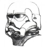
When in doubt refer to reference photos .2 points
-
Hey guys, I'm really loving all the paint comments. It's great to get a "collective" opinion from people who have experience. Ultimately, it's up to you (the builder) as to how much work you are willing to put in what what paints you have available. I ran a few more "tests" and managed to get some "wrinkle" results with the VHT Wrinkle Plus. Maybe I should have read the directions first. So, it appears as though some paints work differently. The Rust-oleum and Tremclad seem to kind of "spit" out the paint for a textured surface (not a fine mist) and then rely on different paint densities and reflections to give an apparent hammered effect. Doing several light coats (with a bit of dry time in between) gives more "spit" and as a result, more texture. The VHT is different. It seems to rely on a "constriction" effect as the paint dries to form ridges. It goes on smooth and wrinkles over time. I got fairly major wrinkle results following the manufacturers directions. Spray a heavy coat, wait 5 minutes, spray a heavy coat at a different angle, wait 5 minutes, spray a third heavy coat at another different angle, then wait two hours. After 2 hours you should see a wrinkle effect. If you don't, you need heavier coats. Then you have to wait 48 hours for the paint to completely dry. Here's what I saw: Now, I think I know why they call this a Wrinkle effect, not hammered. I would describe hammered as little pits or dents or bumps in the paint.....either as a texture or as an effect. This wrinkle paint I would describe as tiny little lines all over the paint. Almost as if someone took an X-Acto knife and put billions of tiny cuts in the paint, all perfectly straight but going different directions and probably 1/2 mm in length. It's an interesting effect, but maybe too much? I wonder what lighter coats would look like? From what I'm learning from hammered paints, probably a lot of this wrinkle texture is coming from the hard reflections from the gloss paint. Hitting it with matte black or a matte clear coat should really reduce the wrinkle appearance... It kind of hard to capture in a photograph. It looks ok. Kind of different. You could probably get a nice texture with more experience. But here's my concern, if the VHT Wrinkle Plus needs 2 or 3 heavy coats to wrinkle, that will probably decimate any detail in the resin. I don't think I want to take that chance. This might be the type of thing you apply in a few areas to look like rough metal and probably not something you want to spray over the entire barrel. I think I'll stick to the hammered paint and just end up with a less "textured" finish. Mark2 points
-
Looking at that pic I believe that may be the case. I'll align it with it further back and see how it sits than once home from work.2 points
-
Looks like the ears are on the correct sides. The bottom just seems really far forward in the picture. Hard to tell at that angle.2 points
-
This is for the hand painted look. if you seek perfect lines you best get some decals. Items required: Humbrol Paint. Tamiya mask tape. 2b pencil (sharpened to a pin) to mark the ABS. Pen to mark the tape. Steady hands. Mask some parallel lines. Press the tape down firm so bleeding does not occur. (This is when the paint seeps under the tape). Tube stripes Using a spacer for marking out Draw the lines in with a 2b lead pencil. First coat completed but will even out some of the lines with the second coat. Time to remove the masking tape (Tamiya). I started by lightly cutting the paint line with a blade but soon realized i did not need it. Just one bleed area on the first stripe so will clean this later. Happy days.1 point
-
It’s been a long journey and I know it’s only just begun. Thanks to everyone who contributed to my build thread and to everyone who participates is this community. I found great value reading through various threads and how tos. My journey to the 501st began in December 2016 when I ordered my Anovos OT kit. I received my kit in January 2018 and immediately began building. A fellow garrison member commented that I completed my build quickly, but it actually took me well over 100 hours. I stopped counting when I realized I had reached that bench mark. My family didn’t recognize me when I finally emerged from the garage and I had grown a beard in the process. I was frustrated at times and often asked myself, “why am I doing this?” All my frustrations disappeared when I first put on my completed armor. I am currently working on a Disney blaster conversion, but am itching to start a new armor build. This hobby is addicting! I am looking forward to my first troop and to finding my next project. Thanks again everyone.1 point
-
I wasn't feeling so hot yesterday but still managed to get lots of sanding done on the forearms, biceps and shoulder bells. I also started gluing the left forearm yesterday and left bicep today. It took quite a bit of wrestling to get the forearm to cooperate! Sent from my SM-G950U using Tapatalk1 point
-
The result of your wrinkle paint looks absolutely correct, Mark. You have exactly followed the instructions and got the same surface and glossy finish, that I once had. You can reduce this by adding a very thin layer of black paint.1 point
-
Thank you Tony!1 point
-
Yes, and the sides don't have to be exact or perfect.1 point
-
Hey thanks Wayne!1 point
-
Keep up the good work troopers1 point
-
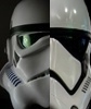
https://www.whitearmor.net/forum/gallery/image/882-anhherostormtrooperhelmetleftprofiljpg/1 point
-
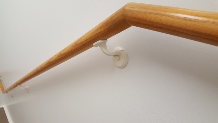
Yes and this doesn't have to be perfect. Canon ears were kinda staggered. Every helmet I build I try to align it like this regardless or series.1 point
-
No troubles! Its always from a certain point of angle I just asked the same question about the gallery1 point
-
Sorry about that...not sure why the other reference that I looked at made me think it was the wrong ear. May have been the angle of your photo. My apologies! I was in the process of looking up another reference and my computer froze. Tony, is that from the gallery? I looked for something like that and did not find it but perhaps I looked in the wrong place?1 point
-
Wow! Excellent work...and patience! Looks fantastic Jesse! Sent from my iPhone using Tapatalk1 point
-
Photos link codes corrected and additional photos added for lens color1 point
-
Looking good trooper. Nice fitting armor, well constructed. Good luck!1 point
-
They said it was out of their hands. Part of the licensing they had to abide by to be able to produce the helmets.1 point
-
My ATA helmet arrived and man am I impressed. The quality and the supplied hardware at this price point ... just fantastic. I'm going to build this bucket to centurion level and was just wondering if there is anything that came with this kit that should be replaced with something else. The neck trim is "s" type and the ear screws are brass. Everything looks good to me but I'm still new to this.
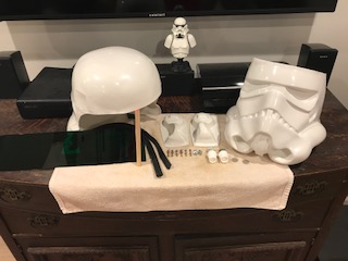
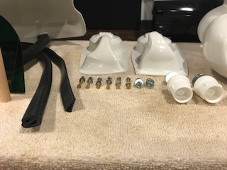 1 point
 -
Awesome [emoji41] !!! I have a WTF as well ! Sent from my iPhone using Tapatalk1 point
-
Back on the E11. Finished my Monster MSE Droid [emoji16] Soo..... I realized the Shapeways scope insert for the blastfx scope sight didnt have the m38 imprint [emoji58] so, I cut off the inner part and sunk it into the scope so the doopy scope end fits over it. Had to carve and mold a holder for the red and clear lens.. BUT i think it will work! All that to save a few bucks and not reorder the printed one now available uggg Also, got a bigger clip off ebay. Its plastic and hollow so I hope to use it as my battery holder! Also hollowed out the doopy counter box and fabed it to hold the lens i got off ebay. This will also house the blastfx counter. Also to save $ from the nice shapeways box for the blastfx. I think it will work out [emoji16] Got the shapeways trigger hole in the handle. It is supposed to work with the blastfx switch kinda hair trigger like without a spring so we will see. Also drilled a hole down the handle for the rumble mechanism. Getting close to paint time. Sent from my SM-J700T using Tapatalk1 point
-
I am continuing with cover strips. I have to glue as much as my magnets and clamps allow, then wait for things to set up. It’s slow, but I do like the forgiveness of the e6000. Since things were going slow, I got started on glueing the shins too. CA for the inner strip and e6000 for the outer. This clamping session will complete the arms and shin joining. Cheers! Sent from my iPhone using Tapatalk1 point
-
For the gap, just ad a piece at the bottom....for the issue with the coverstrip (if you choose to fix) the only option is to remove and reglue making sure it sits even on the seem...and if there is need for a gap for the entire seem in order for the cover strip to sit even, then a full length inner strip is prefereble1 point
-
I'm going to have to get creative with the placement of everything inside the helmet, my head isn't exactly small either. lol I've done a test run with the speakers and they're awesome, I'm looking forward to getting everything in there though. FWIW, the speakers aren't much heavier than the AP Hovi Mics, I think mainly because the attachment hardware is all nylon/plastic vs. the metal on the originals. Speaking of which, I solved the spacer issue with the Hovi Speakers (in this case) to my satisfaction, I tried a few different ideas and this is the one that was the simplest and worked the best in my opinion. I bought 9/16" x 1/4" rubber grommets and 1/4" nylon washers from Lowes (there were no washers included with the Hovi Speakers, so I was going to add them anyway). Note that the sizes used would be different for the AP Hovi Mics: I put the grommet directly on the back of the Hovi Speaker: And then I attached it to the helmet using a nylon washer under the nut. On one side the grommet bottomed out before the Hovi Speaker did, which is what I wanted so it could compress against the helmet. On the other side the speaker bottomed out first, so I added two nylon washers between the speaker and grommet and then the grommet bottomed out first. Everything is then firmly finger tightened: There will still be a gap on one side of the speaker and this is normal/unavoidable due to the shape of the helmet recess. But the speakers are firmly in place, oriented well, and the pressure is evenly distributed against the grommet on one side and the washer on the other: After doing that I painted the first trap (helmet came back apart so I could paint under the brow trim and so I could touch up the plasti-dip on the inside): Parts list from this post: 9/16"OD x 1/4"ID Rubber Grommets - x2 (Specific sizing for Ukswrath Hovi Tip Speakers) 1/4" Nylon Washers - x2 Minimum - Extra may be needed as spacers ------------------------------------------------------------------------------------ And right before I had taken it apart, my 21 month old daughter put the helmet on herself and ran around the room yelling "HELLO" because that's what I was saying to her when I was testing the speakers out. This is why I get nothing done quickly. Haha!1 point
-
Yes, you are ok to remove them. As Randy said, they will chew up your boots. Also, the shins are supposed to be tight to the boots, which means you need to remove the return just the same as the bottoms of the forearms.1 point
-
Heh...I figure if I can get them to the smallest "default" and have it work for me, there is less of a chance that I will make a fatal error! Sent from my SM-G950U using Tapatalk1 point
-
What an idiot! Jk. Your not an idiot your like the rest of us. Use an app like tapatalk (I use) or imgur. Sent from my iPhone using Tapatalk1 point
-
OH MY GOD!1 point
-
#5 EIB added today1 point
-
Glad you mention all the above, especially in RED. I get flack from some in my garrison because I don't troop enough, which equates to 1/2 dozen a year if not more. I reply "You make dreams come true your way and I'll do it mine".1 point
-
Got the rest of my armor yesterday from KWDesigns Sent from my iPhone using Tapatalk1 point
-
....when everyday things start reminding you of it.
 1 point
 -
Well, you've seen mine in person now. Seems mostly bullet-proof. Your garrison mate can certainly have a look through my build thread. It went to Centurion without issues. I used inner and outer cover strips to reinforce the joints on mine. Has held up quite well, I'd say.1 point
-
I've seen 20mm, 25mm, 30mm, etc. Is there a size required for Centurion? I don't see anything specified. Obviously you don't want a 6" wide cover strip on the backs of your legs, nor do you want a 5mm strip, but is there some wiggle room in the cover strip size, as long as it's standardized within your own limbs, or is it clarified somewhere?1 point
-
OK guys, after much help and hard work from Mark at CFO here is the final tube template for an accurate 38.1mm Sterling tube. Every detail has been checked and it also includes the optional end cap lug spacing for those with hollow end caps. This will give you a genuinely accurate Sterling receiver for your E-11 kit. It comes in 3 different PDF's. One is a full size template for those with access to larger format printers and one is a two page PDF which splits the template in two (includes alignment marks) on to internationally standard A4 paper size for easy printing. The final PDF is the same two page set up but on Letter sized paper for our American brethren. Not only that, but after a lot of math (not my favorite activity ) I have an accurate template scaled up for the common 40mm pipe. It is important to note that this template has NOT been scaled up across the board, or by percentages. The tube circumference has been enlarged and the details carefully moved in tiny measurements to maintain accurate relationships but all dimensions and certainly the length wise distances remain accurate. Admittedly I'm talking about centimeters and millimeters here, but there are substantial differences between this template and any other template for a 40mm tube I have been able to find. Taken from sskunky's genuine Sterling receiver these are the most accurate templates I have been able to create for a 40mm tube. These templates are also attached here in the same three formats (large, A4 and letter) as the 38.1mm templates. There is only one important caveat: for a number of reasons there are questions raised by variations on the placement of the rear folding stock mount. You should use discretion when getting the best placement for your folding stock depending on the origin of your stock. Consider this placement accurate for a scratch made folding stock according to the stock templates we are currently perfecting. And of course, as always, all PDF's remain illustrator editable to allow for community improvement if needed. Without further ado here they are - download and enjoy! 38.1mm Tube Template LETTER Paper Letter.38mm.TubeTemplate.pdf 38.1mm Tube Template A4 Paper A4.38mm.TubeTemplate.pdf 38.1mm Tube Template FULL SIZE Tube38mmFullSize.pdf 40mm Tube Template A4 Paper A4.40mm.TubeTemplate.pdf 40mm Tube Template LETTER Paper Letter.40mm.TubeTemplate.pdf 40mm Tube Template FULL SIZE Tube40mmFullSize.pdf1 point