Leaderboard


Popular Content
Showing content with the highest reputation on 12/08/2017 in Posts
-
Jacks RS Prop Masters ANH WIP Well after weeks of researching, talking and checking build threads BBB day finally came.!!!! Yes Christmas has come early. Received my kit from RS props today. Can’t believe it’s finally here. Ever since I was a wee lad I dreamed of one day owning my own Stormtrooper suit and it looks like I’m one step closer to achieving this. Just a quick thanks to everyone I’ve spoken to on this forum. Sent from my iPhone using Tapatalk2 points
-
That's what I'm saying. In a perfect world, every CRL model in FISD would be Centurion. In a perfect perfect world, every CRL would have L3 standard Legion-wide, and every CRL model would be L3. And there will be unicorns, and rainbows, and someone else will pay for it, and it will be awesome.2 points
-
Now, THAT I’d like to see!! Lol :-) Sent from my iPhone using Tapatalk2 points
-
Re-uploading images lost in the Photobucket apocalypse.
 2 points
 -
TK85421 Requesting TLJE Centurion Status (Anovos) Name: Glen Rhodes Height: 180 cm Weight: 74 kg FISD Name: gmrhodes13 Legion ID#: 85421 Profile Page: 501st Profile EIB Thread: TK85421 Requesting TLJE EIB Status (Anovos) [APPROVED] Garrison: Desert Scorpion Build Information Armor Maker: Anovos Helmet Maker: Jim Boots: Imperial Boots Gloves Imperial Boots Electronics: Aker Neck Seal: Anovos Laser Ax: Scratch build Blaster: JJ's resin1 point
-
Hope I’m not too late mate: Bicep hooks: I used a piece of cover strip abs 3/4” wide by 4” long Mark one end in two segments 1” long, once done trim and sand the edges of the piece so it doesn’t fray the elastic. Break out a heat gun, and have another piece of abs cover strip available to help form the abs when it’s malleable. Heat up the abs, keeping 4” to 8” away, I highly recommend having some heat resistant gloves to avoid burning yourself. You will see the abs start to soften, once this starts to happen, place your other piece of abs on the warm abs and begin to fold it over. Take your time shaping the abs into position, and I highly recommend doing a few practice runs. Once you have the hook shaped, it can be tightened up applying some more heat, and a ruler. Next heat the abs again to shape the bicep hook to match the contours of your bicep.1 point
-
Hi SW enthusiasts! Excited to share yet another installment. Over the past two weeks, I've tackled and continue to do so, the magazine housing. Original Doopydoos Magazine Housing For this piece, I wanted to get it looking and functioning much like an original SMG piece. With some green stuff, customizing a solid aluminum rod and some aluminum sheets, I've tried to push this mod without busting this resin piece =) I begin first by looking to replace the ejector with a custom aluminum build, then I proceed to creating the component pieces that relate to the magazine release button. Grub screw used for the ejector comes from Tino's completion set. Inspiration for creating a working release button comes from Tino as well; he's been a huge influence on getting me to my level of build so far. Although I haven't completed the release button components, I'll share my progress so far. Here I measure the ejector diameter for correct purchase of my solid aluminum rod. I then proceed to using a diamond cutting blade on my dremel, then sanding drum, and finally manually sanding via square file. To get it close as possible to the real SMG part, I filled in the underside, under the ejector with green stuff. With some light sanding, I am able to achieve some of the contours of the underside. In now having set the stage, I proceeded to hollow out the resin ejector. The solid aluminum rod is approximately 8mm in diameter. In using the correct drill bit, the rod fits nicely into the magazine housing. I discovered, use of WD-40 is helpful to catch the metal shards and also good for lubricating the hacksaw blade for cutting. Adds smell to the task and drippy but with cardboard placed underneath, no biggie. Here is the test fit for the custom ejector rod, I like it! This hear comes the tricky part, trying to capture the ejector bottom that I think, Is used to individualize the rounds for firing. Hacksaw used to get primary shape. Attached my round file to my drill to shape out the curvature outlined with pencil. Crafting bottom portion of housing ejector - applied blue tape as guides after rough mark up using pencil. Cobalt hacksaw blade used Test fit of partially completed lower portion of ejector - quite happy with the contours. Here comes the final shaping of the end of the ejector - Boeing 747 jet tail, here I come! I begin with getting the tail angle then glue the fin using J-B Weld. I'm hoping with it being made with steel fragments, the glue will adhere well to the aluminum, we'll see. Ejector bottom end completed to follow up with light sanding over glue seam area Ejector with fashioned bottom I now proceed to drilling the other way, so that I can have a functioning magazine release button. I use a 5mm diameter solid aluminum rod for this. I begin by hollowing out a place for it using a drill bit. The holes more so align with the position markings on the housing - a little off but the resin around these holes all have to be taken out anyways. I then have to tackle the ejector - making the same diameter hole right through it...this was nerve racking but I managed to pull it off. Here comes the really finicky part of the ejector. If the bottom part of the ejector wasn't finicky enough, the top is even more work. I proceed here to fashion the bevel and also install the grub screw for it. Grub screw had as part of Tino's completion set. I begin by measuring out the grub screw. I needed to use a progression of drill bits. One size smaller is used than what's measured for the final hole drill out as I will be needing to manually screw the grub screw in so to etch thread onto the ejector. Here's the task ahead of me: I begin initially though to mark the bevel location to gauge the correct location of the grub screw. I then proceed to drilling out the grub screw hole. Here's that manual process I was talking about - I used an allen wrench to drive the grub screw into the aluminum to etch threading. For anyone attempting this, wear cloth covered with rubber gloves, I blistered my fingers pretty bad... I finally drive that grub screw right through! In the process, the fashioned bottom of my ejector piece lost a detail part. I will need to add that back on a later time. Now for work on the bevel, I inserted my ejector into my drill and held it against my square file. Remember to wear ear plugs; drill motors get really loud, especially when you hold your head up close to see the shavings up close. Here's the progression of my work - I like how it had come along! Here are some angle shots... I would actually now have to drill a recess for the grub screw to sit deeper - the actual SMG piece has a hole through the entire triangle part of the housing and the grub screw has a straight-long piece attached that would go through this...fyi. Now, I'm pretty happy with my ejector. The task of getting a custom catch was looming...here we go! Here is a photo taken previously, it shows the component pieces involved in creating the custom catch. The catch being that 'foot' looking thing =) Here I put together the catch, via aluminum provided in T-jay's completion set - perfect length. I then add green stuff and contour it, following SMG references. I then proceed to creating the catch rod by precision measuring the rod. Here, I begin to add thread bolt to one end to hold the foot, I mean catch. Pretty happy with the end result. I would follow through by adding some E-6000 to close some gaps between the aluminum and green stuff. I'm a fan of Terry Fox - A tribute to you dear champion!!! Here's some test fitting... Now the task is to carve out the channel for the catch to rest inside. Measuring depth of custom catch piece and taping off dremel bit 194 to gauge correct carving depth so to get ready for carving out resin catch In checking SMG references, I discovered the catch is to poke into the magazine housing channel as a way of locking the magazine in place. So in my work, revealing some hollow-through parts is a good thing!! Here are some test-fit pictures of the catch - it's sitting flush! I now have to work on the button end of things, that will have to be saved for the next update. Thanks for reading folks and for keeping up with me on this snail of a build - cheers! Have a great day.1 point
-
1 point
-
Should be an easy pass, but good luck all the same.1 point
-
Beautiful work mate! Good luck on the approval!1 point
-
I've got most of the images from this thread backed up to the links below. Im missing the ones in the last few posts by dashrazor, I'll try and get those next week when I'm back at work with a working photobucket fix. I'll keep them on my flickr but can't guarantee they will be on my dropbox forever. https://www.dropbox.com/sh/7ds5s7e2aw1014t/AADz0T3zvMPfdJXSdi1ueJmsa?dl=0 https://flic.kr/s/aHsksJm33Q1 point
-
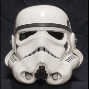
I've seen a few people talk about painting the inside white before going black to help the exterior of the helmet stay bright white. I guess the idea is that going straight black might "darken" the white of thinner helmets when viewed from the outside. Any thoughts on this?1 point
-
Hello Blaster Build Community, I'd like to include a very interesting picture towards the FIS E-11 Blaster Reference. It is a photo of an original Sterling magazine housing from the bottom. It is an intriguing view angle as it shows the catch come up into the magazine housing channel. Builders can have a clearer understanding of function in reviewing the picture. I have certainly benefited. I have contacted the author, Robert A. (swpropman) and obtained permission. Happy building everyone!1 point
-
Now why didn't I think if that...get a bundle of a 100, then print 50 of each certificate and make a mosaic-wallpaper for a feature wall1 point
-
This is what I have found so far. Will post them as I find them. Sent from my iPhone using Tapatalk1 point
-
Well, the only way to get the model changed is to have him upgrade his suit and re-take photos, or else find a more accurate CRL model (e.g. fully suited up person). The key part is that the detail text & photo are correct. There are several other FISD CRLs where the "model" isn't 100% perfect. In fact this is a Legion-wide issue. We have a call out for Centurions to submit photos to replace the non-Centurion CRL models.1 point
-
Hehe. Cheers Daniel - off to pick out some imperial picture frames now... lol1 point
-
Ah, I realized what was wrong. This is now fixed and is consistent with the TLJ TK, e.g. L2 just like the clean one.1 point
-
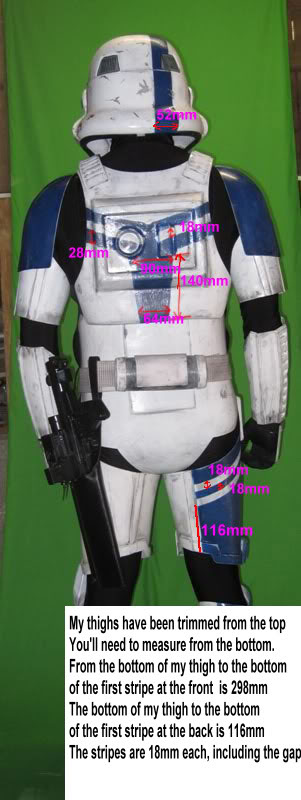
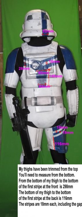
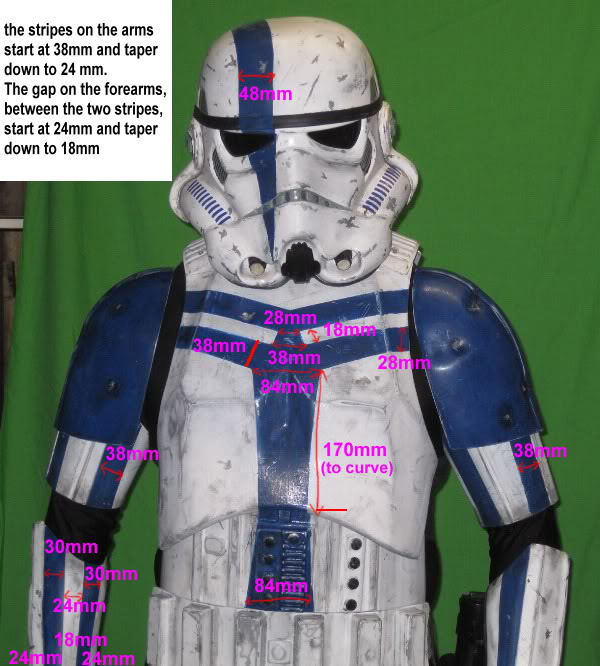
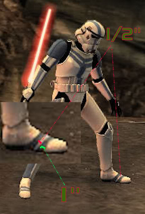
In preparation for my Centurion application I’ve been taking on board what’s been said on here during my EIB application.... thanks for the advice troopers [emoji3] Ok first job to get rid of my TD faux pas... remember the letters on the back of the TD... Anyway.... almost gone And totally disappeared [emoji3] I have also glued the drop box elastic to the belt to ensure they don’t move around I need to give the armour another polish , some new photos and then I think I’m set [emoji3] Sent from my iPhone using Tapatalk Pro1 point
-
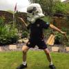
For me roughly its this: Kids get high fives and fist bumps, adults get the full Imperial treatment. There's exceptions but that's the gist of it. I've also acted as an interface to Lord Vader a few times with shy kids. They won't go near him, but a TK can bridge that gap and help reduce the fear of standing next to him for a photo, just make sure you know when to stop pushing, upsetting children is not what this is about.1 point
-
Like this: (Measure first!)1 point
-
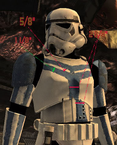
Cleaned up the vocoder paint, didn't take a before photo but here is half way through removing some of the Anovos paint: Here's after doing the other side and touching up the paint: Also re-did the right bicep han hook to get them to sit at the same height (not pictured).1 point
-
Coming along nicely and some great info fir others to follow1 point
-
Assembly - Part IV, Thermal Detonator The thermal detonator proved to be a tricky thing to get correct, but with a bit of patience, a lot of glue, and quite a bit of trimming, it finally came together. It is assembled in 5 pieces - the 2 end caps, the front and back sides of the tube section, and the kidney seam cover plate. 1) Trim the front and back of the tube sections until they nestle together. I installed the outer facing tube over the inner facing one on both the top and bottom as I found that it fit better together that way. Untitled by Taylor Goodson, on Flickr 2) I started at the bottom seam as it was easier to get magnets in there first due to the shape. Lots of glue once again to get a good strong hold. Untitled by Taylor Goodson, on Flickr 3) Once the bottom was holding itself together, I moved to the top. Here, I used a bit of extra glue at the seams to fill it out as much as possible. We will be filling all the seams later in the build, but beefing this area up a bit with some extra glue makes that process a little easier down the road. Note: before gluing this section closed permanently, make sure there is enough space at the ends of the tube to permit the end caps to slip in. Untitled by Taylor Goodson, on Flickr 4) Once the front and back parts are held together strongly, remove the clamps and magnets. The complete tube sits on the bottom of the long kidney covering plate. I found the center of the tube and lined that up with the center raised stripe on the kidney plate and made a mark to help with lining the components up while gluing. Then, glue the tube to the plate at the bottom (there is a flat rectangle printed at the bottom of the long plate in the KB kit, so it's quite easy to line things up properly). Untitled by Taylor Goodson, on Flickr 5) Finally, install the pair of end caps into the thermal detonator. The right cap should sit flush with the end of the tube while the left cap sticks out about and inch or so. I used E6000 for this step as the slower curing time allows for more adjustment to get the caps to sit just right. Untitled by Taylor Goodson, on Flickr Untitled by Taylor Goodson, on Flickr1 point
-
Cheers Stephen. [emoji51] Sent from my iPhone using Tapatalk1 point
-
Assembly - Part III, Torso Components Abdomen (part 2) With the abdomen boxes ready to go, it's time to connect them using some internal ABS and chicago screws. 1) The first thing to do here was the create a series of pieces to fill the gap between the abdomen box top and the abdomen itself. I found that a stack of 5 ABS scraps was enough to fill that space. Then, between the second and first layers of scrap, I installed the backs of two chicago screws. I drilled a pair of holes into the topmost layer to fit the chicago screws into. Then, I cut a notch out of each of the sides of the 2nd layer of ABS scrap to allow the back of the chicago screw to nestle between the layers. Untitled by Taylor Goodson, on Flickr Here is a shot from the side to show how the notches permit the fitment of the chicago screws. Untitled by Taylor Goodson, on Flickr 2) Glue the ABS stacks into the abdomen boxes. (Note: for the larger box (#3), I created a larger size interior bracket - still 5 layers thick in total, but wide enough to accommodate a total of 4 chicago screws instead of just 2) Untitled by Taylor Goodson, on Flickr 3) Line up the boxes with the abdomen itself and drill holes that match up with the chicago screw posts. Untitled by Taylor Goodson, on Flickr 4) Finally, install the screws into the matching posts to pull the boxes tightly against the abdomen as flush as possible. Untitled by Taylor Goodson, on Flickr The view from the interior: Untitled by Taylor Goodson, on Flickr1 point
-
It worked! Wow! Thanks again Darthanael for your frustration, trial and error. This is the kind of info one finds on this forum. My frustration was getting the best of me when I took the painter's tape off my gloves after I glued the hand guards with E6000 and they basically weren't attached at all. They just fell off. Then I tried Zap-A-Gap. Same thing. Then I searched the forum for 'attaching silicone hand guards' and stumbled upon Darthanael's build thread. You never know what little bit of information you post is going to really help someone complete their build. Keep posting everyone. Clenched fist. Silicone bends with my knuckles.1 point
-
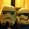
Made some discs to reinforce the inside of the helmet where the mic tips mount - boy is this some thin plastic, feels like a board game insert: Repainted the inside of the mic tips off-white to match the props: They were then given a clear coat of spray paint to seal them up. Afterwards I made another 'doohickey' for molding the mesh I received from Tony: Mic tip mesh was then installed (I put a bead of E6000 on the lips of the mic tips beforehand):1 point
-
I'm hella late to the party! Congratulations Sha Sha! Onward to Centurion!1 point
-
No Kit is approvable out of the box. But if build correctly, it can be 501st approved. As others mentioned, Anovos is known to have very long delays. You may be waiting over a year for your kit. There are many other armor makers to choose from. I suggest heading over here: Good Luck on your future build!1 point