Leaderboard

Popular Content
Showing content with the highest reputation on 05/24/2022 in Posts
-
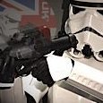
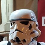
A few months ago, I got a set of Electrobinocs from @justjoseph63 and have been extremely pleased with them. But... well... I wanted them to DO something. I got the idea to turn them into Bluetooth speakers so they could play the TK Chatter or some music during non-blaster troops. And, fair warning, this is now a finished project. This won't be an ongoing build. I've wasn't even sure I could make this work, so I didn't post up a build thread for the binocs. I didn't wanna be defeated by this little hunk of plastic. This was my first step - hacking open the binocs. I sliced it at the rear intersection as it seemed like the most logical place. I then cut off the lens and drilled a hole in the (extremely thick) resin. Joseph doesn't mess around in the creation of these guys. The resin is VERY thick front and rear. Walls have some decent thickness too. It can face some serious action without being damaged. You know, aside from being hacked up. The front 3/4 is attached to the back eyepieces with 3 screws and a thick layer of glue all around. I used a dremel cutoff wheel to saw it free. I wanted to use the top knob as the volume control, so off it came. It was held in place by a small screw. I bought this little bluetooth amp off amazon... and destroyed it trying to modify the buttons to be remote. I would not suggest anyone get this amp if you want to modify it. I'm pretty good with electronics and regularly solder gauge clusters back together for my day job. Relocating knobs and switches bricked this little guy bad. Recovery wasn't possible. Then I happened across this Bluetooth speaker KIT on Parts Express. It was mentioned offhandedly in a youtube vid that didn't really have anything to do with the project. At the time of this writing, the kit is about $44USD. Check it out on Parts Express. I didn't need all of the parts, expecially the 2.5" speakers, but the kit was much cheaper than buying the parts individually. Separately, the board and wires are more expensive than the whole kit. I also bought the optional battery board and batteries to allow the board to play without being plugged in. A total of about $66USD. I used two of these tiny 1.5" speaker drivers (coincidentally also Dayton) as they juuuust fit into the binocs. If anyone out there decides to use these parts for their own project, I'd highly suggest buying an extra or two of the 2.1mm DC barrel jack. They're quite delicate and I had to buy a spare. One hole wasn't gonna cut it, so I printed a new sensor array in ABS and sliced off the molded one. Not a bad fit! And not a bad finish after a bit of extra sanding. The volume knob board required a very very thin wall to be installed into. So much grinding! And the speaker fit pretty well in the far left of the binoc housing, but not so well toward the right. More grinding. My dremel extension handle got some action. The tiny speakers needed to be stood away from the front holes to allow them to work well. My local Ace Hardware hand 1/4" spacers and associated tiny screws to enable mounting. I believe each of the speakers uses 3 screws to mount. Drilling tiny holes in a deep housing isn't the easiest thing. This extension made it possible. And let me just apologize right here for the severe lack of build progress photos I took. I had roadblocks at like every step of this project. The drill bit extension for example. Every time I hit a dead end and had to wait another week for more parts from amazon, I was uncertain if this thing would ever get finished... so I didn't take many in-progress photos. I think this pic was of the nose and sensor being glued on for the first time in about 2 months. I also placed speaker cloth in each with hot glue. One of the very few pix I took showing the inner parts placement. It's TIGHT in there. Speakers at the very front and just a tiny bit of space between the back of them and the front edge of those huge batteries. The batteries are screwed on in the very front and have some 50lb double sided mounting tape holding them in place in the back. The extra speaker wire and wire bundle for that volume knob are zip tied and stowed to the right side. The main Bluetooth board has barely enough space to be flipped and live right above the batteries. I used the top center button between the viewports as the power switch. The bottom two hide some screws. The bluetooth blue LED indicators light up the viewports. And the wires are indeed everywhere. I tried to tidy them before screwing the two halves together, but was only medium successful. All of the parts hide behind a printed acrylic panel. And here we are! That's a finished and re-assembled Electrobinoculars!!! It doesn't have the front lens anymore, but the opened up sensor array sorta makes up for that lack of magic. I really like the look of that sensor array. Non-cannon LED pilot light are pretty easy to overlook. The little green one comes on when the unit is charging. Red is power. The two things above the power & green LED are my original attempt at power and line in. They didn't go well. They're basically tiny speaker ports now. Power on and blue Bluetooth lights lit. Note the top button - it sticks out slightly and is a latching SPST push button switch. I found a 6mm switch that would fit inside the little button housing. The only downside of this button is that it can spin a bit when pressed. That's just the nature of the switch I used. It's installed tightly, just the button itself that can spin a little. This is VERY hard to see IRL, but it looks pretty cool in the photo. I did a holofoil desert scene with a little sandcrawler. At least it hides the wiring. And here it is!! A working demo vid. I can't wait to troop with it.5 points
-
Thanks, gents! I have 2 mannequins to build for my new man-cave, but after that I start on an F-11D. This really is a sickness, lol, but living in the middle of nowhere I have to keep myself occupied.2 points
-
Hi Chris, To allow post more and bigger photos to a post , you will need a Photo Host and add a link into the forum post you want. Mos of us use Imgur to store and post photos directly into the post. Take a read to the bellow tutorial.2 points
-
This might be worth a watch. :-)2 points
-
I ended up having to cut the corners after gluing cover strips down on several of my pieces. A straight razor blade works extremely well. It's small enough that you can't really apply a ton of force, so you can easily get the angles cut without harming (or sometimes even touching) the armor beneath.2 points
-
So here we go again. The first part is glued together: I´m just a bit confused on how to cut the the extra material on the back. I just want to say that I´m currently really busy so there will not be regular updates but I will still try do make progress.2 points
-
Our troops here are also exactly as Glen describes - VERY very few official LFL events and our garrison is not strict about such items. In the ~8 months that I've been trooping we've had one single LFL event that was limited to 5 troopers and I didn't volunteer for quickly enough. For official troops, we're expected to remove any and all non-canon items and wear our top spec gear. So, for example, the rubber gloves come out and the pilots gloves get put away. On all other local troops, we're encouraged to build and bring fun props like this that help engagement with the public. More than 50% of our local troops are non-blaster, which leaves us TKs empty handed. These binocs help fill those empty hands. One of our most popular troopers is a baby Yoda toy held by a Rebels Scout (people go crazy for Grogu here). Again, as I said, it's a laid back garrison. Others would probably not allow such props to be carried. Sorry if this project offended you Lluis.2 points
-
The trooper survival guide would.better explain the differences https://databank.501st.com/databank/TrooperSurvivalGuide2 points
-
You will find you will receive a lot of feedback if you post a build thread to our forum, lots of knowledgable builders ready to offer advice. As advised already check out some of the previous R1 build threads, a couple that stand out:1 point
-
Hi parker, glad to read you're starting your build and hope this thread can be helpful. My Front section is as yours, what I did was just trim the return edge a little more to allow more space to my head when suiting up. The reason I leave it as it was thinking about the plastic could weaken and break. What I would recommend is to leave it as it and If when finished your build you feel uncomfortable, you can trim it. " it's better and easier to remove plastic at the end , than add it again" Bellow is a sample photo as it's usually trimmed (not mine)1 point
-
Don't fret trooper. There are so many folks here and ready to help. You can do it.1 point
-
Those look awesome! Gotta love all those little extras that just add to a TK - always makes for fun interactions with the visitors1 point
-
Hi Nick, You’ll probably end up with something like this: If you have photos from a few feet back, that would be really useful to help with suggestions. :-) As you are aiming high, I thought I’d mention that almost all ANH coverstrips have small, 45° corners. I’ve put some examples below. Ideally, you’d cut these before you glue the cover-strips down.1 point
-
Looking good Nick. You can trim the cover strips following the two halves line or either straight More references1 point
-
Nicely done, sir!1 point
-
As I say it's entirely up to your garrison command, ultimately your GCO has the final say as to what they allow at local non canon events (who I may add can overule a GML), some garrisons aren't as strict as others. For canon events yes every accessory would need approval by the GML or GCO and be from that particular costumes CRL. Locally we have very few canon events but if we ever do only CRL approved accessories are allowed.1 point
-
WOW, Adam! And I thought I put a lot of work into building these, lol. You really took the ball and ran with it, sir, and I'm envious as all heck!1 point
-
Very nice, I have a printed version on my bench (never ending to do list) just waiting for some electronics, was going to add small screens behind the lenses with a video loop that can play a scene or zooming in or out, still haven't worked that part out.1 point
-
Of course you can do this, Chris!!! As Joseph says, don't try to rush. When in doubt, always ask before cutting or gluing (don't be afraid to ask lots of questions), and be sure to add photos(a picture is worth a thousand words) ...1 point
-
Wow ! Awesome as always Joseph!1 point
-
Awesome build; enjoyed following it1 point
-
Thanks for the forearm info. I have them trimmed and sanded and ready for cover strips. Just want to make sure they look ok before doing the strips. They fit fairly snug over my upper forearm, so I can’t trim down the raised areas under the cover strips anymore. Should I still go with a 15 mm cover strip or should I cover the raised area with a thicker cover strip? I removed the entire return edge on the wrist and most of it at the top.1 point
-
Finished! Again, please keep in mind that this 3D E-11 kit was apparently designed from the "Battlefront" videogame version so there are some significant differences. Most I could overcome, but a big one was the holes in the shroud. They simply do not correspond to the screen used (MGC) ones. I got as close as I could, so bear that in mind. Once I got ready to mount the U channels I found that my rivet gun was too wide to fit down into the channels themselves (pic 1). After a few choice curse words muttered under my breath I knew had to figure out how to attach them. I briefly considered screws, but it just wouldn't be the same. SO, I separated the rivets (14 of them), separated the mandrels (center parts), cut down the length and epoxied them back into the rivet pins as seen in the second 2 pics below. I should have mentioned before that when building the main body that I installed a thin metal tube inside the shroud to give the appearance of an actual barrel. Oops. My plan ended up as seen below (pic 1). Drill out the holes on the channels and shroud/barrel (just as one normally would) but I epoxied each modified rivet in. I was afraid this may make it sort of fragile, but after the epoxy set they are actually very sturdy. WHEW! HINT: Drill all holes in the channels and shroud BEFORE attaching them. The holes for the rivets were integrated into the print, but they did not line up correctly (mainly due to the barrel mods) so I drilled new ones. Hint: Make sure the holes for the rivets are between the holes in the shroud (pic 2). The channel that sits on the left side will have to have the bottom bent down on the front to accommodate the front "D" ring. HINT: Attach the D-ring/mount AFTER attaching the channels. The stock that came with the kit was too long after cutting down the length of the of the shroud earlier , and to add some "heft" I used a real vintage Sterling folding stock for this build, which differs slightly from the original- especially in the area seen with the red arrow (first pic). Not too noticeable, but I hope it doesn't keep me up at night thinking about it.** I did add the rivet on the side, which as I mentioned before will prevent the stock from extending. **It will. After touching up the paint and letting that dry overnight, I added some light weathering. Had these made for all my display pieces. And that's it. Finished, and finally added to my "wall-o'-weapons". To anyone who has followed this, thanks for looking! U-Channels- After spending more time that I care to admit to searching for these, I finally found a seller (George) on the RPF. Once he got them made shipping was fast and I honestly could not be more pleased with the quality. A little pricey, but well worth every cent in my opinion. Link to his sales thread on the RPF here. UPDATE: I did not realize that the seller was actually Caleb @TKCaleb who has been a member here since 2008. SO- it looks like you can contact him here as well!1 point
-
Here are some pics of where I plan to mount the bridges. Looks good to me, but please point out any concerns.1 point