Leaderboard


Popular Content
Showing content with the highest reputation on 08/11/2018 in all areas
-
Hi all, I'm Paul, I have been a member here for a while, but this is the first time I think I have contributed. Firstly I would like to say that the intention of this build is not to make a hyper realistic E-11 blaster, and I am aware more can be done in terms of detailing than I have done here to make a more accurate representation of an E-11. My goal was to make a reasonably accurate looking ANH E-11 which had the added benefit of an electronic light and sound system. Here is a video of the completed build which I did to talk about the build and demonstrate the electronics. I will start with a list of all the parts I have used and where they can be purchased. Doopy Doos Resin E-11 kit https://www.doopydoos.com/stormtrooper-e-11-complete-anh-e-11-blaster-kit-offer-2685-p.asp BlastFX electronic effects board & Mini Scope Display from TRamp. https://www.facebook.com/trooperamp/ Hegstler Counter box, Trigger assembly, Charging port assembly, & barrel LED mount from Lee McCormack - Shadow Defense Systems on Shapeways. https://www.shapeways.com/shops/shadow-defense-systems Power Cylinders from CSB Props on Shapeways. https://www.shapeways.com/product/ERH6MCTSC/power-cell-assembly-7-with-2-resistors?optionId=59449027&li=marketplace Hollow 1943 M38 scope kit from Bulldog Props. https://www.facebook.com/BulldogPropsJapan/ Various parts from Tino’s E-11 finishing kit including the scope rail and counter bracket. USB charging board. https://www.ebay.co.uk/itm/TP4056-5V-1A-Micro-USB-18650-Lithium-Battery-Charging-Board-Quality-1-2-5-10pc/163005239011?ssPageName=STRK%3AMEBIDX%3AIT&_trksid=p2060353.m2749.l2649 1000mAh Lithium Polymer battery. https://www.ebay.co.uk/itm/Conrad-Energy-Lithium-Polymer-Battery-3-7V-1000mAh-10C-with-BEC-Connector/122527159108?ssPageName=STRK%3AMEBIDX%3AIT&_trksid=p2060353.m2749.l2649 Black PVC tube, clear acrylic tube, & rare earth magnets. All purchased fro eBay. The only glue used throughout the build is Zap-A-Gap CA+ which I purchase from Amazon and Miliput was used as filler which can also be bought from Amazon. Spray paints are from Halfords, Clear coat and detailing paints are all Tamiya acrylics and Revell Aqua color, and the weathering washes are from the Mig range of model making products. My starting point for this build was the scope and mini scope display. I built the scope kit as per the instructions which come with the kit. I then drilled a 3mm hole in the underside of the scope just behind the front leg. The power cables for the mini scope display were then threaded trough this hole and the electronics boards slid into the body of the scope. I then used clear tape to secure the display to the red lens of the display kit, ensuring that the tape extended up the sides of the lens and making sure the display was centred on the lens. This was slid into the rear of the scope where the retaining ring inside the scope then presses against the tape securing everything in place. The clear lens from the kit the goes in on top of this and the scope lens retaining ring is screwed in to secure the whole assembly in place, making sure that the display is oriented correctly to the scope. Next I prepared the parts of the resin blaster kit. The counter box, scope, trigger and power cylinders from the kit were discarded as the would be replaced with alternative parts. The rest had any casting flashing removed, generally cleaned up and washed in soapy water. next I cut a hole in the receiver tube behind were the mag well casting will eventually be fitted. I marked the position of the mag well on the receiver and then marked out an area inside of this which still allowed for the mag well to be glued in place. the corners of the smaller area were then drilled out, and a Dremel with a router bit was used to create the opening. The receiver is actually quite thick as it has a PVC strengthening tube inside of the resin casting. I moved on to the trigger assembly next. A hole was created in the resin trigger group casting by drilling and routing with a Dremel once again. This hole houses the 3D printed trigger assembly, and needs to be snug, but not so tight as to restrict the trigger movement in any way. The trigger assembly was built up incorporating the trigger switch from the BlastFX unit. I opted at this point to cut the wires for the trigger switch in order to feed them through a small hole in the receiver, rather than having to make a larger hole to fit the switch itself through, which may need filling after assembly. I also fitted a small coil spring ( a cut down ball point pen spring) between the back of the trigger itself and the resin trigger group. This spring returns the trigger after it has been depressed. A hole was routed out in the back of the trigger group above the pistol grip where the rumble generator was fitted. Similarly the wires for the rumble generator were cut to accommodate easier wiring later on. Two 3mm holes were drill in the receiver for the 2 sets of wires to pass through, and then the trigger group was glued and screwed into place using Zap-A-Gap and self tapping screws. I chose the method of fixing as I want a very strong bond between the trigger group and receiver. The scope assembly was then fitted to the rail and counter bracket. The holes in the rail and counter bracket needed drilling out to take the screws which come with the scope. I ended up gluing these screws in place as the resin the scope is made from is quite soft, and I did not feel that the screws would hold for any length of time just by screwing them in. This assembly was then attached to the receiver in order to ascertain where the counter bracket would sit in order to place a 6mm hole behind it which would allow wiring access between the counter and the receiver. The scope and bracket were then removed and the front half of the counter was fixed to the bracket with some self tapping screws. A further 6mm hole was drilled through the bracket and counter to give access to the counter. I then cut a piece of 22mm diameter 3mm walled clear acrylic tube to length and slid it into the receiver until it sat where the barrel would normally be. The 3D printed LED end cap was assembled and the unit was then placed through the hole at the mag well, and placed over the end of the acrylic tube. The wires for the LED were once again cut to allow them to be routed back to the counter box. A length of 20mm black PVC tube was cut to fit inside the receiver to cover the charging handle slot so that the wiring in the receiver cannot be seen. This needs cutouts at each end to allow space for the wiring hole behind the counter bracket, and the charging board which sits at the end of the receiver behind the end cap. The Charging board and on/off/charge switch were assembled, and leads soldered on to reach back to the mag well opening. The main BlastFX board, display panel, speaker and selector switch where then all fitted into the 2 halves of the counter box, with the trigger, rumble unit and flash unit wires all fed out through the previously drilled 6mm hole. This hegstler box 3D print is a godsend if you are using the BlastFX system because it has been designed specifically for the components to all fit in. It has a cut out for the screen, a grill and mounting pegs for the speaker, and an assembly which creates the working reset switch, brilliant!!! As it is made for the BlastFX system though, it does have a 'BlastFX' logo where the Hengstler Eagle logo should be, so if that is important for you you may need to find a work around or alternative part. The corresponding ends of the cut leads were fed through the receiver and out of the 6mm hole behind the counter bracket. The cable ends were then rejoined by soldering them and heat shrink was used to cover them. Next the power lead from the main board was fed out of the back of the counter, and along with the power lead from the scope fed through the 6mm hole in the receiver and along to the mag well opening, where they were soldered to the appropriate leads from the battery connector and the charger/on/off switch. At this point the battery was attached and correct function of all the components confirmed, before the charger/switch assembly was glued into the back end of the receiver and all remaining cabling were fitted back into the receiver. I then effectively had a functioning blaster, except that the speaker was not working for some reason at this point. This was resolved shortly afterwards. The rest of the resin detail parts were then added. I also replaced the 2 screws at the muzzle with real metal knurled hex bolts. I also replaced the hex bolt in the end of the pistol grip with a real bolt too. Several other hex screws were used to replace resin cast parts. The end cap was fitted, and a section of foam was added inside. This foam pushes agains the end of the receiver and provides enough tension to hold the end cap securely in place so that it does not rattle around. The mag well and mag were hollowed out to allow the battery to sit inside. The mag well was then glued in place, and rare earth magnets were recessed into both the mag well and mag to keep the two together when the mag was inserted. The blaster was now ready for masking prior to paint. All parts to remain free from paint including the holes in the receiver which the clear tube can be seen through were masked off using masking tape and Blu Tak. The battery was removed. The front end of the scope was also removed to protect the front lens and preserve the metal finish of the screws which hold it in place. The blaster received 2 coats of Halfords grey plastic primer, which was allowed to cure for 24hrs. Then 2 coats of Halfords satin black were applied as a base colour. Once the black paint was touch dry I also added various bits of detail paint in Tamiya XF-16 flat aluminium, and X-31 titan gold. I also touched in any light spots in the black paint with Tamiya X-18 semi gloss black. I used a white wax crayon to highlight the lettering on the back of the scope. I also replaced all the parts I removed for painting, and unmasked enough to check that all the functions still work as they should (and they did this time). Next the blaster was dry brushed with the silver and the scope dry brushed with gold. This is to simulate ware and tear in the paint and finish on the gun. It is done by loading a small amount of paint onto an old paint brush (I find old and worn out ones work the best the more rough looking the better). Then most of the paint is brushed off. I use a folded piece of kitchen towel and just rub the brush on it until almost all the paint is gone, and the brush looks dry, hence dry brushing. Then just brush over the blaster and this will leave what little paint is left on any raised edges, corners and high spots which is generally where ware and tear occurs. Once the dry brushing has had enough time to dry, a wash of Mig ‘dark brown for green vehicles’ enamel wash was applied over the top of the dry brush weathering. This gives the blaster a more dirty look, and blends and softens the dry brushing a bit. When dry, this was then all sealed with a coat of Tamiya TS-80 flat clear. The clear coat seals in the weathering and gives the blaster a uniform finish. The final stages were to remove all the masking, and then hand paint areas inside the vent holes in the receiver which had missed paint due to the masking. I painted these is Revel Aqua Colour 08 black matt. The front of the hengstler box was given a very light brush coat of Tamiya x-18 semi gloss black, and the rear of the box was dry brushed in the same colour to try and give the look of the plastics used in the counters covers. There was then some very light dry brushing of the silver and gold paints again on areas where high levels of ware may occur just to bring out some of the highlights that had been dulled back by the earlier wash. And that completed the build. I would like to say a massive thanks to Paul Whitrow over at TRamp for his advice and encouragement, to Lee McCormack at Shadow Defence Systems for his excellent 3D printed parts which are superbly designed to just work with BlastFX, To Brian at BullDog Props for hid brilliant M38 scope kit and the advice on getting the right one for my needs, and to Tino for his fantastic detailing parts kit and scope rail. You all made this build a lot easier to pull off Guys thank you. Thanks for taking the time to read through this long post, I hope you enjoyed it. Paul3 points
-
That is really nice! Honestly that’s pretty close to what I would like to do. Who wants pristine battle armor? Sent from my iPhone using Tapatalk2 points
-
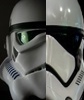
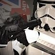
Pics Darker lens and s-trim installed More ear trimming. Baby steps. Compare pics after and before distressing the MP40 pouches. I used 220 and 600 grit sandpaper and a wire brush. Distressing small Spanish pouches. After and before. I roughed up the pauldron but the effect does not really show very well in photos, so I won’t show that. Pauldron after some black and brown paint washes. Boots got brown and dark grey washes. Everything got a few light coats of a dark grey/ sandy colour. I have pouches for both versions of the docking bay capt and cantina capt. Sent from my iPhone using Tapatalk2 points
-
No, a photo taken from wrist side looking through the forearm. Zoom out1 point
-
LOL Wish it would depend on me... Damn budget Enviado desde mi SM-G360F mediante Tapatalk1 point
-
That sounds like a plan Aunion1 point
-
Thanks for your kind words. Maybe I may add electronics in a future build, let's name my actual project Aunion 1.0/#1/Mk1 by the time being, if I get enough funds and wife permission we'll probably see Aunion 2.0/#2/Mk2. Cheers. Enviado desde mi SM-G360F mediante Tapatalk1 point
-
Great weathering1 point
-
Great job1 point
-
Thanks Aunion, I'm glad you like what I have done here. Of course another way of looking at it is that a scratch build is the perfect opportunity to include electronics as you can build parts around what is required to fit the electronics in. In some ways that would be much easier than adapting a kit. All the best with your build Paul1 point
-
I always find blaster electronics lots of fun. Beautiful piece of work, I've thought of including some in my build, but really think I do have enough scratchbuilding it from zero. Nice work. Enviado desde mi SM-G360F mediante Tapatalk1 point
-
Looks a lot better, Jim! It's entirely up to you, but I would also remove more of the return edge on the inside of the tops. The reason I mention this is that on a troop, you will be carrying your E-11 a lot (arms bent in) and that extra return edge can cut into you causing "armor bite" and doing that would make them more comfortable and increase your range of movement. It is also screen accurate. I noticed that you removed all the return edge on the top of the thighs. This is also screen accurate and something I always recommend to prevent chafing in your cod area. Nice job! Reference image1 point
-
No worries, Mark. Hehe - nothing like a set of armour to give us body shape targets. I'm heading towards a C-3PO build where you get bolted in!! Certainly a good incentive to watch what I eat!!1 point
-
Weathering the pouches and pauldron and boots. So I got a jump on the weekend - I took Friday off and spent quality time with my family - and by quality time I mean I snuck away every chance I had to work on my armour. I also installed a darker lens in the bucket, trimmed the ears a bit more (they can use even more to be screen accurate - yeesh), and installed the S-trim. Once again I made the opening of the helmet too small - my head fits, but barely. No head mounted microphone for me again. All that is left for the helmet is to install a bunch of Velcro and then add fans. I also heard from CrookKnight and my pack is ready for shipping. Woo hoo! All that is left is some sewing - still haven't convinced the wife to get that done for me. Oh, and I still need to add the t-track wires to my DLT-19 and build my T-21. But since it is 37°C (~99°F) here, I am relaxing with a very cold beer. I'll post some pics shortly. After a few sips of my very cold beer.1 point
-
The hight of the shins are as they should, I just posted on another thread you got that I would trim them but I ment circumference so we are clear on that If fitted correctly the shins will dig on the boot but not so much it can do any real damage, wear and tear is to be expected and in my opinion ads to the Stormtrooper-look. If you want you can protect them by adding soft velcro on the inside of the shins1 point
-
Just been having a play about with this, and discovered that this is the pattern projected on a wall from the flash when in stun mode. Reminds me of something????? I think this is very cool.1 point
-
Doing it in parts and peices,,, should be affordable and you can buy parts as you need them................1 point
-
You look very good! Joseph hit what I noticed. Only other thing... your belt is a bit long and that extra "flap" after the detonator might snag you on submission. I'd shorten up the belt a bit if you are able to, or hold down that extra bit with some velcro. Good luck!1 point
-
Thank you T-Jay, I really do appreciate the feed back, and it means a lot coming from you my friend. That was my thinking exactly regarding the detailing, just enough to look right. I think that even when you are just holding the blaster or have it holstered on a troop a good deal of the detail is hidden. If this was to be a 'wall hanger' where people could walk up to it and take in all the detail then yes I think it would be worth it. That said I will be hanging this on the wall I think but just as a way of storing it when its at home. I am sure that most people at troops will be more enthralled by the pew pew sound and light show this can put on than any amount of fine detail i might have put into it could inspire.... and kids will love it too I'm sure. Paul1 point
-
Nice going on that armor, sir! This should pretty much get you to basic level (depending on your GML), but since you did such a great job on this I am hoping to see your submission for EI and then Centurion! There are a few items that may or may not affect basic, but are easy fixes for the next levels. There are a few other tiny things for L2 and 3, but we can go into more detail at some point. The return edge at the top of your right forearm could use some trimming. The left one is good to go. Reference image The left drop box appears to have a strap that is too short, causing it to ride behind the belt (close-pic 2). This should be extended just a tad to match your right one (which is perfect). Reference image The right thigh could come up a bit to where it is level with the left. The sniper knee plate could be rotated toward the center, allowing the cover strips to line up. A piece of 1 x 1 x 10 inch foam inserted on the inside behind the inner cover strip works great to keep it in place. Reference image The bottom ear screw will need to be replace to match the ones at the top, (V shaped flat head). Reference image Overall a fantastic job, Jim, and once you are approved, don't forget to request your Legion access here: https://www.whitearmor.net/forum/topic/16-501st-trooper-status-requests-include-link-to-your-501st-profile-in-your-request/, which will insert the TK number you have worked so hard for beneath your name!1 point
-
Jeffery Rich 20980 EIB Letter Size Tony Thanks for doing this and feel free to add something about the First Ever Rogue One TK to Achieve EIB My apologies, Jeff, but the space will only allow me to put your name and TK #. However, it is listed under FISD Kudos right above your 2018 Supporter badge. Great work! http://www.whitearmor.net/eib/certificates/20980-eib.png1 point