

Scalawag
-
Posts
32 -
Joined
-
Last visited
-
Days Won
1
Content Type
Profiles
Forums
Gallery
Articles
Everything posted by Scalawag
-
Yeah it was good. We went on the Saturday, but it is a 2 day event if you want to do both days to make travel more worth while. A lot to see and participate in if that is your thing, but maybe a little pricey to get in. Jon Campling was there giving spell casting classes and all the usual, he was great as usual. I will most likely do both days next year, but then I only live 3 miles away I would say it is one of the better 'smaller' Cons I have been too, not an MCM or the like but fun none the less. I may see if I can get a more official invite next year for the group I belong to as well. Paul
-
I will be keeping my account here and look in from time to time Shanester, but probably contributing less. I am pleased this build will serve as one of the inspirations for your own DLT-19 build. By all means if you think I can help at all then just get in touch. Paul
-
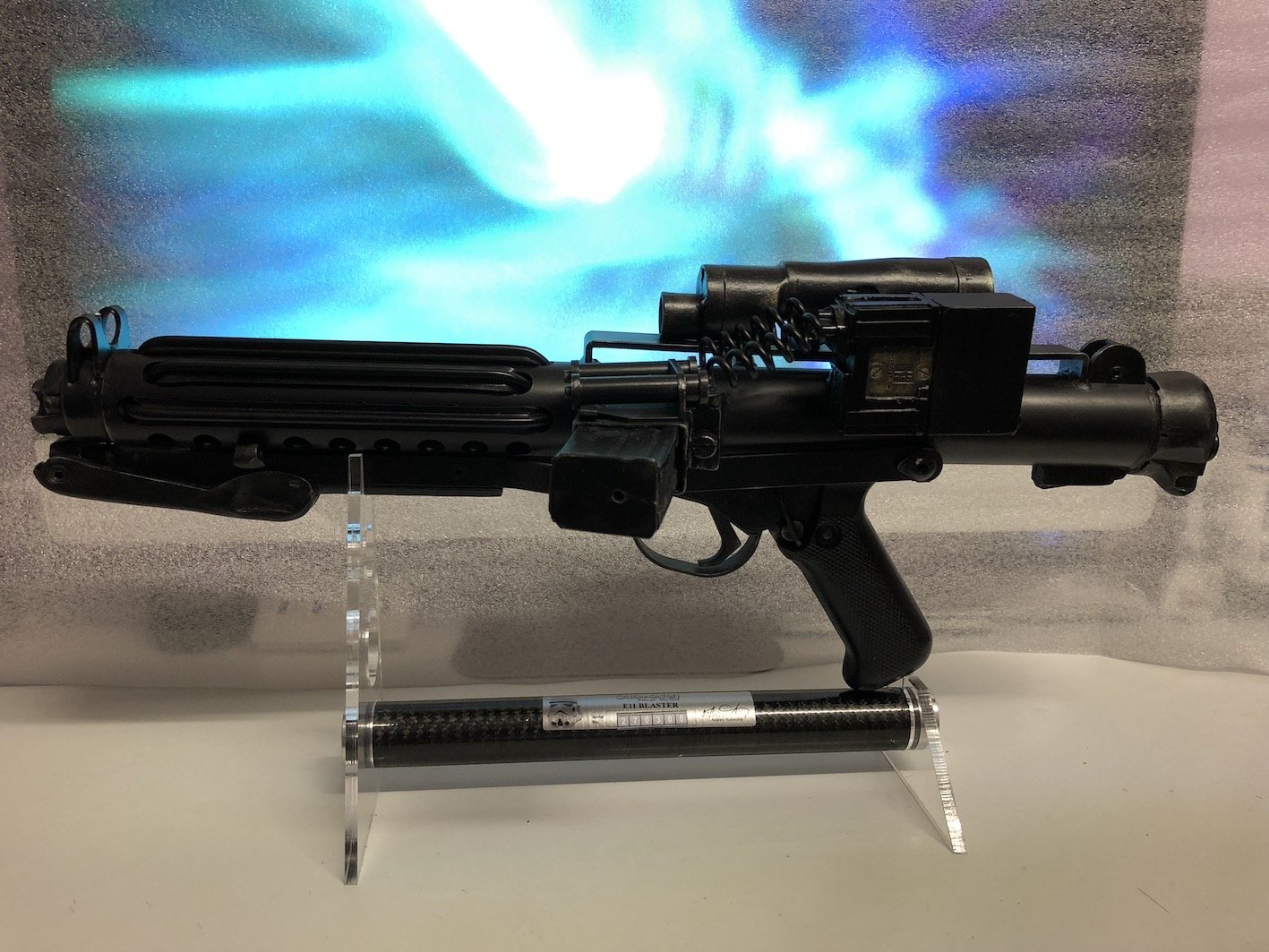
Thats great to know Coloursergeant, I'm glad I got the weathering to look so accurate. There is a lot more to my not wanting to take part here further than just the comments I have received here. I have had similar responses across most of the forums I have contributed to over time and many different hobbies. I suspect I am just to sensitive too it all if I am honest. I can appreciate that other cultures may communicate differently, but I also think that on an English speaking forum the onus should be on them to find out what English speakers might find offensive or rude, and not on the forum as a whole to just tolerate it. But like I said I am probably too sensitive for all this, and will now do most of my sharing about projects off line I am afraid. I took a look at your E-11 build, impressive, most impressive. Its a great build and a superb looking E-11 mate. Here is a link to my own E-11 build. Its a Doopy Doos kit with BlastFX electronics fitted. Paul
-

Coloursergeant's Steel E-11 Blaster Build
Scalawag replied to Coloursergeant's topic in Build Threads Requireing Maintenance
What a great build, I just popped over from my DLT-19 build where you left a link. This looks fantastic. The crinkle paint finish always fascinates me as the first time I saw a sterling with that finish was when I started to look at E-11 prop builds. I don't know how much you know about the finish and I hope I am not talking out of place here, but the crinkle finish is seen on 'export' versions of the sterling and so is very common outside the UK. All contracts for the sterling from outside the UK had the crinkle finish. However the UK military contracts all specified that sterlings should be finished in a smooth paint. Its the only difference between the UK military and export versions, other than this they are identical. In the UK we are far more used to seeing military surplus sterlings which all have the smooth finish which tends to wear more easily too. We hardly ever see the crinkle paint here, but occasionally we see a UK military sterling that has a crinkle painted shoulder stock, which I think is a result of the UK military buying parts from a canceled export contract some time in the early 1970s. They bought a load of internal parts and stocks as spares from the canceled export contract as sterling were anxious to make back some of the money they lost when the contract fell through. Interestingly the suppressed versions used by the UK military do have the crinkle paint finish. This is just my theory, but I suspect that Bapty & Co supplied ex British military Sterlings for use in Star Wars. It's impossible to prove of course, as records would not reflect this as they would not of noted this type of detail when the guns came into inventory with them, but it would make sense as the majority of Sterlings available on the UK market would be ex UK military spec ones, and buying export versions would have probably cost a lot more. Anyway, both finishes are accepted by the community, and the crinkle finish does add a more interesting look to the E-11. Not a patch on your build, but this is my Doopy Doos E-11 with BlastFX electronics which I thought you might like too. Paul -
Thank you for the kind comments and support chaps I appreciate it. Here are a couple of pics of the DLT-19 on its first deployment. These were taken at WynterCon, which is a con here in my home town of Eastbourne, UK. As you can see it takes place in a huge big top!! Whilst I am a member of 501st (Tusken Raider) I don't troop with 501st as a TK, so this troop was done as a member of the Imperial Outlanders (that's the badge on our pauldrons). I am working this set up into a 'clean' Heavy Weapons Trooper, so its still a work in progress, bits still to change and add. Its clean because then I can also troop the armour as a standard TK too. Paul
-
Thats fine I am not adverse to changing things again. As you can see from this whole build I do just that on a regular basis, but I will add that if you are going to make this sort of comment it would be nice if you also followed up your superior knowledge with with a bit of useful information for the recipient such as "but oh, here is were you can get the accurate stuff from". Or perhaps you just like to pick up on the things that are wrong with peoples hard work without actually having any intention of helping them along!! I am beginning to sense that this sort of semi helpful answer and lack of useful information is a bit of a theme within the 501st Legion. I am probably going to give up posting here now as I find the forum seems very quiet, and posts and answers are far too few and slow in coming. I could have done with this info a month ago!!! The curtness of some replies I have seen here I also find to be quite rude and inconsiderate of fellow members. Maybe we have forgotten how to be courteous in our replies to people since we all communicate through keyboards, or maybe I am just too sensitive and don't belong on the internet. Either way I am put off of contributing here further and I am not likely to now come back. Thanks Paul
-
I Just made a quick video documenting the recent extra detailing I have done on this DLT-19. All the bits used to detail it are linked to on the YouTube page.
-
OK so The disc greeblie I have been waiting for arrived this morning and is now painted and fitted. This was a difficult piece to track down and a big thanks must go out to Ian at Sandie Comms for supplying this: https://www.facebook.com/groups/240273392991782/?fref=mentions&__xts__[0]=68.ARDb_GWMz26ao7xzHKFon85QLM2pCsudnaUwjTO6PzEst4K_bpSIt-nhKR9x1PDmy8FYmWetJVb8wOAd6zm13efn-jEvAODOPNbXVvBNQi2I-0NY3wI5BH2MKq2SDbXHMLBacdKM9DFlbxlFmiAsFJZe6BVLIN12z_BG15b7FSrc41A4mO0kXQ&__tn__=K-R This now completes this build (well for now at least, who knows what I will find to change in the future!!), so here are some pics detailing the finished blaster rifle. Hope you like this and as always any feed back is welcome. Paul
-
More minor details added on my DLT-19. This time it is the two spring clips which sit under the barrel shroud on an MG34 that secure the Bipod and anti aircraft mounts etc. once they are in place. They are around 65mm long and made of spring steel on the originals, and secured to the barrel shroud with 2 machine screws for each spring. When fitting the bi-pod or other mount options these springs are depressed to allow the mounting ring of the bi-pod to pass over them. Once the bipod is in position these are released and spring back into place engaging with a cut out in the Bi-pod mount ring which then prevents the Bi-pod from being rotated back out of its mount. To demount the bi-pod you simply depress this clip again and the bi-pod is free to rotate. As these clips on both the mounting points were missing on my DLT-19 I fabricated some from the sheet metal I had left over from making the feed tray box. I used some spare screws I had lying around to secure them. They aren't spring steel, so they are less springy than the originals would be but they do spring a little due to their shape. The first 2 pics are the front mount spring below the front sight, and the second 2 the back mount at the opposite end of the barrel shroud. Minor details again I know, but I love all this stuff. Thanks Paul
-
A quick and minor update. The thinner aluminium sheet I ordered arrived today, so I have made up my Mk2 feed tray box for my DLT-19. I am happier with this version, as the folds look less radiuses and more like what I see in pictures of screen used items. It is once again just wedged into place over the feed tray as per the originals. Sprayed matt black, and then weathered by scratching of paint with a variety of implements. Thanks Paul
-
I have been doing a bit more work on my DLT-19. Still looking for a good facsimile of the disc greebie if anyone here knows of a good source for one. On to the latest changes. Firstly the nut I used as part of the bipod leg adjuster was annoying me. Its a minor detail, but one of those things that I saw every time I looked at the blaster, so I have filled in around the nut at the bottom of the adjusters frame with miliput so that the frame of the adjuster looks like one solid piece again. For comparison here is a before: And after: The thinner aluminium sheet has still not arrived so I have not been able to try that out yet, but I have added some finer weathering scratches and dings to the Mk1 feed tray cover. The red tinge in this one is actually my phone case reflecting off the bear aluminium. Paul
-
The Aluminium sheet that I bought to replace the feed tray cover on my DLT-19 arrived yesterday. I duly cut out the required pieces and formed them into the box shape using reference pics to judge the size this should be. I then painted the box matt black, and when the paint had dried I weathered the box by scraping off paint with an old plastic card. I had to cut a slot between the existing moulded feed tray box and the bottom edge of the feed mechanism. I decided looking at reference pics that I did not need to alter the size of the moulded box and the new metal one would be fine fitted over the top. The box simply wedges in place like the original did and needs no extra securing. Having done all of this though I am not completely happy with the end result. It's not bad at all, but I think that due to the thickness of the sheet I bought (0.8mm) the radius on the bent edges is too big, and needs to be sharper. To this end I have ordered some 0.4mm thick sheet aluminium to make a second box, and see if I can get the edges to look more how I want them too. Here are the pics of this first attempt box.
-
Thank you Shanester, I am pleased that you like what I have done with my DLT-19. I have a couple more upgrades to do, but it is coming along quite nicely so far. Paul
-
Thanks Chaps, glad you are liking what I am doing and the collection Right!! I didn't like how the first attempt at the additional T tracks on my DLT-19 looked, so I have redone it. This involved stripping off the track that came with the blaster, stripping the barrel shroud back to bare metal, repainting it, and fitting all of the new rubber T track. The new track is held in place with double sided tape, and then secured with the twisted wire fixings. I think this looks better as the T track is all consistently one kind. Because it is rubber the Track 'dents' under the wire as I seem to be able to see on pics of the original blasters. And of course the the positioning of the the tracks has been adjusted to what seems to be the accepted positions. Paul
-
The extra T track for my DLT-19 blaster arrived today. I decided to leave the original T track in place even though the most accepted positioning of the centre 2 pieces on the rear section should be at the 9 o'clock & 3 o'clock positions and mine are lower than this. Actually looking at the very few pictures of the original DLT-19s I can find it is not entirely clear what the positioning is. And as at least 4 were made for ANH so I am claiming a little artistic license here as the pre applied track is glued in place and will take off a substantial amount of the paintwork if removed. I have also added the wire which was used on the originals to hold the tracks in place. I used 15amp fuse wire for this, which was painted black after it was applied. Once again pictures of original pieces are unclear and grainy and it is difficult as a result to accurately accertain as to how this wire was applied. My best guess from looking at the reference pics is that it was wrapped around the rubber t track just behind where the slopes on the ends are around the full height of the track. There are some very clear pics of an excellent replica DLT-19 that show the wire at the ends of the T track though the centre of the slopes at the ends, which I believe has been copied extensively, but to my eye this positioning of the wire is not what I see in the pics of the originals. I chose to slot the T track on mine, as some of it is hard plastic and would not 'dent' like the rubber stuff. I know it is probably not 100% 'accurate', but I think it is very close, and in any case as I have already mentioned in my opinion, some of what is accepted as 'accurate' may not have that much clear evidence to support it anyway, and be a result of the only clear pictures of DLT-19's being those of replicas.
-
I have been asked, both here and elsewhere about the details of this DLT-19, and so I have made a video which shows the blaster, how it functions and breaks down for transport etc.
-
ANH - Blaster on the left hand or right hand?
Scalawag replied to Ripper_L's topic in General Weapons Discussion
I remember seeing an interview with Roger Christian who put together a lot of the weaponry for ANH including the E-11. He says in the interview that they had to make the holsters left handed, and that a lot of the troopers carried the E-11 left handed because of the magazine sticking out of the left side of the gun. He did not realise that using the Sterling for the E-11 would have this effect as he is left handed and it only became apparent to him when the actors started using them. -
My DLT-19 is now on display on the wall of my lounge. Quite appropriately the 1/6 scale Afrika Korps diorama beneath the DLT-19 includes 2 MG34s, one on the sidecar, and one on a Lafette tripod mount, as well as my 1/6 scale 4-LOM in my bounty hunter collection having his DLT-19 of course.
-
Thank you Tig70, and I am glad you like my work on this blaster. It is an exceptionally good replica to begin with, and a little TLC really brings it to its best in my opinion. I may get round to making the alterations at some point in the future, but for now I am pleased with the overall look of the finished article. Thanks again Paul
-
Thank you Shanester, I am glad you like this. The bipod on this is a fully functional copy of the MG34 bipod. However, as it is supplied it does need a couple of things doing to it. Firstly the screw situated between the bi pods legs adjusts the width of the legs, but the original piece is made from resin and not very strong, so I would advise replacing it. I replaced this on mine with a nut and bolt of similar size which I already had in my spares. I cut the nut into the adjusters frame to provide a set of metal threads rather than rely on the threads in the resin frame itself. I then also cut off the resin threads from the original screw, drilled a hole the size of the new bolt head in the remaining part of the screw and glued the bolt I had into the hole where the original threads had been. So now this adjuster is operated in exactly the same way, but has more robustness to it as it is running on metal threads. The only visual difference is the nut visible in the bottom of the frame, but that could easily be filled in with Miliput or some similar filler. You can best see the nut cut into the bottom of the adjuster frame and the new threaded bolt of the screw in this pic. I also added 2 springs to the legs, which push the legs open when they are not latched. I don't know if the original had this or not but it does have a couple of advantages. Firstly when the bipod is deployed the legs are always in the open position which is what you often see in pics when the bi-pod is not in the stowed position. When the bi-pod is stowed the spring pressure helps the latching system to stay in the closed position. It can be a bit sloppy and rattly without the pressure from the springs I added. Whilst the Bi-pod is a great replica it is made from resin, and so may be a bit fragile for any form of frequent or heavy use. The loops where the latch engages with the legs are I would say particularly fragile. This is such a good replica that I suspect a real MG34 bipod would just fit in place, but obviously adding all that metal to the font end would affect the balance of the blaster. I hope this helps with your question, and once again thank you for the appreciation of my work. Paul
-
I have reached that point with my DLT-19 where it is wise to stop and call it done, rather than carrying on and risk overdoing things or ruining the look. So here it is finished. This is a Resin cast with a an alluminium barrel shroud produced by ProCoPrint3D: https://www.pcp3d.com It has many moving parts and being cast from moulds taken from a real MG34 it is accurate in many respects, and disassembles for transport just like the real gun. It has many moving parts, and I think looks very good with a minimum of work. I have described earlier in this thread the preparation and painting of this so will not go over the specifics again except to say that I have now added some weathering to the feed gate box and round greeblie on the pistol grip. It appears that these were both made from Aluminium and as such look a different colour when scratched than the steel of the gun itself. I have tried to replicate this using Tamiya XF-16 flat aluminium but this time without the dark wash over the top. I have included the pic I used for reference for these pieces along with the other pics of my blaster. I have included several detail pics so that you can see some of the finer parts of the casting etc... I have deliberately kept the weathering subtle for this blaster. I don't like things that look 'too' weathered, and I hope I have achieved a good balance here of showing wear and tear without looking completely beaten up or not realistic. There are some elements which I am aware are not strictly accurate. The T tracks should be placed slightly differently and there should be a few more of them, they are also glued in place rather than being held with wire. The box in the loading gate is the wrong shape and size, and the round greeblie on the pistol grip is slightly too small and again a slightly different shape. These are all small areas of difference which I may change at later date but for now I don't think they detract too much if at all from the overall appearance of the blaster. There is some miss moulding on one of the bi-pod legs, but Christopher at ProCoPrint3D has kindly sent out a replacement for me which will be substituted when it arrives. I am very pleased with this blaster, and I am very happy with the end results I have been able to achieve with it. I think it makes a very realistic version of the DLT-19 Heavy Blaster Rifle.
-
Yesterday I took delivery of a new DLT-19 from ProCoPrint3D. This is a resin casting with an aluminium barrel shroud. It is cast from moulds taken of a genuine WWII vintage MG34. The casts are very crisp and even have some very nice WWII MG34 markings on them (even on the separate barrel), and because it is cast from a real MG34 it assembles pretty much as a real MG34 would do, and can be broken down easily for transporting. There are several moving parts including trigger, cocking handle, front and rear sights, quick change barrel assembly (with separate barrel) and removable stock. I am aware that the layout of the T tracks is not strictly correct, and I may well alter that in the future. I did have an issue with a badly cast Bi-pod leg, but ProCoPrint3D have corrected this for me quickly and sent out a replacement by return. I have for now made some repairs to the poor casting with plasticard and Miliput putty to get the project up and running, but I will replace the leg with the new one when it arrives. This is the DLT-19 as it arrived from ProCoPrint3D, after assembly though of course. Today I cleaned up the casting a little bit and added the round greeblie on the upper left side of the pistol grip using a cut down ballcock washer with a hole drilled in its centre. After this I laid down the base colours which are largely Halfords Satin Black, with Vauxhall Steel Grey, also from Halfords, being used for the barrel. Normally I would apply primer before painting, but this blaster came painted a semi gloss black, and so I simply rubbed this down and used that as a base for my colours rather than a separate primer coat. Here are a couple of pics showing the nice markings to be found on this blaster. Once the base colours had had a suitable amount of time to cure I then dry brushed the entire gun apart from the stock and pistol grip in Tamiya XF-16 Flat Aluminium. This is to add a look of ware and tare on the blaster, although I have to say it is really hard to find a really beat up looking MG34. They are made to a very high standard and even after 70 years many retain a lot of their original finish and still look to be in very good condition. I always look at pictures of the real gun to ascertain where ware may occur, and the colours etc. that the ware causes. This is some of the parts after the dry brushing. The next step was to add an all over wash (again missing out the stock and pistol grip) of Mig Dark Brown Wash for Green Vehicles. This adds to the patina on the blaster and helps to tone down the dry brushing a little. Here are the parts drying outside after the wash has been applied. Once the wash had dried sufficiently all the parts were given 2 coats of Tamiya TS-20 Flat Clear spray, allowing 15 mins between coats for the clear coat to dry. This seals in the weathering and protects the paintwork a little, as well as helping to prevent the paint and weathering from wearing off and leaving black/dark marks on lighter surfaces. That is as far as I have gotten with this today. Tomorrow I will redo the dry brushing in some areas just to emphasise a little bit the ware in those places, and I think I will be pretty much done then. Thanks for reading this far. I will post more pics as progress continues. Paul
-
Doopy Doos E-11 with BlastFX electronics. (complete build)
Scalawag replied to Scalawag's topic in ANH BlasTech E11
thank you Mupfel, I am glad you like it. Paul -
Doopy Doos E-11 with BlastFX electronics. (complete build)
Scalawag replied to Scalawag's topic in ANH BlasTech E11
A very minor update. I did some more reading up on the Hengstler 400 counter boxes that were used on E-11s in ANH. I gather the ones with the 'eagle' logo predate WWII as the Hengstler company changed the Eagle logo in the late 1930's to avoid any association with the Nazi party. Interesting stuff, but anyway, the front end of these seems to have been made of some kind of high grade cast white metal, with most being plated in cadmium which gives them that sort of brass like finish we often see in pictures of vintage counters. The cadmium was there to prevent oxidisation I think. The rear cover of the boxes are usually a light grey coloured hard plastic of some kind. The prop department for ANH painted them black for the film, and so I have tried to represent these original finishes in places like corners where the prop departments paint may have worn off. The front of the box has been dry brushed on corners and edges with Tamiya X-31 Titan Gold to try and replicate glimpses of the cadmium plating. It has come out more a silver colour in the pics I have taken though so you will have to take my word for it that it is a more brass sort of colour in reality. The back cover was similarly dry brushed on the corners and edges where paint may get rubbed off, this time using Tamiya XF-19 Sky Grey to represent the original light grey plastic used. The last detail addition is the 2 electrical connections at the front of the box. These I gather are not seen on all Hengstler 400 counters and they are I believe a removable part. The connectors seen here have been fabricated from plasticard, painted with Tamiya XF-16 Flat Aluminium, and then given a dark enamel wash to tone them into the rest of the paintwork. I am not sure if I actually like these yet or not, and so they are not fixed in place, but have enough friction to hold them in place anyway. Paul -
Doopy Doos E-11 with BlastFX electronics. (complete build)
Scalawag replied to Scalawag's topic in ANH BlasTech E11
That sounds like a plan Aunion
