Leaderboard


Popular Content
Showing content with the highest reputation on 09/13/2017 in Posts
-
In-coming....another WIP update: Inner bolt clearing strip I went and studied the correct location of the clearing strip on the inner bold with FISD E-11 Blaster Reference as my primary source. I then etched in the location using a pencil and measured out the width of the strip along with the approximate length of the strip. The width measured 6mm and the length measured approximately 50mm. I then followed these dimensions and cut to shape on a 1mm thick plastic piece using my lexan scissors. I then proceeded to go at trimming the ends of the cut clearing strip. It was a bit tricky trying to gauge where to cut, especially when putting it against the curved inner bolt. After eye-balling it the best I could, the ends were cut and then I proceeded to shaping it. I heated the strip using my heat gun. At high setting, the 1mm thick plastic became pretty maleable, pretty quickly so I pushed it against the inner bolt over the templated part of it. I used the middle portion of my long nose pliers to push down on the strip. After some trial and error, I did manage to twist the strip to form along that part of the inner bolt. Here, I go about gluing the clearing strip to the inner bolt. I created a glue applicator using a piece of armature wire and used a piece of this kind of wire to rough up the glue-side of the strip to prepare it for adhesion. The CA of choice is E-6000. I figured using it would give me more know-how when I do use it to build my TK armor in the future. With the clearing strip glued in place, I used a clamp to keep things together for the curing process. Also, I felt I needed to use the popsicle stick method to fill the void between the outer receiver tube and the top of the clearing strip. Here is the clearing strip as it should be after gluing. I will check in 24 hours how it dried. Thank you once again for reading, cheers!! Jesse4 points
-
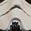
Hiya. A bit more work this eve. Tidied up the holes on the underside using a 9/10mm (approx) Dremel sander. Still some final tidying to do, including the different shaped one where the folding stock would mount. Also removed the fake bolts from the folding stock and replaced with carriage bolts (not solidly fitted yet). As I don't have a precise measure for circular objects, I decided to use an adjustable spanner, measure the outside of the object, then measure the spanner gap. Cheers, Dan :-) Sent from my iPhone using Tapatalk3 points
-
This picture says it all! My SBB in all it's glory! Wooh, it was a good month of waiting which isn't so bad at all considering it came from the UK. For my E-11 Blaster, I decided to go with a Doopydoos Full Resin Kit. All parts were delivered but the folding stock - wishbone had a piece broken off. This is my first blaster build. First time also working with Resin. I am going for good level of screen accuracy, battle worn and as realistic as possible, especially as it pertains to the SMG part. I will be making a ANH version of the E-11. To bring the blaster to the next level, I am complimenting the doopydoos kit with T-jay's Completion set, and Chris's 3D printed parts. Although originally looking to get Steve's magazine replica some time in the future as well, it will be a toss between it and Robert's magazine, as the latter is hollow and I may need room to put electronics. One huge addition I am absolutely to-the-moon-and-back about is installing Paul's fully wired and ready to install BlastFX - electronics that will bring the E-11 Blaster alive with lights and sound. This latter addition will be a dream come true; order made to arrive late October 2017. As for instructions, I am relying heavily on the E-11 Blaster Reference Manual. Thank you thank you for all the authors involved in this valuable document - gives us newbies a solid step forward. My timeline for completing the blaster is likely a year or so into the future. I am just out to revel at every detail, enjoying small advances every day. With E-6000 as my CA of choice and allowing for green stuff to fix mistakes with that cure time of also, 24 hours, I need all the time in the world anyways. Also, I'm not going on any particular order. Generally speaking, I will be putting the SMG portion together first then, move to the E-11 parts following, but not in every case necessarily. Also, I will seemingly leave component parts 'incomplete' and jump to another component part. So in short, my build will not be done in orderly fashion. Well, without any further due, let's begin!!! After a nice wash to get rid of fine resin dust and left over release agent chemicals, I proceeded to sand down the two ends of the broken part to get ready for applying the reinforced epoxy. I then placed the entire folding stock / wishbone piece on my vise. I placed Popsicle sticks to fill the void between two forks of the wishbone and held them together with tape. After having the epoxy settle while the piece was on an angle sitting on my vise, I felt the epoxy was starting to harden, although really, it was just a short while, so I positioned the piece vertically, so to use gravity for better surface area contact between the resin parts and the epoxy. After cure, all is well! The forks sit evenly between themselves - Yes! Just need a little sanding down of the left over epoxy around the seams which I'll do later when I tackle that piece. Here, I drill all holes in the Receiver tube. Before getting into details, want to emphasize how fine the resin gets when you're killing it. Highly recommend, as it was highly recommended to me, to use a proper respirator and safety glasses. Nothing beats safety and ensuring for good health! So I began by measuring out the existing holes made by Doopydoos using my precision measuring tool and came out with 7 / 16 " and was delighted to see a matching step on my step drill - bingo! I then used my kids crayola crayon to mark the center of the to-be-cut holes and placed the receiver tube on my vise trying to keep it as horizontal as possible, trying to eliminate any tipping and rolling etc. As for the drilling, I tried to keep it as vertical as possible and let the drill do it's work. It took a while, especially when you hit the inner metal tube. I was afraid to go too far so, as you can see, I didn't go all the way to the 7 / 16 " mark, afraid I would over-rotate and make a large gaping hole! It was difficult to see how far I drilled too with all that swiggly resin coming about from the drill process. I will need to go back with some fine precision to get it just right. Better to proceed with caution right?, then have nothing to work with and sorrow. I will need also to finish drilling the rest of the holes, which, hopefully, I will be brave enough to commit to the 7 / 16 " mark more firmly. Here is finer detail showing the work more clearly. I am happy to have made it this far though as I try to be as systematic as possible, wanting to have a clean build with as few mishaps as possible. I proceed with finishing off drilling the remaining holes of the receiver tube. After marking the center of the holes, I created pilot holes and proceeded with using the step drill bit this time around. This just gave the step drill more grab and helped me have my holes more aligned. If you noticed, my first set of drilled holes had one that was pretty off! Here's the piece after drilling. As you can see, I still have the folding stock notch that still needs to be cut out. Oh and yeah, I went a little trigger happy with my drill and tackled the holes on the underbelly of my wishbone. I also will need to do some modeling with 'green stuff' to fill out the handle piece I mangled. This complicates things for this piece, especially about the extension tube which I destroyed, but I will get around to addressing these later. I picked up a 6 in. Round Bastard File (the weirdest of names) to help sand down the uneven inner parts of the drilled holes. While sanding, I noticed that Doopydoos leaves allot of resin where the T-tracks meet / grab onto the receiver tube. The holes on either end of the tracks are filled with excess resin which obscures and takes away the kind of detail I want. To open up the T-track grab holes, I first drilled... ... and then used, what's called a Riffler file to get at shaping out the hole. I learn something new everyday. It says they are made for woodworking, but it is working fine so far. They're pretty tiny tools that come in many sculpting forms. The one I chose is curved on the outside and cornered on the inside. I am hoping the curvature will help me shape the hole and the cornered part of the file to give me the angle I want for shaping the T-track part. Here's the cornered part of the Riffler file tool I just mentioned. Here's the tool getting at the T-track part... ...and now the hole curvature part. Here's the T-track grab hole the way I want it. I think the cut out / file will get cleaner as I work the other holes. The vent hole notch is now cut out and I've managed to patch-up a vent hole that was quite off. Hollowing out the folding stock was quite a bit of work as you will see. Receiver Vent Hole Notch Precision measured the notch to be 3/16" and applied a 1/8" router bit to my Dremel 3000 and put it to task. Followed up by using a square file to get it clean. Redo of Vent Hole Used a 7/16" thread-cutting tap to carve out a portion of the vent hole. Then proceeded to fill entire hole with green stuff. I let the green stuff harden over 10-12 hours to be safe. Then I drilled through once again and followed through with a sanding file. Now, the vent hole is the right size and in the right place, mostly - it's now to my liking. Hollow out Folding Stock Used 1/4" 60 Grit Sanding Band (Dremel 430) at medium then high speeds, ranging from 30,000 to 35,000 RPMs. Before I knew it, resin dust was spewing into the air. SO glad I have a good quality respirator because there was a lot of resin dust by the end of the task. My little nylon brush came in really handy to brush away dust between sanding sessions. I managed to hollow it out in about 1/2 hour. I will need to go back to lightly sand to get it just right. Finally set-up my workshop - here's my set-up for resin work for use of my dremel and for manual handheld sanding. Progress on front sight. I precision measured a dimension on the block and compared that measurement with the real sterling dimension from the E-11 Blaster Reference guide. They don't match up. I gather, generally speaking, doopydoos somehow reduced the scale of the thing? Think will likely need to eye-ball it to get it to proper shape. I came away quite literally, 'short' on trying to make due with my Doopydoos front sight block. Having filed it to shape it,it came out really small! Don't think any pin is going to fit inside let alone a grub screw! Order for Chris's 3D printed part happened real soon after this! In this test-fit pic, the block does look reasonably well but definitely, still on the small side. I did do good on texturing the appropriate parts of my front sight though, like that of the original sterling - green stuff applied and patterned. Green stuff applied Knurling pattern source Pattern applied Pattern applied to back I then removed the strip on the bolt and also made that part of the receiver tube more pronounced. Doopy's resin blobs for screws were also removed. Strip removed Edge enhanced Resin blobs for screws Left blob removed Right blob removed Proceeded to hollow out the outer edges of the bolt, I've gone and recreated the plunger and extractor. I'm happy with it mostly, although still lacking in size and detail but I like it enough to move on. When my completion kit arrives, I have to follow through with putting in the strip that diagonally runs across it. As I don't have a letter and number stamp set to put in the serial number thingy on the bolt, that will be a much later addition. Plunger & Extractor Did more detail on the folding stock. Having hollowed where the rod sits a while back, today, spent the time to add realism to the piece. Carved in and around individual pieces that make up the folding stock to add realism by making it look more like movable parts. There's a ton of 'green stuff' where I was too generous using the Dremel. Still need to follow-up to sand those parts down. Folding Stock I was careful not to hollow out too much of the opening so to reveal the latch inside. Proceeded to work on magazine power cylinders. I just took out the central capacitors with my dremel. Original power cylinder Close up of central capacitors Central capacitors removed I proceeded to tackle a rather significant component of the E-11 Blaster - the m38 scope. I've managed to use spade bits to hollow it out and made some front and end cuts. I've purchased a monocular and will place it in the inside. With the scope being hollowed, I'm hoping the light coming through to the inside will make the monocular functional. Lenses will be placed on either end of the scope as well - with it's concave shape, this will help with drawing light in. A third glass-like disc will also be placed near the large lens end of the scope to reveal graticulars, cross-hair thingys, you know, for aiming at those rebel scum! Original m38 scope - front assembly end Original m38 scope - large lens end I uses spade bits to get the job done. 1" (25mm) bit was used to begin hollowing at the large lens end. 3/8" (10mm) bit was used to begin hollowing at the front assembly end. I tried to be as tactful as I could to progressively move to smaller bits as I proceeded deeper into the scope from the large lens end as you need to take into consideration the narrower contours as you get further in. If you do make a mistake as I did, not tapering in far enough, it's nothing green stuff can't fix. Hacksawing to remove large lens housing Front assembly end - lens housing removed large lens end - lens housing removed Reassembled scope - front assembly view Reassembled scope - large lens view I was eager to get started as ordered items from Shapeways arrived in the mail recently. I now have a true replica of the sight block and pin. With this piece in my possession, I proceeded cautiously to carve out a 'dove tail' channel that will hold the sight block. Having cut-guides put in place, I proceeded to cut out the channel using a hacksaw blade, and using a square and mostly a triangle file to get it to shape. I dare not use a dremel or I would have messed this up really bad. Applying intricate filing and allot of patience paid off. Although the block sits a little loose on the channel than desired, it's nothing green stuff can't fix. I'm overall quite happy with the results. Sight block position template Outline of template Template removed Precision measure for depth of dove tail channel Hack sawing is the first go Square file to retain hard edges at 90 degrees Masked hard edges so I don't widden top edge of dove channel Finished dove tail channel Top view of finished dove tail channel Side view of finished dove tail channel Sight block with pin, test fit on finished dove tail channel Side view of front sight installed Thanks for reading! Any and all comments welcomed.1 point
-
Hi. I have recently acquired my EIB and just got round to sorting my updated photos. I have made the changes adjustments asked for and am looking to get Centurion status in my own armour Name: Ross Walmsley 501st ID: TK5509 501st Profile: https://www.501st.com/forum/memberlist.php?mode=viewprofile&u=5659 FISD Forum Name: Ross8008 Garrison: UK Garrison EIB thread link.... Armour: RWA Helmet: RWA Blaster: Sheartech rubber Height: 5' 10" Weight: 12 stone 6 lb Boots: ISD Canvas Belt: RWA Hand Plates: ISD rubber Gloves: ISD Latex hand guards Neck Seal: RWA Holster: ISD Undersuit: Extreme 2 part Electronics: trAMP let me know if you require any more Photos, cheers Ross1 point
-
Now that's more like it. A quick sanding and can swap did the trick. Just a little more progress chipped off the mountain. Sent from my Pixel XL using Tapatalk1 point
-
Cheers buddy. Recommendations from you guys are everything. Sent from my Wileyfox Storm using Tapatalk1 point
-
Paul will answer any and every question you may have about his modules, and do so in record speed. I've recently purchased one for October delivery - looking forward.1 point
-
Looking good Ross, sure to be a pass!1 point
-
Thank you . here is the photo of the wrist end of the forearms showing no return edge... cheers Ross.1 point
-
Congrats and well done Matt!1 point
-
Wow! Thanks for all the hints and tips. I will get to work on this all ASAP!1 point
-
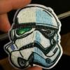
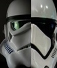
Asking for lid pics is like asking to see someone's baby pics - how could anyone refuse such a request! Here's a few of pics of the preassembled and finished helmet that came with the original full armor kit which I modified. I haven't worked on the separate helmet kit I later bought and received last month. Out of the box and my first mods (trim eyes, lift brow, remove teeth paint and repaint 4 per side with brush): Later, add brush painting of 5th tooth for each side (current state):1 point
-
We are getting very close now guys ,we attached all of the parts we modeled and printed for the lower portion We have a few more parts to add and also the feed tray cover . Stay tuned Sent from my iPhone using Tapatalk1 point
-
Great progress Dan [emoji106] awesome!1 point
-
Congratulations and welcome to the ranks trooper1 point
-
Hey Matt thanks for your patience and thank you for your EIB application. Let's take a look. CRL and EIB Application Requirements: As mentioned by Joseph nice work on those kidney shims. Looks like all the required submission photos have been posted. Andrew and myself are pleased to announce you armor displays all the necessary components to qualify you for Expert Infantry. Congratulations Other-Armor Fit/Assembly: As you know as we get to the higher levels of accuracy we look a little deeper. In this section we'll review observations made by either your fellow troopers or Andrew and myself. Some observations may lead to suggestions to improve the overall look of your armor. If any suggestion affects any application, it will be listed separately in the above or below sections. We have a few minor areas we'd like to mention, starting with the helmet, great job BTW. It appears the left side tube stripes are wider than the right. This could be a photo issue, if not you might want to trim the outer edge. Reference photo Moving down, the shoulder bells should be tight against the chest and back with little gap. We're suggesting you tighten the upper strap and maybe remove the lower return edge to bring it closer also. Reference photo Next up there should be very minimal gap between the kidney and back and posterior plates. This could be a simple strapping adjustment. Reference photo TD off center. Obviously a photo issue and easy fix. When you get a moment please remove the MFG pipe details. Though no one will really see it's not screen accurate, or canon. Reference photo And finally we noticed your sniper knee was resting against your leg in the photos. We're suggesting you trim this back quite a bit increasing the space and prevent armor damage, or better yet bodily harm lol. Reference photos Centurion Suggestions: And in this section we prepare you for Centurion. The only areas of concern here is keep in mind at Centurion there's to be little to no gap between the Ab and Kidney. You're possibly over the required gap limitation for this area. A simple strap adjustment should do the trick. Reference photos That's it. Again, very nice work on your build and hope to see you at Centurion.1 point
-
There was less attention to continuity in those days. People generally only saw a film once and VCRs were in their infancy so the odds of anyone noticing a glitch was slim to none. A lot of the nitpicking we do is kind of "revisionist history" because we have the luxury of seeing things that no one could see at the time.1 point
-
Really nice job on those fixes, Ross! I think the only photo you are missing is one of your wrist openings. See you at Centurion soon!1 point
-
Good luck trooper!1 point
-
Great choice of kit [emoji106] You can definitely cut the vents on both sides. It's worth doing! Sent from my iPhone using Tapatalk Pro1 point
-
Being someone that has dealt with them before and all the troubles it does sadden me that they still have not learnt from their mistakes. Yes I know it takes time for design, test pieces, pre approval, manufacture, shipping and so on but really guys it's not giving you a very professional look. I'd also think being in association with Disney that they may have picked up their game but that didn't seem to matter either. If nothing else if you can stick out the wait you will eventually get your products, Anovos do actually deliver in the end, even if the end tends to be a lot further off than we first all hoped. Good luck to those on the wait lists, I hope your items come sooner than later.1 point
-
If you look closely, the calves are on the wrong legs and you can see it just below the ammo thigh pack. Looks as if the costume folks missed their morning coffee, lol.1 point
-
Thanks Chris!!!!!!!1 point
-
Thanks Brian! Tino gave me a heads up it will be a nice challenge. Thanks Chris for your detailed 2015 post on adding this modification because it helped me set the stage for this success! My preparation work is identical to yours; from picture to picture! Wow! To hear directly from you Tim! It is an honor! Building/ creating the E-11 invokes so much of the brain for problem solving to reach that end goal as it pertains to your personal level of screen accuracy, realism and minutia of design detail - I come at it as having a finished blaster with 3 parts resin and 1 part green stuff and the pride that comes with having reflective thought on every square inch of it. Thanks also for your encouraging words, I will keep to task all the more1 point
-
I was trying to add that back, but the new editor doesn't have native bbcode, and it broke quotes when I added it. It might come, but it might take a while.1 point