Leaderboard

Popular Content
Showing content with the highest reputation on 06/19/2023 in all areas
-
Hey Robert, Thanks for another referral Glen! I purchased the SDS almost 4 years ago and brought it to Centurion standard fairly fast. It does take some work, but really wasn't that hard and I like the quality. When I compared my armor to some other TK's at troops mine seemed a bit "better". Not sure why, but of course I'm biased. I even had those TK's comment on how nice mine is. I do like the color better on my armor as it is a very light cream color, like the original TK's rather than a stark pure white. SDS is pricey, but after looking at other peoples builds it did seem like mine was actually less work, especially if you are only going for basic approval. It is all pre-trimmed and assembled of course, so if you are not a "typical stormtrooper size" of somewhere around 5' 8" to 6'. and around the 180lb +/- range, it may not be for you. There is definitely some wiggle room where you can take apart the armor pieces and reglue to your own size. But this is true of any manufacturer. Some manufacturers sell there armor in various sizes to accommodate taller / shorter / skinnier / beefier body types. Other makers have you cut their armor pieces out of vacu-formed sheets and that can be allot of work. Some people get caught up in the whole SDS court drama , but that never bothered me. I didn't know about it until after I had the armor shipped to me. It's your choice to research it and decide. If you have any questions the network here is great! The forums can be daunting as there is SOOOOOO much info, so start saving links (like those above) in a build folder on you computer. If you need anything specific, don't hesitate to message myself or anyone else. Good luck, and have fun!!!!! Dave2 points
-
Another small update. I ground out the brass scope ring that holds the scope display. I also started the painting with one coat of primer grey, and then there will be 2 or 3 coats of semigloss black. I'm sure some might rub off when I carry out the electronics install, but I could easily touch it up or leave it as normal weathering. I'm debating whether to highlight the "original" stamped markings on the scope and the mag well in white. I don't believe the ANH blasters had the white lettering. Have to check the references...2 points
-
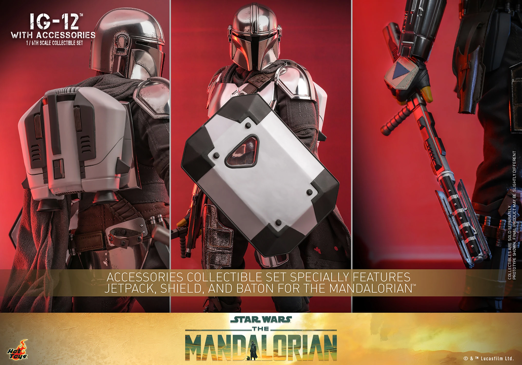
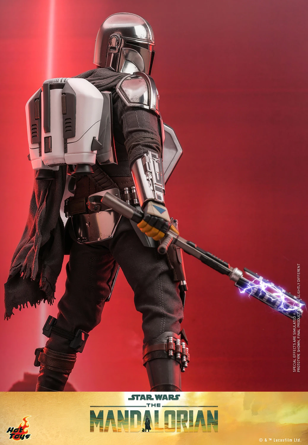
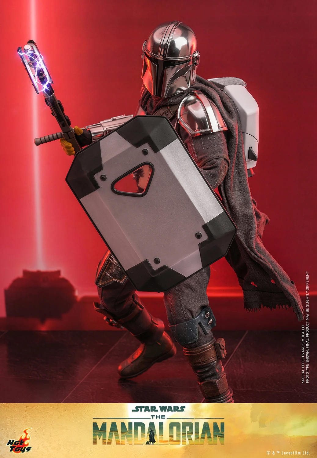
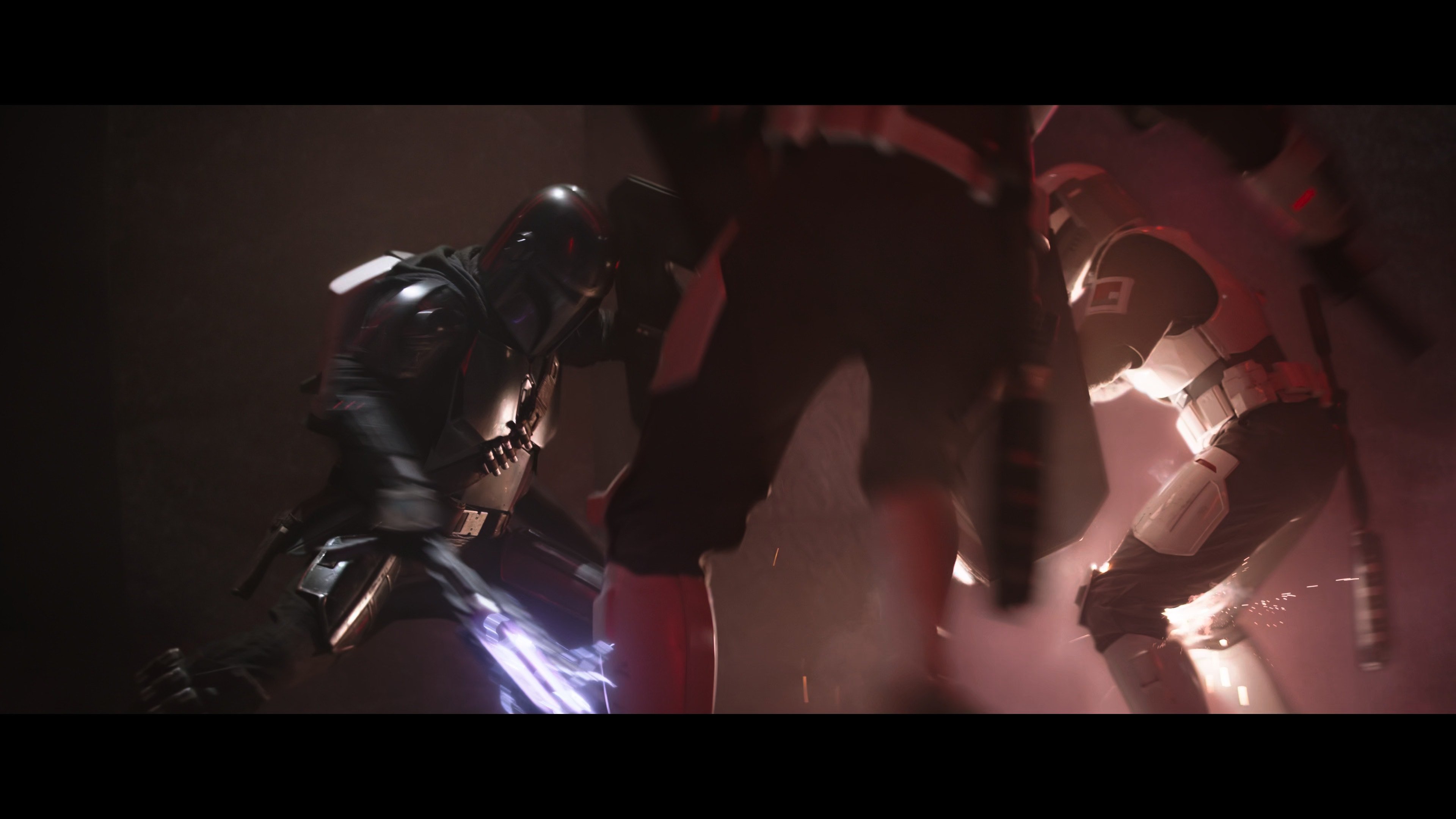
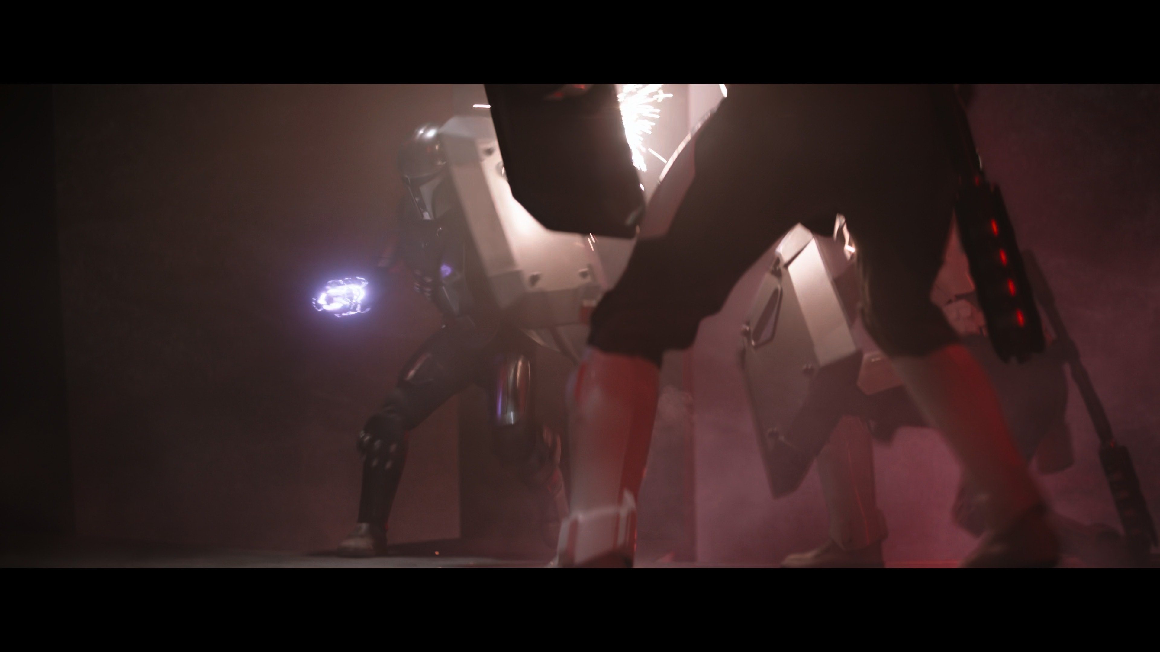
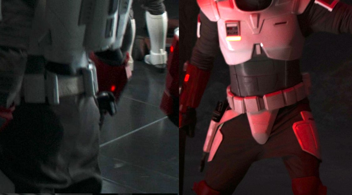
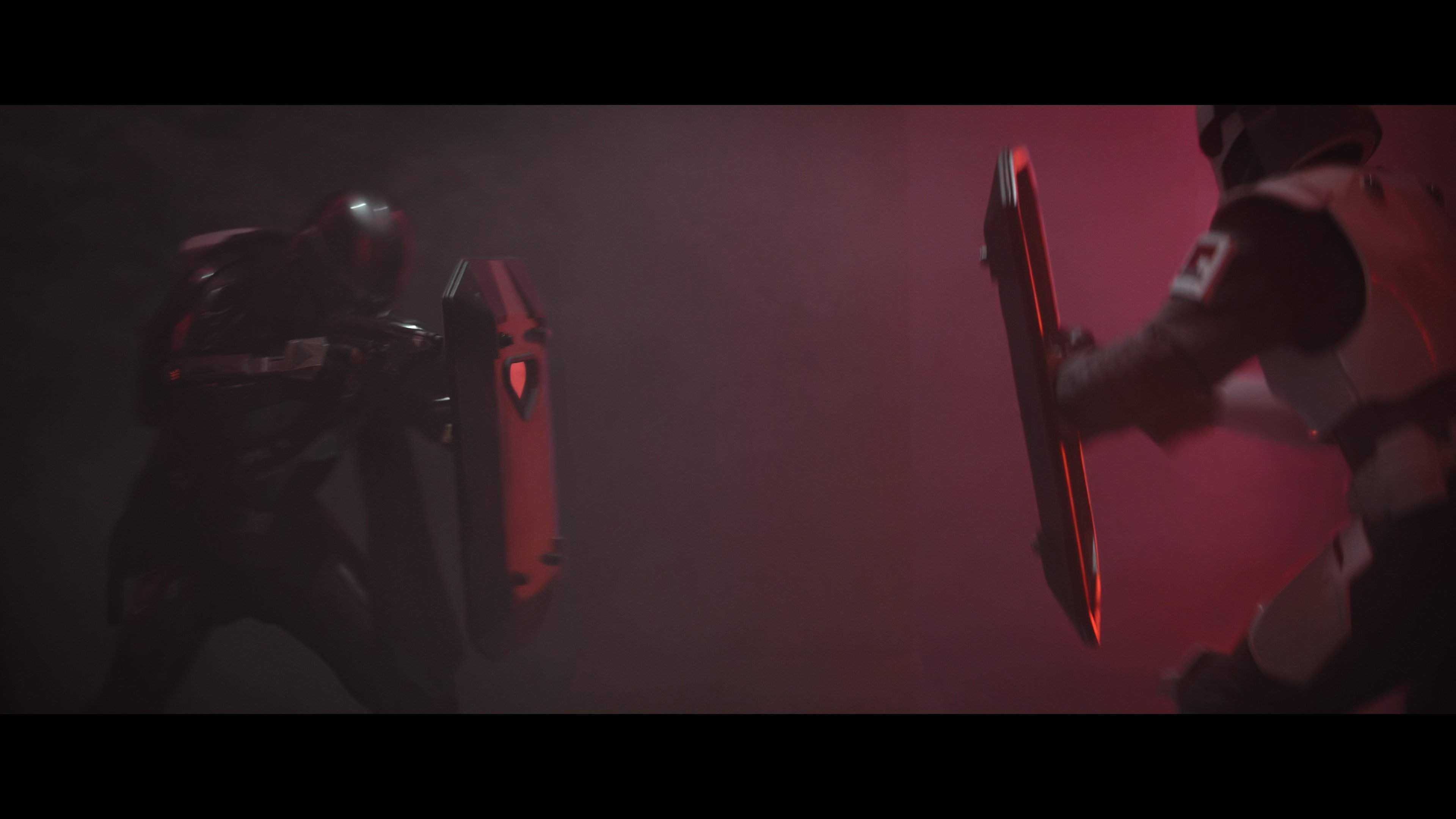
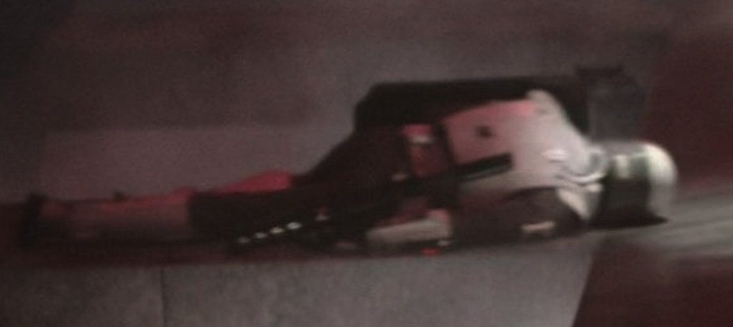
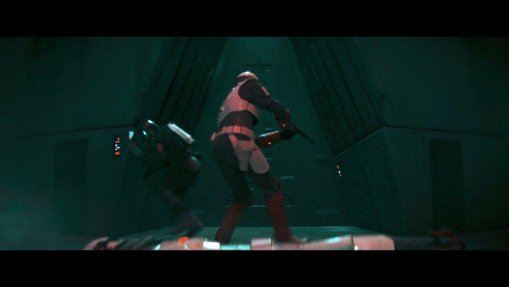
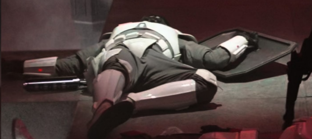
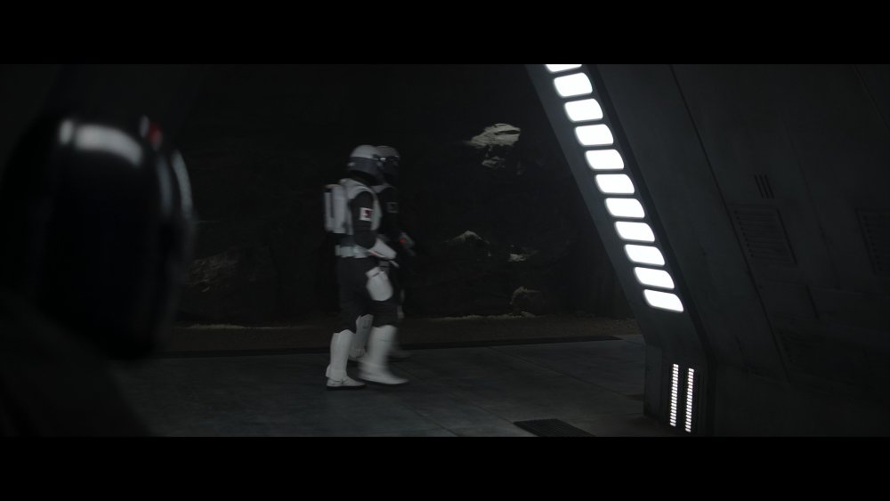
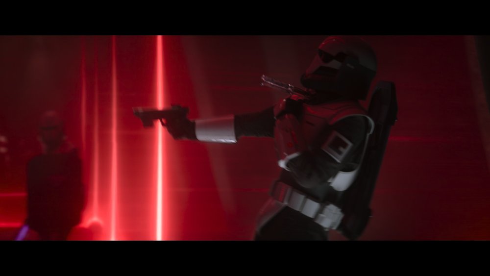
Baton, Shield, Blasters, Jetpack References


 1 point
 -
Hello everyone. I'm finally jumping in after decades of "being too busy". I have my heart set on an RS prop masters kit. Just waiting for their next run. Very much looking forward to getting it and putting it together. I'll be happily spotting until I can troop myself. Thanks for having me.1 point
-
Baton mounted on belt Pistol and thinner holster - red accent troopers Sidearm standard troopers No holster (or reversed image) Rifle Shield Shield mounted on backplate


 1 point
 -
Always best to do any trimming once you are finished and fully kitted up, parts can move once dressed and I've seen some with huge gaps because they trimmed too early. Easier to cut of that to add on1 point
-
I would recommend to wait to the finale test fit to see if there is some issue when walking around.1 point
-
Thank you for pointing me to the legacy stormtrooper threads! I see a lot of useful information. It's a good thing there are numerous similarities between the FEM7 and legacy armor!1 point
-
I love when there’s some Rascally memes from my man Justin! I promise I’ll have one of my own soon. Just gotta sit at my computer and edit a bit. Sent from my iPhone using Tapatalk1 point
-
I only come here to complain about gloves. I don't understand some of you.1 point
-
Small update. Fixed the back cap issue by grinding away the little nubs on the inside of the cap. This allowed the cap to sit at 12:00. The back cap locking lever was repositioned Drilled out the fire selector switch hole for the larger BlastFX switch. Hopefully this will fit in the grip as it is a bit thicker than the Blasterfactory one. Drilled a hole through the scope mount and scope rail in preparation for wire running. Spent lots of time trying to figure out component location and wire routing. Nubs inside the cap were grounded down by about half, allowing the cap to rotate to the new position. I thought of drilling new holes and repositioning the cap locking ring, but the new holes would overlap the existing ones. Old locking tab position vs new one. Hole drille dout and BlastFX fire selector switch in position. This post is taller than the old one, so it may need to be cut down. Also, the lever that attaches to this is 1/2 moon shaped, so I will have to cut this in half vertically as well. Difference in thickness. I haven't tested the grip to insure the new switch will fit... Scope mounting holes before drilling wire access holes. Thankfully the scope is nice soft aluminum. The mount is sheet metal but easily drilled through. Scope wiring will run up through the cope rail mounting hole at the front, along the underside of the rail, and up into the scope. The scope display circuit board in the front brass ring. I will take a hint from the Blast FX FB page about this build and grind out little triangular slots in the brass. This will allow the dirsplay to sit into the brass about 1 mm or so for security. And here is one issue I had with my DLT build. These wire are VERY small and any minor manipulation leads them snapping off from the components ate the solder joint. I had simply positioned everything in the blaster as a test, and as I was manouvering the speaker out noticed a wire had snapped. Just adds to the fun... What I've come up with for the BlastFx component location. I forgot to add the scope and Hengstler counter for the pic, so I just blocked them in. I wanted to keep the magazine with all its guts intact, but I don't think this will be possible. I will place the Main and charging circuit boards in the magazine well, then slip the now empty magazine over top of the two. The laser will be mounted behind / under the bayonet lug. You should see only about 1/2" of wiring from the laser before it disappears through the main body cooling holes. The light strip will be glued along the inside bottom of the main tube. Battery will be attached to the inside top of the tube. It shouldn't be visible as I'll wrap it in black tape and the T-tracks will cover the top and side holes. The little sliding on/off switch will be tucked away in one of the cooling holes on the bottom, or I may move it to the Hengstler counter. Not sure yet. There is a push button mode switch that is used to set preferences, cycle through digital menu's, etc. I'll try and rig this to the existing Hengstler rest button on the counter. The speaker is the main issue. I want to attach is to the back cap so it points forward, but this is not possible. The speaker could JUST fit inside the tube if it wasn't for the little soldering tabs that stick out the side. If I lay the speaker flat and rotate it slightly, it can just fit. I will have to trim back the main cocking spring slightly so it doesn't jam up against the speaker. I may also install a carboard tube (painted black) in the main body so it "warms up" the sound. When you put a speaker in a metal tube it makes it sound very tinny. Stay tuned!1 point
-
Welcome to FISD . You may want to take a look to this section for some reference for your build. https://www.whitearmor.net/forum/forum/151-legacy-stormtrooper-build-threads/1 point
-
Hi Robert, welcome to FISD. We recommend you to read this thread about armor vendors.1 point
-
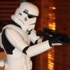
Haha, ok, I swapped out the thumbnail size for the original size images in my post. They're still not great - bad lighting and I was taking them from a distance to reduce perspective lens distortion from my phone camera. But I'll try and get some better quality pics here soon, "for the people"1 point
-
Very cool! I purchased those files during the initial crowdfunding-type offering, but have yet to get into 3D printing. Someday… Sent from my iPhone using Tapatalk1 point
-
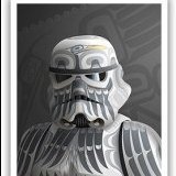
I can add that in no problem. As all things this is only a first draft to make sure it looked different at a glance with the other wiki origin docs I have ready and waiting for photos and language. I'll make the change when I'm back home from a work regional trip on Wednesday. I shall add that to the context section, so it is clear.1 point
-
I believe the description/CRL title should be as above, "Stormtrooper, Tales From the Galaxy's Edge: Last Call - First Order Lt. Gauge" or similar, since the character appears in the specific "Last Call" game expansion only, and is a named First Order Officer. Or I guess however you're doing Captain Cardinal or Commander Pyre, so it's consistent... I don't believe there is enough substantive difference from the TFA First Order Stormtrooper to warrant a regular stormtrooper from the game in general. I like the description though, and am glad to see it in motion, thank you!1 point
-
It looks beautiful, but the people demand bigger/better quality pics!1 point
-
I was able to finish the rest of the preliminary cutting of the excess material today (at least what I am able to cut prior to measuring). Here are some photos showing the arm and shoulder pieces prior to cutting, after cutting, and the whole set after preliminary cutting! Now it seems I am in a holding pattern until my friend can help with the measuring and fitting. Perhaps I should spend this time to plan the strapping. Hmm....1 point
-
Thank you! I'm trying to be super diligent and careful as I progress! I want to make sure I do things right.1 point
-
Thank you, I may very well do that. I'm still in the middle of my move but intend to start spotting ASAP. I figure that's a good way to meet folks and maybe learn along the way.1 point
-
I'm still undecided on a full build vs commissioning and then just tweaking to make sure it fits perfectly. I'm not in a rush either way.1 point
-
Vry nice indeed1 point
-
Finally got my prints back from Corellia Creations and they look amazing! The brow came back a bit warped, but once it's affixed to the rest of the helmet you'll never know. But I'm going to experiment with some rubber trim first and decide which looks best as I get into it. The alignment keys worked fantastic and it virtually holds itself together. I did use some tape between parts so I could handle it (except for the brow trim, that's held on with fun-tak). I temporarily attached some test pieces I had made previously, but I intend to reprint them. Here's some preliminary shots of the raw print.1 point
-
These two photos show my progress so far. The first photo serves as the "before" image, with the pieces having been laid out just after coming out of the shipping box. The second photo shows the work I have done so far. This work encompasses cutting much of the excess material off the areas of the pieces that will not butt against or overlap other pieces. I am leaving just a little bit of the excess material on with the expectation that this final bit of excess will be removed when I sand the edges with the sanding bits of my Dremel and a sanding block. The excess material in places that may butt up or overlap will remain until I have the opportunity to measure and then fit the pieces, which needs to wait until my friend is available to help me (I imagine this will be way too aggravating if I do this part myself). Anyway, here are the two photos:1 point
-
Quick update after some minor blaster surgery. I mostly reassembled the E-11 so I could get a better understanding of where I can place the electronics. The muzzle cap had a large groove cut into it with a hacksaw and various Dremel bits to allow the installation of the muzzle flash device. I won't be using the kit barrel as it is really not needed. it can't be seen and leaves less room for electronics in the forward tube. I'm trying to place all the electronics in the main tube so I can keep the guts of the magazine in place I removed the installed fire selector switch in preparation for the BlastFX one. I found that the cocking action is very stiff and "grindy". You can actually feel and see little slivers of aluminum powder and shavings every time you weenie the action. This could be worked out over time, but I've never seen anyone cocking the action on an E-11 in the movies, so I don't need it here! Blaster is mostly reassembled. You can see that the selector switch is removed. I'll have to drill out the hole slightly to accept the post from the BlastFx version. I may also have to cut the post down slightly so the selector lever sits flush with the left side of grip body. And yes, I was listening the Gordon Lightfoot while grinding away. Something soothing about The Wreck of The Edmund Fitzgerald as you grind away at metal... I discovered a small issue with the end cap that I hadn't noticed before. The main tube has a grooved locking ring attached with 3 screws (visible in image) to the rear of the tube. This allows the end cap to lock into place. You basically line up little tabs on the inside of the cap with the grooves, push in slightly against the main spring, and turn clockwise. Once locked into place my end cap sits clockwise slightly, with the top being aligned at roughly 12:30 instead of 12:00. Locking ring on the Blasterfactory website. How my end cap sits vs how it should attach: On the real Sterlings there is a locking device (tab?) on the bottom just forward of the end cap. It has a spring and pivots when pressed which disengages a little tab that allows you to remove the end cap. Blasterfactory has included this little locking device with a spring, which is nice, but it is mounted about 1/4" forward of where it should be. It is also slightly off the bottom centerline of the main tube. Locking tab too far forward. The backend should overlap the end cap. There is a little stub on the inside of the locking tab that should sit in the small groove in the end cap. In the right image you can see the centerline of main tube in blue. My cap is locked in position with the center in green, and the black locking tab is off center in red. These "should" be easy fixes. Both the end cap locking ring and the black locking tab are held on with screws. I just have to re index everything and drill new holes. The muzzle cap surgery took a couple hours of cutting, grinding and filing down. I started with a couple simple hacksaw cuts with the muzzle held in a vice. I then used various Dremel bits to hack and grind away at the material. Thankfully this is aluminum and not steel! Unfortunately, the Dremel skipped a couple times and put some minor dings into the nice smooth paint job. These will be easy to sand out, but will necessitate a new paint job. Here it is basically done. I had to grind a small rounded bit out of the forward end of the slot to accommodate the led bulb of the flash unit. It's hard to capture in a picture, but I also had to grind a rounded groove at the bottom of the channel to accept the round circuit board of the flash unit. If I attempted to have the entire groove the depth needed for the flash unit, I may remove too much material and get close to the front sight cutout. Flash unit in the groove. The flash unit circuit board is a rounded "star" or "flower" shape, and one of the points / petals sits in the additional round groove at the bottom of the channel. In this pic, the muzzle piece is held upside down. So the muzzle sits just at the bottom (top in this pic) of the big hole. If I tried to center it I may remove too much material and get too close to the front sight groove. By me carrying out the surgery the muzzle flash board sits about 1/2 to 3/4" more forward. so it will be seen better. Back to the workbench!1 point
-
Wiki Doc back end is constructed, haven't fleshed it out as yet but intro title is complete
 1 point
 -
This thread right now1 point
-
A quick general overview of what I will be dealing with. I've also updated the links in first post with my DLT build so you can see functions of the BlastFX system. I received the blaster fully assembled, which may have looked interesting going through customs. I disassembled everything last year in preparation for this build. Here are all of the parts, with the BlastFX system at bottom right. Some components, like the folding stock, grip assembly, etc, will be broken down further for ease of painting and wiring installation. I'm still deciding where all the wiring will go. There is only so much length of wire, so I have to be careful about where I put everything. I can use wire extensions like I did on my DLT build, but this adds unnecessary bulkiness to some wires which could hinder the build further. I've seen a couple builds where much of the electronic circuit boards were in the mag and mag well. This allowed the rear main tube body to remain relatively empty. You could then pull back the cocking handle and bolt as I guess something to do...? As I can't see this having a purpose in the "real world" of Star Wars, I may transfer some electronics to the main tube. As long as they remain hidden when viewed through the large cocking handle groove I'd be okay with that. I'll have detailed pics and diagrams later, but here are the blast FX components and possible installed locations (clockwise from bottom of wire harness): Main control circuit board. It's hard to see, but there are two little R/B wire coming out of the unit to the left. These may have been from the vibration unit I had to steal from this kit for my DLT. Can't remember now.... In mag well or main tube below SMG bolt. Speaker main tube at back Barrel lighting strip attached to inside bottom of main body tube so it reflects upward Muzzle Flash Device Black muzzle cap Laser Possibly shining out of a small hole drilled in front of magwell Mode selector button Attached inside the Hengstler counter and activated by the original counter "reset" button Trigger switch Inside grip behind trigger. Blaster Factory includes one and this is a match, but it is already wired into the BlastFX system Rotary fire selector (single shot, auto and stun) BlasterFactory includes a rotary selectro, but from my sources it is finicky and hard to wire correctly with the BlastFX system. I'll probably just remove it. Scope display (little black square that needs to be soldered to wires) Blast FX left this disconnected for easier routing of wires into the scope. VERY smart and thankyou! Back of scope Main display (little black rectangle). Same wiring considerations as the scope Inside Hengstler counter display area Grip vibration unit (little black circle). My DLT hand one and I remember the thin wires broke at the unit. I think I had to steal the one from this kit to service the DLT. I then ordered a few more on Amazon. I'll have to attach this vibration unit to the wires to see if that is what they are for...Somehwere in grip Main battery: 3.7V 2000mAH 7.4Wh I may have an issue with this rectangular battery. It doesn't fit the mag well in a nice way, and may not leave room around it for the other pieces. Magwell or main body. TBD Charging circuit board for battery. This is an after market piece I bought online: Powerboost1000 Charger. It includes a USB charging port which I will have to incorporate into the blaster somewhere. I'm using this so I don't always have to remove the battery for charging. I'm not sure if I want to cut a USB size hole into the body of the blaster, and I don't want to disassemble the blaster to get at this USB port, so I may put the circuit board somewhere easily accessible like behind the main tube rear cap, or in the mag well behind the magazine. Magwell or main body On / Off sliding switch for power source. Small black thingy to left of the charging circuit board. This has to be somewhere easily accesable. Possibly hidden at back of magwell, or in Hengstler counter Detailed pic of the displays, included scope display magnifier and red filter, as well as a vibration unit. Battery, charging circuit board and sliding on/off switch: I actually felt real bad about taking apart a real Hengstler counter to add electronics. I debated purchasing another blaster, keeping the counter intact to replicate a screen used one, then having another with electronics for trooping. Unfortunately I can't justify that cost. The little baggie on the left is all the tiny counter parts I won't be using. There's a surprising amount of tiny springs, gears, pins and bushing in this little device. There will be more detailed shots of this and other pieces as the build continues. The magazine. I paid extra to receive a real sterling magazine that was cut down just like the movie used ones. I forgot to include the magazine "roller follower" in this shot, and there are some screws and springs missing from this shot. You'll see them later. I probably can't use any of the internal mag bits because a few of the electronics will sit in the mag and mag well because of lack of internal space in the blaster. Main body, t-tracks, muzzle cap, fake barrel and front sight. The way that Blasterfactory designed this all to go together, while retaining the external features of the Sterling perfectly, is quite ingenious. You won't be able to see the barrel as the T-tracks block most of the holes. And now the first build issue.... This is the muzzle cap that screws into the front of the barrel unit, and pictured is the muzzle flash device. Technically, the flash device will have to fit somewhere inside the muzzle cap shining out the front, but there is no way to do this right now. I was thinking I cold lose the barrel, but it is used to attach the front sight, as well as the back of barrel might be used to stop the bolt from sliding forward or rattling around. I could cut a groove into the bottom of the muzzle device to allow the muzzle flash unit to slip into, but there is an issue with this (next pic) This is the backside of the muzzle device after it is detached from the barrel. You can just see that the muzzle flash device circuit board partially covers both screws holes. This prevents the screws from passing through and screwing into the barrel unit. I can't trim the circuit board down sufficiently What I could do, and would require the same surgery is: Cut a suitable groove / slot to slip the muzzle flash unit upwards into the muzzle device. Cut the screws down by about 1/2" When it come time for assembly, I just glue (E6000) and clamp the barrel to the back of the muzzle device Glue the remaining heads of both screws into their holes. This will allow the appearance that they are gripping into the barrel. The included round rotary and trigger switches. They will be replaced by the BlastFX versions. You can juts make out a hole above the black trigger switch that will allow wires to pass through. I'll have to makes sure that the BlastFX rotary switch functions line up with the Fire /Auto / Safe marks that are on the other side of the grip. That's it for now.1 point