Thrawn's guard Posted October 1, 2015 Author Report Posted October 1, 2015 (edited) Most of my parts have now arrived so I hope to start building the power cylinders next week. In the meantime however I have been playing around with building a prototype using a mixture of parts that I have 3D printed and also some parts that I will probably use for the final build (fuses). For the final version I envisage using the following: - 1) Metal tubes to for the cylinders. 2) Metal caps to form the ends of the cylinders. 3) Metal base plate. 4) Metal ‘shaped’ back plate. 5) Metal fuses, (From Tino’s completion kit), with green stuff to for the ends. 6) Thin metal wire to connect from the fuses (From Tino’s completion kit). 7) Textile covered wire (From Tino’s completion kit). 8) Power cylinder support plates as shown in my post above either 3D printed or formed from 1mm thick abs sheet. 9) Small wing plates fixed to the cylinder either 3D printed or formed from 1mm thick abs sheet. 10) Nuts and bolts (From Tino’s completion kit). 11) Red plastic pieces which can been seen in the vent slots in the cylinders. I will probably use some form of insulating plastic as suggested in Tino’s cylinder tutorial. As noted above this is very much a prototype at this stage however as always please feel free to make any comments you wish. Edited October 1, 2015 by Thrawn's guard Quote
Thrawn's guard Posted October 3, 2015 Author Report Posted October 3, 2015 (edited) Well I now have the majority of the parts that I need to make my power cylinders (I will find something suitable for the resistors soon). Firstly I decided to make the base plate using some 0.9mm thick steel plate. I used the 3D printed base to mark out the profile of the base plate and hole location on the steel plate and then used a rotary drill to shape the plate and drill the hole. In hindsight it would have been better to use a softer metal which would be easier to cut and drill. My next task will be to cut and and shape the end plate. Edited October 3, 2015 by Thrawn's guard 1 Quote
Novak Dimon[TK] Posted October 4, 2015 Report Posted October 4, 2015 Nice work Chris!<br> Do you have proper tools for bending the steel plate? Perhaps you can make the base plate of one piece. Quote
Thrawn's guard Posted October 4, 2015 Author Report Posted October 4, 2015 (edited) Thanks Jever. Unfortunately I don't currently have the tools to bend the metal plates so am looking at joining two plates together. I may however build a workbench and fit a vice to help with this if I build any more in the future. Edited October 4, 2015 by Thrawn's guard Quote
Thrawn's guard Posted October 6, 2015 Author Report Posted October 6, 2015 My power cylinder build has been going a little slow as I have had family staying however the good news is that I should now have more time to work on them and get them finished. I do have one quick question if anyone knows the answer. With regard to the small resistors which are located next to the textile insulated wire does anyone know the exact length and diameter ? As far as I can see we only have reference pictures, which I can use to get something about the correct size, but thought it worthwhile checking just in case I have missed it somewhere. Quote
Thrawn's guard Posted October 7, 2015 Author Report Posted October 7, 2015 The next step was to look at making the back plate. For this I am looking at using some thin aluminium strip (previously an aluminium ruler). I used a rough 3D printed version as a template to mark out the profile and holes using a mechanical pencil and will look to start shaping and drilling hopefully tonight. Quote
usaeatt2 Posted October 7, 2015 Report Posted October 7, 2015 With regard to the small resistors which are located next to the textile insulated wire does anyone know the exact length and diameter ? Hey Chris, here's a picture of the resistors Andy identified in his research PDF as screen used. The body is 23mm long, with 1mm "caps" at each end for a total length of 25mm. Width is 5mm. Apparently, these were being given away (free!) at one point, but most supplies have been exhausted now. I have 6 loose originals that will forever remain untouched...I would never be able to paint such a rare item flat black!!! But they are perfect for display or measurement!!! Quote
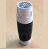
Thrawn's guard Posted October 7, 2015 Author Report Posted October 7, 2015 Thanks Aaron though I may however have misidentified the parts I was querying (Though the picture provided above is also of great help). I was referring to the small cylindrical items Tino makes from grey plastic offcuts from a model kit as shown in the top right picture borrowed from his power cylinder modification tutorial shown below. Quote
usaeatt2 Posted October 8, 2015 Report Posted October 8, 2015 Sorry Chris...I was on my way to bed when I responded. I posted capacitors, NOT resistors. Tino's images straightened me out...THANKS! The RESISTORS measure 9 to 9.5mm long and 3 to 3.5mm wide. There's a tiny bit of variance. You can probably find these anywhere for cheap, but if not, PM me and I'll mail them to you. These were extras from a job I was doing at work... Aaron 2 Quote
Thrawn's guard Posted October 8, 2015 Author Report Posted October 8, 2015 (edited) Thanks very much for posting these images Aaron and for the offer to send some resistors. I'm pretty sure that I should be able to get some but I very much appreciate the offer. Edited October 9, 2015 by Thrawn's guard Quote
Onlyalad19 Posted October 8, 2015 Report Posted October 8, 2015 You're off to a great start on your scratch built power cylinders Chris. I can't wait to see the final product! 1 Quote
Thrawn's guard Posted October 9, 2015 Author Report Posted October 9, 2015 In order to drill out the holes in the backing plate I will need to use my drill in the garage but need the daylight as I don’t yet have any lighting in there so this task will have to wait until the weekend. As a result I thought that I’d do a little work or the power cylinders themselves namely forming the end caps. I took one of the large fuses and carefully marked out a 4.3mm wide section to the end of the metal caps. A rotary drill was then used with a cutting disc to carefully cut through the metal and glass below. After I had cut the first three I realised that the easiest way to mark out the end cap and ensure that you marking could be easily seen was to wrap a small amount of masking tape around the end of the fuse, set a pair of callipers to 4.3mm and use the ‘teeth’ to gently mark out on the masking tape. The most difficult part of the task however was to remove the small section of cylindrical glass left in the end of the cap without causing any damage. Finally I test fitted the end cap of the brass tube. 1 Quote
usaeatt2 Posted October 9, 2015 Report Posted October 9, 2015 NICE. I like how you cut the caps. Different than what I did, but more effective I think. They sure look nice and shiny! I removed the caps using a torch first, then cut them to the correct size. If you heat the caps, the solder melts and the cap just falls off. The heat discolors the cap a little, but it's not a big deal since they'll ultimately be painted. It's always good to learn a new trick! Thanks! Quote
Thrawn's guard Posted October 9, 2015 Author Report Posted October 9, 2015 Great tip about heating the end caps to get them off the glass tube Aaron. If I make some more at some stage I'll give that a go. We all share and learn from each other which is what is so great about the FISD. Quote
Thrawn's guard Posted October 9, 2015 Author Report Posted October 9, 2015 Just a short update this time to show what I have been able to do after getting home from work. I have cut the brass tube to length, (46mm), with a cutting disc on a rotary drill before test fitting the end caps. Next I needed to form the slots at the rear end of the cylinders (7.3mm long and 3.5mm wide). Firstly I marked a line around the brass cylinder 7.3mm from the end using digital callipers. Then taking a circular cutting disk I carefully cut a thin slot out in both walls of the rod to the full length (7.3mm),. The same cutting disk was then used to gradually widen the slots until they were 3.5mm wide (This distance was checked regularly with the callipers). The photograph below shows the cylinders with the notches cut at one end and the end caps loosely placed I to position. I also show below the distance from the end of the cap to the end of the slot (The caps extend the length of the brass rod by 0.5mm at each end). 1 Quote
Thrawn's guard Posted October 10, 2015 Author Report Posted October 10, 2015 Today I had a go at making my backing plate from a strip of aluminium. Taking the aluminium strip that I marked out in my earlier post I carefully marked out the centre of each of the 10mm diameter holes for the power cylinders to fit through and also the three 5mm diameter holes for the fuses to fit through. Once that I was happy I had marked them out correctly I used a sharp point to mark out a small starter hole (which will help keep the drill bit located correctly). I then slowly drilled out a 2.5mm diameter hole at each of these locations. The holes were then drilled out fully using the correct drill bits. The outer shape of the backing plate was then cut out using a cutting disk on a rotary drill. Finally a combination of a sanding tool and a circular hand file were used to form the circular recess in the top of the back plate. The edges were then cleaned up using sandpaper, 1 Quote
Thrawn's guard Posted October 10, 2015 Author Report Posted October 10, 2015 I couldn't resist having a quick tried fit to see how things are coming together. It seems to be working out OK so far but I still have a bit of work to do before I have them complete. Here are a couple of quick pictures to show you what I have so far. 1 Quote
Twnbrother Posted October 11, 2015 Report Posted October 11, 2015 Impressive. Most impressive. You are making me want to rework mine. Great work 1 Quote
Thrawn's guard Posted October 11, 2015 Author Report Posted October 11, 2015 I'm glad that you like them Mike. I did try to see if I could get a set of Andy's resin power cylinders but wasn't successful so thought that I'd give them a go myself. To be honest I am glad that I did as I am enjoying the process. If nothing else it is also prolonging my build and I'm not sure what i will do with my time once it is complete......perhaps build a biker scout pistol, light-sabre hilt or perhaps maybe even some armour. 1 Quote
Thrawn's guard Posted October 11, 2015 Author Report Posted October 11, 2015 Credit where credit is due Tino has done a great job making the 3 capacitors in his “How to make your Power Cylinders more accurate” thread so rather than try to reinvent the wheel I am going to use this as the basis for my build. The first job is to take the 5mm diameter aluminium rods provided in Tinos completion set and make the curved profile to the ends. In order to do this I clamped my hand drill to my workbench so that I could operate the trigger with my left hand. The aluminium cylinders were then placed in the drill chuck and a small hand file used to shape the ends of the cylinders whilst the drill is operating. Once that I was happy with the profile on each end of the cylinders I mixed a small amount of green stuff to form in to the ‘caps’. This was achieved by rolling a small amount of green stuff, approximately a 2mm diameter sphere, placing it centrally on the end of each cylinder and then genially pushing it so that the overall thickness of the ’caps’ are about 1mm. Wetting your fingers before pushing the spheres in to shape will stop the green stuff sticking to your finger rather than the end of the cylinder. When I was happy with the shape of the caps I cut six 25mm lengths of 0.45mm diameter wire, (fuse wire could be used for this purpose), and pushed one piece centrally in to each of the caps. I can cut this wire to length later but thought it better to have more than is needed rather then less. This is what I ended up with. 1 Quote
usaeatt2 Posted October 11, 2015 Report Posted October 11, 2015 So cool... You're bringing back lots of memories! Man, I LOVE this stuff! 2 Quote
Thrawn's guard Posted October 17, 2015 Author Report Posted October 17, 2015 Thanks Aaron it is good fun and even better when you have something at the end that you are happy with. Quote
Thrawn's guard Posted October 17, 2015 Author Report Posted October 17, 2015 (edited) I measured the outside diameter of the end caps,(10.2mm), and then set some digital callipers to half this distance, (5.1mm), in order to be able to find the centre point of the end cap. Using the metal ‘prongs’ on the callipers I gently marked a line on the end of the end cap, rotated it approximately 90 degrees and then repeated the process. This gave me a cross mark as can be seen on the photograph below which accurately indicates the centre point. Once I had the centre located I carefully drilled a small pilot hole in the end caps. I then opened up this pilot hole to a diameter just slightly larger than then diameter of the bolt thread (The diameter of the bolt thread used was 1.6mm). Aaron (usaeatt2), previously advised me that if I was to heat up the end caps the solder melts and the cap just falls off the remainder of the metal fuse element. I don’t have a blow touch however I do have a soldering iron so decided to have a go removing the elements using this. All I did here was hold the end of the fuse element with a plumbers spanned whilst I heated up the solder and as Aaron suggested once they were hot enough they simply fell off. Thanks for the tip Aaron it proved both easy and prevented me from possibly damaging the end caps trying to remove the elements. Finally I trial fitted the nuts and bolts to one end of the power cylinders (Nothing is glued together at this stage). If anyone has any tips or suggestions at this point it would be much appreciated before I start gluing things together. Edited October 17, 2015 by Thrawn's guard 1 Quote
Twnbrother Posted October 17, 2015 Report Posted October 17, 2015 I am continually impressed by your work. Great job 1 Quote
Twnbrother Posted October 17, 2015 Report Posted October 17, 2015 After seeing this power cylinder build I have to redo mine. What size fuse did you use for the caps? Is the cylinders 10mm? Quote

Recommended Posts
Join the conversation
You can post now and register later. If you have an account, sign in now to post with your account.