

11b30b4
-
Posts
390 -
Joined
-
Last visited
-
Days Won
6
Content Type
Profiles
Forums
Gallery
Articles
Everything posted by 11b30b4
-
Parquette, I agree and have made plans to get some of the Vac Formed ROTK stuff that NaturalBorn and Head Shot Props are working on. BTW, I just got a black Series helmet so is there any change you can fix the pictures on your how to modify thread? Most of the pictures of what you have done to modify the helmet are not showing up. Update, Ok, the repair has commenced. First, I found some white craft foam that is slightly wider than the inside of the drop boxes. I am confident that the drop boxes are causing all the damage to the top of the thighs. I cut and glued some of this foam inside the drop boxes and this should fix this. I will add the Velcro straps soon. Next, I glued a piece of HIPS to the inside of the back plate to fix a crack. I still need to sand this and add more Velcro to this part. With the cracking of the shoulder strap, I have decided to attempt to make some rubber or foam shoulder straps. First, I needed to make a flat version of the shoulder strap. I used some ¼” plywood and I cut a lot of these ½ rounds then glued them in place on the plywood. I framed out a box and glued the shoulder strap inside. Then I filled it with Smooth-on Rebound 25. I would have used OOMOO 30 but the OOMOO I had, went bad and solidified. So Rebound -25 is a bit thicker but its still silicone. Once the mold cured, I pulled it out of the frame and removed the shoulder strap. So far it looks good. Well that’s it for the update so far. Thanks for the interest.
-
11B30B4's RO T-21 Build (MkI -MkIII)
11b30b4 replied to 11b30b4's topic in MiniMag PTL Missile Launcher, T-21, RT-97C (MG-15)
“Time to wire that bad boy up with some electronics lol”… Ukswrath, there may be a time for that in the future but that time is not now. I made the trigger functional in case I decided to do just that in the future. Since most of the parts were glued in place with E-6000, deconstruction to add electronics will be somewhat difficult. DEVOLVER, thank you for the compliment. Update, Well, like I said previously, I did not like who the “D” seal looked so I found a better option. I purchased about 25’ of 7/64” Windshield washer vac tube. This hose is a stiffer and thicker walled rubber tube. So I removed the “D” seal. Next I drilled a small hole for the washer tube to be inserted into the barrel shroud on the bottom near the collar closest to the feed tray. I spread some E-6000 all over the barrel shroud where the washer tube will be wrapped. I locked the starting end of the washer tube in the hole and started wrapping the tube. Keeping constant tension on the washer tube as I wrapped it around the barrel shroud till I hit the end point. I drilled another hole and locked the end of the tube inside the hole. Presto, a better looking T-21. Well that finishes the Rogue One T-21. Thanks for the interest. -
"Be great if they could get on the forums and post photos of their progress" gmrhodes13, one of them has done just that. Daetrin, I completely support changes to the CRLs if they are based on "legitimate and Provable" needed changes that bring the requirements in line with "actual cannon" armor. What I do not agree with is the "hay, it looks like this is whatever, so we should change the CRLs to reflect that...". It may look like whatever, but if you can not prove it is whatever, then do not make the changes. A perfect example of this is the ASP baton holster we talked about some time ago. We should not include something in the CRL's unless we can prove it. Just my perspective on the CRLs and how they are developed. Overall, I am very pleased with the CRLs have been developed. I like that we have all had the opportunity to impact the CRLs and the staff here on FISD are very open and welcoming to changing and correcting the CRLs.
-
I would also like to mention (in case someone does not know) there are two groups/ companies working vacuum formed Rogue One TK kits. The first is NaturalBornDT and his group The DarkSide Closet and 850 Armor works. The other company is Head Shot Props (HSP). both of these kits look promising and I will be getting one or both kits. These kits should not have some of the issues noted with the fibergalss kit but they may have other issues. I will not know until I get my hands on them. So for people to be able to produce kits for us, there needs to be a standard that does not go through frequent revisions. If we make too many changes, these kits will never get made and we will be as limited as we currently are. Now that Solo has come and gone, perhaps someone will get their hands on one of the Solo TKs and we can learn a lot from it (fingers crossed). While we are talking about other kits, I contacted HSP and asked about rubber shoulder straps like the clone armor guys have as well as Rogue One versions of rubber handguards. They are looking into making these for the Rogue One TK kits and as an add on for other ROTK kits like Jim's kit. As far as CRLs are concerned, if these rubber options look the same as the existing stuff, I see no reason they would not be approved by 501st/ FISD. As long as we do not restrict them in the CRLs they should be allowed.
-
Hey guys, let me pop in with my thoughts on this stuff. I think we have sufficiently proven that the all limb joints are overlap and not butt joint. As to which side is overlapped, it seems like common sense the at all joints should look closed from the outside like the biceps pic posted above. I do not think that it needs to be spelled out in the CRLs except to say that all joints should be overlap and can have a butt joint appearance. Regardless, the cover strip or "simulated" cover strip cover the entire joint so it would never bee seen anyway. As for the hole on the back plate. I moved mine and re-drilled it but I then add a backing piece of polystyrene that was painted black. again, I do not see a need to specify that it is a hole or a depression, as long as it has the desired look. I understand many of us feel the need to be as accurate as possible but until someone can put their hands on an actual screen used set of armor, we are stuck with pictures and there is just too many issues with looking at pictures and gleaning anything further than what has already been discussed here. For example, are the inside of the HOVI mics black or white? I have looked at a ton of images since this question was first posed and honestly, I have found images that support both but none can confirm that its not a trick of lighting. I honestly feel that unless its something obvious and/ or integral to the armor design (ex. cut out vents that are backed with a blue material on the helmet) we should leave well enough alone. Just my 2 cents.
-
11B30B4's RO T-21 Build (MkI -MkIII)
11b30b4 replied to 11b30b4's topic in MiniMag PTL Missile Launcher, T-21, RT-97C (MG-15)
Update, I applied the clear coat and hung the rifle to dry. Next, I wrapped the “D” gasket and put the sling and tac light back on. I do not like how the “D” gasket looks so I will be looking for a different solution. But my Rogue One T-21 is done for now. If I change out the “D” gasket, I will post an update; otherwise, the gun is done. Thanks for the interest. -
11B30B4's RO T-21 Build (MkI -MkIII)
11b30b4 replied to 11b30b4's topic in MiniMag PTL Missile Launcher, T-21, RT-97C (MG-15)
Update, So I did the black wash last night. Here is a picture of the wash still wet. Once the wash was dry, I took these pictures. Notice how the wash has toned down the silver. I will wait for 24- 48 hours then clear coat everything. After the clear is dry, I will wrap the “D” gasket and that will complete the project. Thanks for the interest. -
11B30B4's RO T-21 Build (MkI -MkIII)
11b30b4 replied to 11b30b4's topic in MiniMag PTL Missile Launcher, T-21, RT-97C (MG-15)
Update, Well I did some dry brush rust on the barrel shroud, collars and front sight. Next I installed the barrel cooling fins and spacer. Next I installed the stock and made the sling. I did some dry brush and wash painting with silver on all the receiver and feed tray parts. The roll marks are visible but they are not as prominent as I would have liked. I glued on the grip scales with E-6000 and they are still curing when I took these pics. If anyone else is looking to do the mask and sand blast method, you may want to paint the feed tray and rear sight first then sand blast and then touch up the paint and they should stand out more. Anyway here are some pictures of how she looks so far. So I will do a black wash tonight and then let it sit for a few days then apply the clear coat everything. After the clear has cured, I will add the “D” gasket and she will be done. One thing I did notice was that the cocking lever in Spool86’s kit is on the right side of the receiver and I have seen several videos of it on the left side. Either it is ambidextrous and can be switched or some models of the Lewis have it on both sides. I am not sure which it is, but it is just a small detail that I am not too worried about. Additionally, in all the pictures of the Lewis I have seen, there are no visible grip screws that hold the scales on the receiver; however, in the two videos I have seen of CGI Lewis guns disassembly, they show screws for the scales? I just glued mine on but it got me thinking, how are the actual grip scales attached? Anyway, just another detail that is not a big deal. So that is the update, thanks for the interest. -
11B30B4's RO T-21 Build (MkI -MkIII)
11b30b4 replied to 11b30b4's topic in MiniMag PTL Missile Launcher, T-21, RT-97C (MG-15)
DEVOLVER, thank you. Update, I sanded and somewhat shaped the PC-7 then sprayed everything with a primer. I made a butt plate from a discarded black plastic bucket. Next I airbrushed the whole thing black. I drilled the mounting holes for the oil tube. Then I sanded, primed and painted the oil tube parts from Spool86’s kit. I decided to mount the stock sling mount on the side of the stock since it looks like that is where it is mounted in the screen captures I posted previously. This is also where is was mounted on some later models of the Lewis. It makes more sense for it to be here and not on the bottom of the stock. This is the barrel cooling fin insert that will go inside the barrel shroud eventually. So I still need to weather the whole thing then let it set for a few days then clear coat it. After that, I will wrap the “D” shaped seal around the barrel shroud, attach the tactical light and stock and make the sling. I am hoping to be finished by this weekend. Hopefully, the weathering will bring out the roll marks. That is it for the update, thanks for the interest. -
11B30B4's RO T-21 Build (MkI -MkIII)
11b30b4 replied to 11b30b4's topic in MiniMag PTL Missile Launcher, T-21, RT-97C (MG-15)
Update, I notched the stock mount plate to allow for the 4 mounting brackets. Next I drilled the screw holes and mounted the brackets. Next, I mixed up some PC-7 and filled in the gap between the chamber and the bottom of the feed tray, the gap between the stock mount and added side detail parts, and the area under the cooling fins and forward of the side detail parts. Once the PC-7 is cured, I will sand and shape before painting. Well that’s it for the update, thanks for the interest. -
11B30B4's RO T-21 Build (MkI -MkIII)
11b30b4 replied to 11b30b4's topic in MiniMag PTL Missile Launcher, T-21, RT-97C (MG-15)
Update, Ok, I attached the barrel shroud with 3 screws that sit under the collar. This picture if the bottom of the barrel shroud. Prior to attaching the barrel shroud, I had notched the top plywood support to that the bolt that would hole the aerial sight in place would be accessible. Once the collar was in place, I drilled the hole and mounted the aerial sight on the top of the barrel shroud. Here you can see the gap under the aerial sight. Next, I cleaned up the front sight. Since I cut off the sight post to drill out a mounting hole, I 3D printed a replacement. Next, I masked off the feed tray and rear sight in preparation for sandblasting. After the sandblasting you can see the roll marks. I do not know how well the will show up after painting but its worth the effort. Also, notice that I had replaced the large black furniture nails with smaller brass furniture nails to replicate the two rivets. Next, I mounted the feed tray and chamber. All of this stuff was adhered with E6000 but the feed tray also has 3 screws holding it on. Next, I spent a few hours with a sanding drum and got the stock shaped. I used some of the left over resin pieces from when I cut down the feed tray to fabricate a mount plate (yellow circle). Also I cut out a flat piece of aluminum that will be glued to cover the trigger assembly (yellow square). Next, I used Minwax Ebony 2718 stain to stain the stock and grip scales. Next, I fabricated the peep sight for the rear sight assembly. I primed, painted, and assembled the rear sight assembly. After a thin coat of glazing putty on the sides, I sanded and primed the stock mount plate. Next, I cut, shaped and drilled some mounts for the stock screw mounts. I mounted the front sight with screws and E-6000. I also mounted the barrel release lever to the bottom of the barrel shroud. Next, I mounted the side receiver detail resin plates to each side. Lastly, I applied a coat of polyurethane satin clear on the stock and grip scales. And that is it for the update. Thanks for the interest. -
11B30B4's RO T-21 Build (MkI -MkIII)
11b30b4 replied to 11b30b4's topic in MiniMag PTL Missile Launcher, T-21, RT-97C (MG-15)
Update, I wanted to ensure that the barrel was secured to the frame so I notched the frame and cut another piece of plywood. Then I fit the parts together and glued them in place. I have been torn with rebuilding the cooling fins and adding a cover over them like this. But this would require another modification to the feed tray and I like how its coming along so this is one detail that will not be incorporated in my build. With that settled, I primed and painted the cooling fins. I cut the center peep sight out of the rear sight and extended the inside rectangle about ¼” longer towards the bottom. Once I did this, I realized that I will need a longer bolt but I think this looks better. So I mentioned in a previous post that I had cut a horizontal line in the feed tray to give it a more realistic look. Here are some pictures of that line. SO I figured out how I will replicate the rivets in the feed tray. I went to Ace hardware and picked up a few things. These are some furniture nails. And this is how they look on the feed tray. Also note that Glued on the low fence just above the rivets in the picture. I had some time so I ran a test of the sandblasted roll markings on a spare piece of the resin. Here is the vinyl decal mask I printed in my silhouette. Since these markings are so small, its hard to keep the small vinyl parts that go inside the letters like the letter “b” or “O” but I think the overall look is a nice touch. I applied the mask to the resin and sandblasted it. Once I removed the mask, I brushed on some black paint and wiped it away and I like how it turned out. So my plan is to prime the feed tray then mask and sand blast. Then adhere it to the frame and paint it. I sanded the sides of the receiver and added some PC-7 to the spring knob to widen it and make it look more realistic. I will sand this once its cured and shape it properly. Lastly, another thing I got from Ace Hardware was an “I” bolt and a coupler nut. This will be the tall aerial sight. First, I needed to make the coupler nut round so I put it on the lathe. Next, I ground down the front and back face of the “I” bolt to remove the markings and flatten its rounded look. Then I drilled a hole in the top and through the center of the base of the “I” bolt. Next I tapped the hole with a 4mm tap. Next, I added a 4mm set screw for the sight aperture. In this picture I screwed on the now rounded coupler nut. This is what will protrude on top of the barrel shroud. I think it will work out nicely. And that is it for the update. Thanks for the interest. -
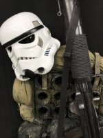
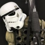
Update, Parade pic with some other Rogue One kits. Mando Con Crawl pic. Well DragonCon has passed and trooped (for the first time ever) my kit with the Crystal Patrol Pack for the parade. This was my first troop in this kit and I had some issues with the kit that I will detail here: 1. I needed to remove the thermal detonator from the back belt because the pack was pushing down on it and was causing the back belt to come off. Luckily, I realized this before the parade and made the adjustment. Thank God I made the thermal detonator removable. 2. Even with the added felt strips to the pack frame I still experienced some damage to the back plate. 3. One of my biggest concerns about the pack was that it would damage the armor shoulder straps but that turned out to not be an issue at all; however, when I packed all the armor in my transport box to take to DragonCon, I must have failed to pack everything correctly. When I unpacked everything in the hotel room I realized that one of the shoulder straps was cracked and the back plate on the left shoulder under the shoulder strap had cracked as well. 4. I had planned on getting a touch-up pin for the white paint I used but forgot to do so. When I noticed the crack in the armor and was already at DragonCon, I had a repair kit with me but no paint. 5. The backpack and pauldron worked out perfectly and took no damage at all. I even snagged the antenna a few times getting to and from the parade and the fishing pole held up great. 6. My left lower leg kept rotating outward. Even when I added Velcro inside the armor and sewn some on the boots, the Velcro simply detached from the armor and did nothing to hold the leg armor in place. I noticed the industrial strength was not staying stuck to the inside of the armor before I headed to DragonCon and I even used some non-sticky backed Velcro that was glued inside the armor with CA glue and that still came off. Not sure what to do to fix this issue. 7. Industrial strength sticky-backed Velcro failed all over the armor. Most of the time is came loose when it was stuck to a non-painted surface like the inside of armor. In these instances it was applied to the primed side of the armor that I did not coat with the flex seal. It seem to stick just fine at my house but in 90 degree weather with 100% humidity, it came loose in a lot of places. Not sure how I will address this either. Ok, so here is my damage assessment of the armor: The cracked left shoulder on the back plate, damaged in transport. The arrow shows that the crack continues under the shoulder strap. The right shoulder strap cracked during transport. I had CA glue in my repair kit but no paint. I found some white finger nail polish at CVS and used it over the superglue. It worked in a pinch but I need to get a touch-up paint pen. The damage to back plate from wearing the backpack. Paint worn off in several areas. I kind of expected this but I will need to add some foam to the pack frame to keep this from happening in the future. Left thigh experienced paint being worn away near the top front. The red circle is my attempt to cover with nail polish. I think this is being caused by the drop boxes or possibly if I bend over, by the belt boxes. This is a crack on the side of the left thigh. I actually did this a few weeks ago when I experminted with sticking my cell phone inside the thigh armor but I bent down and cracked the armor. The cell phone survived but the armor didn’t. I tried to use nail polish on this before the parade. Right thigh, same kind of paint wear. Left gauntlet paint wear, no idea what caused this. However, I did have issues with the gauntlets rotating on my arms. Not sure how to fix this. Right bicep paint wear in the armpit area and side. I guess this happened from just rubbing on the side of the abdomen. Similar type or wear on the left bicep as well. Right thigh cracked along the front cover strip. Since I do not open and close this part, I think this is caused when I squeeze the Velcro on the back closed. Right lower leg cracked on side of the front and again I think this is due to opening and closing the armor. Also notice the arrows point to paint damage. Right lower leg cracked along the front cover strip. Most likely due to opening and closing this part to put it on and off. Outside the right side lower leg paint damage. Also notice the Velcro that detached from the inside of the armor. Almost no adhesive left on it. Back cover plate, lots of paint damage. I guess this is just the back plate rubbing on it. Cod piece paint damage from under the front box belt. But plate cracked in two places. Abdomen plate cracked along front and paint worn. Possibly from wearing too tight and rubbing from chest plate. Abdomen plate worn on both sides along the top rim. I think this was the bicep armor. Right side outer box on the front belt. The bottom rivet has come loose. The thermal detonator before I took it off. This must have been the back pack frame. Lastly, those $65.00 gloves from Imperial Boots busted seams again. I am not happy with the quality of these gloves and will be contacting IB. So, I have my work cut out for the foreseeable future. Some of this stuff will be touch up but some of it will require more extensive repairs. Overall, I am not a happy camper. A $1,200 set of armor should not be this damaged from one troop. Granted it was parade, but come on, I am in the process to getting a full vacuumed formed rogue one kit and we will see if it holds up better. That’s the update, thanks for the interest.
-
11B30B4's RO T-21 Build (MkI -MkIII)
11b30b4 replied to 11b30b4's topic in MiniMag PTL Missile Launcher, T-21, RT-97C (MG-15)
Update, Ok so DragonCon is over and I am back on the T-21 project. I may need to work on my TK as well. The TK kit experienced some damage during the parade but more about that in my TK build thread. Ok so I concentrated on the feed tray. First I cut off the three hex bolt heads and I will be replacing them with round head (rivet looking) greebles I also cut off the lip towards the front of the tray and cut down the tabs on the sides of the magazine cylinder. After sanding here is how it looks before I add the greebles. I will be adding a shorter lip where I cut the original one off. I am also looking to add the roll markings on the feed tray but I have not tested how I plan on doing this. I do not have a steady enough hand to scribe them myself. One Idea I have is to make a template and sand blast them on but I do not know if the basting with cut them into the resin deep enough to be seen so I will need to test this. Last resort is to just paint them on. We will see what works out best in the future. Next, I primed the barrel shroud parts and assembled them. Since I planned on glueing the 2.5” pipe into the transition, I needed to install the sling mount and tactical light rail during the assembly to be able to access the nuts on the back side of the screws. I will be building a 1.25” sling so the sling mounts needed to be 1.25” (32mm). I had a spare AK-47 sling mount for this and it fit perfectly. I also had a small rail mount for a bipod that I cut down and drilled holes in to mount it to the side for the tactical light. All this installed and mounted the 3” collar at the transition and glued everything together with E-6000. I clamped it all together and let it sit for 24 hours. I also cut a horizontal line on the feed tray to replicate a separation in some parts but I forgot to take pictures of it so I will add it later. And that is the update. Thanks for the interest. -
11B30B4's RO T-21 Build (MkI -MkIII)
11b30b4 replied to 11b30b4's topic in MiniMag PTL Missile Launcher, T-21, RT-97C (MG-15)
Update… Well Imgur was down yesterday so I could not post pics from Monday until now. Ok so I sanded primed and painted the chamber tubes. Here is a test fit of the bolt already painted with metallic silver. So for the barrel parts and getting the desired milling lines effect. Looks like 80 grit sand paper used on the barrel while it spun on the lathe did the trick. Here are some pictures of the 2.5” conduit tube. And the 3” barrel tube. Barrel parts, I still need another collar, possibly two. As you can imagine, the lines in the tubes are not very deep so I do not know how well they will show once the parts are painted. I may paint them then re-sand them then apply a final paint job to bring them out more. I decided to cut down the outer edge of the cooling fins to allow them to drop inside the 3: barrel pipe. I made the top adjustment knob for the rear sight out of two brass lamp nuts, a small piece of lamp all thread, and a smaller nut that is adhered inside the all thread with PC-7. Once it is cured, I will sand and see this will work. Ok so I have been doing some research and discovered these pictures of aerial Lewis Gun configurations. I am thinking that the tall sight on the Rogue One T-21 is a modified Aerial gun sight. This first picture is the sight I think I will attempt to replicate and modify so that it is not as tall. The rest of the pictures show the vast array of sight options that were used in WWI and WWII. Another thing I am taking into consideration is that most, if not all, the weapons used for Rogue One were built from airsoft guns (E-11, A-180, A-280 CFE, DH-17, DL-44, A-300, MWC-35c, SE-14r, E-11D, DT-29, E-22, etc…), so was there an airsoft Lewis used to make the T-21 and if so, which variant of the Lewis was it? The Uk had Mark I through Mark IV versions with 4 different types of the Mark III. There are other version of the gun as well such as the US versions the M1917 and M1918. To complicate matters, there were other versions made for other countries. Soooo, the version of the gun used would shed some lite in some of these noticed changes from the OT T-21s like how the sling attaches and possibly the sights. Additionally, the configuration of the barrel collars is of interest to me. Different versions of the Lewis had different collars at different points along the barrel shroud. Well that is it for the update. I have DragonCon starting tomorrow so it will most likely be next week before I can make an additional progress on this build. Thanks for the interest. -
11B30B4's RO T-21 Build (MkI -MkIII)
11b30b4 replied to 11b30b4's topic in MiniMag PTL Missile Launcher, T-21, RT-97C (MG-15)
Ukswrath, were you able to glean any further details? I would really like more information about the shape and design for the big sight midway down the gun. Update, Ok so let me first say that before I started this build I did message Hyperfirm twice about pricing for a Rogue One T-21 with no reply. I figure they would be around $300.00. So based on that price, it is questionable if I would have been better to just buy one. After the $100.00 Spool86s kit, the knock off surefire scout light $40.00 and all the stuff I got from Home Depot and Lowes $200.00 ish I am already over the $300.00 price point; however, I get to build something and that cannot be quantified. Ok so here is Spool86’s kit and me doing some test fitting. I will say that I am glad I got this kit however, there are some things that I wish to change about the kit. I am basing my build somewhat on Yosh’s build and like him, I will be modifying Spool86s kit. Spool did an amazing job with this kit and nothing I say here should be interpreted as a criticism of his kit in any way. Test fitting the kit, I learned a few things. First the cooling fins seem to be sized for 3” (thin walled) waste water pipe rather than cellular core schedule 40 3” pipe. Both pipes have a 3” inside diameter but the outside diameter is different. Here you can see the cooling fin is not large enough to cover the edge of the schedule 40 pipe. The opposite seems to be the issue with the muzzle fins. Here you can see that the outside of the fins are larger than the inside diameter of the 2.5” electrical conduit. Looking at several reference pictures of an actual Lewis, I decided to cut down the feed tray. So one of the priorities I have set for this build is to make it as lite as possible. I may, at a later date, make a mold and cast this in rubber but for now, I wanted to just get it built and be as true to what I want as possible. So for the main support I chose to use ½” sanded plywood. I had considered several other options like making the center out of fiberglass or using a solid piece of wood but the strength of plywood cannot be questioned and it is hard to come up with something that is as easy to work with and as strong without it weighing a lot more. So I got a 2’ x 2’ piece of plywood and using panadatroopers template, drew out the shape. I decided to cut down the side receiver parts from Spool86s kit and make the chamber and bolt parts from PVC. This reduced the weight of these parts by about ½ and allows me to make the bolt look more realistic. Laying out the parts on the center support, I noticed an issue. If I stick with the schedule 40 pipe for the barrel, the cooling fins will not line up properly. On the bottom they look good. However, on the top the fins are not tall enough (red circle). Also because I cut down the feed tray, the center section of the support plywood is now 3/8” too short. So back to the hardware store I went and I purchased another 2’ x 2’ piece of plywood. I also picked up a 10’ section of the 3” waste water pipe. Home Depot did not have the pipe but Lowes did. So I retraced the support on the plywood but this time I added to the height of the receiver (where the feed tray would sit) and made a few other tweeks. Unfortunately, the 1” spade bit that I used to make the trigger opening bust out the bottom of the trigger guard. Honestly, I did not have high confidence that this thin section of the plywood would hold up for trooping so loosing this is not a huge deal. I had some ¾” wide and 1/8” thick aluminum in my shop so I needed to fabricate a trigger guard. A lot of cutting, bending and sanding later I had something that would work. Here is a side by side comparison of the 3” waste water pipe (Left) and the schedule 40 3” cellular core pipe (right). As you may expect the thinner pipe is liter by about ½ the weight. So no brainer, I’m going with the thinner walled pipe. I cut down Spool86s trigger. I routed out the insert of the support plywood and mounted the trigger with a spring. I also figured out how I would mount the trigger guard. A screw on the forward part and a nail (top of picture) used as a pin in the grip area. And around this time I was banging my head on how I would make the transition from the 3” pipe to the 2.5” pipe. Most people do this with a buildup of bondo but I wanted something different so I built a 3D model of the transition. This model is designed to be a sleeve that will fit inside the 3” waste water pipe and the ¾” wide collar then the 2.5” pipe slides into a channel at the other end of the transition. I designed this to only work with these pipe sizes: Waste Water 3” pipe ID 78mm OD 82mm Barrel Collar ¾” wide ID 83mm OD 89mm 2.5” Electrical Conduit ID 62mm OD 73mm The transition will be 60mm tall when assembled with a top opening of 73mm and the bottom opening of 89mm. So for anyone who wants this transition, please understand that it is still a work in progress; however, it is available for free download on my Thingiverse page. https://www.thingiverse.com/thing:3070308 Here are some pictures of the transition. This is it being printed. Here is a test fit. The top. The side. So feel free to grab this model if you have use of it. Next I sprayed primer on the support then I went in with Bondo to fill some of the gaps. I also started the stock. I forgot to take more pictures as I built it but basically I used two pieces of 1” thick poplar wood. Poplar is a hard wood (but it dents easily) and it weighs less than pine or oak. So I traced out the stock on both halves of the poplar, then I routed out the insert hole for the plywood support. Next I routed out the center of the stock to shed some weight. I basically kept about ¾” around the edges untouched then routed about ½” deep from the center area on both parts. Then I glued and clamped the two halves together and let it sit overnight. Now I am shaping the stock with various sanding drums and sanders. The flashlight and D- gasket tube came in on Sunday. So in a previous post I said that I wanted to replicate the milling marks on the outside of the barrel like an actual Lewis barrel shroud. However, that was before I realized two issue. First, moving to the waste water pipe, the wall thickness is only 2mm thick and milling anything from the pipe will weaken it considerably. Second, the maximum length I can mill in my lather is 20 inches and this does not take into account the center and 3 jaw mandrel. So I would need to make the barrel portion 18” rather than 19” to mill it. Another issue I did not consider is that the PVC pipe would not mill like other plastics. It basically develops a rough “hairy” face on the area milled. This can be cleaned up with sanding but a lot of the detail of the tooling would be smoothed in the process. This is from one 18” pipe. And even after milling about 1mm (1/2 the thickness of the pipe wall) this is the only detail I was able to produce. This is a picture of the wall thickness of this pipe. So to produce the milling on the barrel, I will need to find another solution or drop the idea all together. Something to ponder. Well that is it for the update. Thanks for the interest. -
11B30B4's RO T-21 Build (MkI -MkIII)
11b30b4 replied to 11b30b4's topic in MiniMag PTL Missile Launcher, T-21, RT-97C (MG-15)
ukswrath, I see the stock color, flash light, sling and mounts, looks like a tall rear sight between the barrel and the receiver. What else do you see? -
11B30B4's RO T-21 Build (MkI -MkIII)
11b30b4 replied to 11b30b4's topic in MiniMag PTL Missile Launcher, T-21, RT-97C (MG-15)
Ok so here is another shot of the previously posted picture. The sling looks black to me and the stock does as well. Also notice that the sling is mounted with a sling mount in the front top side of the barrel rather than being wrapped around the barrel. In another shot (I have somewhere) of the same TK the rear end of the sling is also mounted to a sling mount that is mounted to the left side of the stock. Here is a shot I found that this T-21 has no sling and the stock does look to be slight dark brown but again it could be the lighting. Guys feel free in your copious amount of free time to find more reference pics from Rogue One of behind the scenes pics that have T-21s in them and post them. I am unsure which direction to go with the stock and may settle on an Ebony stain for the stock. Spool86’s parts are hitting my mailbox today so I should get started on building this thing this weekend. For the barrel I like what Yosh did with his build and just about everyone agrees that the PVC pipe is the heaviest part of the T-21; however, I think I may have an idea to sue the PVC pipe but lower the weight. I am hoping to put it on my lathe and take about ½ the weight down by cutting the groves in it like the actual Lewis barrel shroud (red circle). So that is it for the update. Thanks for the interest. -
11B30B4's RO T-21 Build (MkI -MkIII)
11b30b4 replied to 11b30b4's topic in MiniMag PTL Missile Launcher, T-21, RT-97C (MG-15)
Thank you -
11B30B4’s RO Crystal Patrol Pack Build
11b30b4 replied to 11b30b4's topic in Rogue One Build Threads
Ok guys, I have started a build thread for my T-21 here: -
Ok guys, I have started a build thread for my T-21 here:
-
So this is where I will be logging my T-21 build for my Rogue One Kit. Not a lot of stuff at this time but I am sure I will be filling this thread in the coming weeks. So first let me say that I will be using Spool86's kit. NOTE: Version 2 of the RO T-21 is on page 2 of this build. For anyone interested, my ROTK build is here: And my RO Crystal Patrol Pack Build is here: There are a few difference with the RO variant of this BFG. 1. There is a scout tactical light on the right side like a lot of the RO weapons. 2. I have found reference pictures with a black sling and pictures with no sling. 3. From all the pictures I have found, the stock looks black but this could be the lighting. Here is a pic with the black sling I will add more pics tomorrow but I wanted to get this thread started. I welcome input from everyone. Thanks for the interest.
-
Dude, that build is epic. I really wish you had logged all the build pics and what you were doing here as you worked on it. Hands down, the most detailed T-21 I have ever seen. Job well done.
-
11B30B4’s RO Crystal Patrol Pack Build
11b30b4 replied to 11b30b4's topic in Rogue One Build Threads
DEVOLVER, thank you and I look forward to seeing you build the pack. Mgb1016, So I am not sure what type of straps you are using but the process must be similar. For the RO Crystal pack we use the LC-2 Alice USGI quick release straps. The top straps are simply wrapped around one of the top bars and then secured with a ladder-loc slider. The bottom of the straps are secured to the corner 45 degree frame members. The strap is wrapped around its self and then pulled tightly. I hope that helps explain what I did. Good luck on your build. -
gmrhodes13, thank you. Ok guys, well I assume that most if not all of you noticed the site outage over the past week? I was not complacent during this time. I started and finished my Crystal Patrol Pack. I would have preferred postings daily and you guys providing feedback but that would have been impossible since I could not post anything about the build on the site. I did log all my activity and post it here: https://www.whitearmor.net/forum/topic/45419-11b30b4’s-ro-crystal-patrol-pack-build/ And here are a few pictures to entice you. Next I will be starting on my T-21 and I will link the build on this thread as well.
