
Helotech
-
Posts
427 -
Joined
-
Last visited
-
Days Won
3
Content Type
Profiles
Forums
Gallery
Articles
Everything posted by Helotech
-
 One other thing: I MAY have some small hardware bits (screws, rivets, etc) or extra leather for the holster. I'll check my spare parts box. Let me know if you can't source it when the time comes.
 -
Hey! For the calves (and other armor parts), make sure you don't trim all from one side of opening. You want to trim equally from both sides, and how much you trim depends on the size of your calves. I ended up with about 1/2" from the molded in raise area to the cut. I found the easiest way to cut is with a Dremel on slow to moderate speed, but this sends bits of plastic flying. Make sure you wear a mask and eye protection. Draw a line with a pencil and cut as straight as you can. You can also scribe and snap but this is harder because of the curves. These cut edges now butt up against one another. To make the cover strip, I used the rear part of the belt. You have to get rid of this anyways, so don't be afraid to cut it into strips. I'd suggest using this plastic as it is the same color of your armor, so a color shift with other white plastic won't be noticed. SDS armor has a very nice light cream tone, while other manufacturers almost use pure white. For the rear cover strip (25mm), measure exactly 12.5mm down the middle of the back side and draw a line with a pencil. Place some E6000 glue on one side of the line and clamp it to the correct piece of the calf. Make sure you clamp to the correct piece!!! The 12.5mm overhang now receives new velcro. Let me know if you need any more help. And good luck!!!
-
Congrats and well done! EI and Centurion are not that much more work.
-
Sorry, haven't been in the forums for a while. Glen answered best (as always!!!!!)
-
Hey Jacob, Glen linked to my build of the SDS. I basically ordered the suit as it was the first thing in my google search and was very naive. It is expensive, but without having personally compared it to other manufacturers (except quick side by sides at various troops) I would say it is worth the money to me. It is accurate in shape (as far as I can tell) and seems to be the proper off-white cream colour. There is a noticeable difference when I stand beside someone in a stark white TK armour. SDS does come pre-assembled but is not approvable out of the box. You have to almost take apart all the pieces (not that hard), possibly trim a few, then reglue. Depending on your skill level it is very easy to do and there really isn't that much that is required. I believe the only downside is the added cost and having to order some things like belt fabric pieces, rivets, screws, other hardware, etc. Other makers may include this stuff already? In my opinion it is better than having to trim individual pieces out of plastic sheets. However, some other manufacturers sell all the pieces and all you have to do is glue them together. So basically, the choice is up to you. If I had to do this again, I probably would have gone for another manufacturer and start from scratch simply due to cost alone. Let me know if you need anything. Dave
-
Hey Greg! I was in the same boat. I ordered SDS before knowing the history of "issues" with the company. That being said, the SDS kit is actually very good. I'm not one for the politics of the controversy. I receive a ton of compliments on my armor. It will take some work, but I believe it is less hassle than having to scribe and cut parts out of ABS sheets. Let me know if you have any questions. Looking forward to your build.
-
Thanks for the shout-out Glen! Here to help if yo have questions.
-
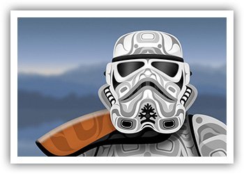
Idealized Stormtrooper Helmet Build
Helotech replied to ChaoticAmanin's topic in The Foundry - Armor and Prop Making
Sorry to hijack the thread, but I am designing and printing a helmet interior kit based off your first photo with the black background. Not the blueprint version. You can see my progress in the 3D printer forums: -
Well, I finally got it done! I was supposed to get this ink in march for my 50th, but the artist had to cancel. So we rebooked for May 4th, OF COURSE!
-
Thanks for the continued shouts out Glen! Matt, if you need any help with the SDS, let me know. After all was said and done, i think reworking the SDS was much less work than an unfinished kit that you need to trim from plastic sheets and assemble from scratch. Yes, updating needs to be done to get it approved, but I get many compliments on my armour. Good luck, and I can’t wait to see the final product!
-
And some final pics for this thread. Until I can build my blaster rack, I needed a way to display the DLT. I bought some padded tool U shaped hooks from hardware store, drilled them into conveniently spaced wall studs, and hung the DLT. I now am sourcing a good case for it so I can bring it to troops without raising eye brows in hotel lobbies...
-
YouTube video link is on page 2. 4 videos in a playlist. Commentary is last and longest one.
-
I’ll do a build thread for that.Not sure if I’ll keep it here or on another forum page, but I will link the two together. I’d like to get it done within a shorter build period so it doesn’t drag on for ever like this did. Just running through ideas in my head at the moment on how it will look. I would like another DLT to fill up the rack, but there is no way I’m doing another filament printed one like this! Too much work. The second DLT would strictly be for display, not trooping. I did find very good files to 3D print a MG-34. That is where I got the cocking handle file for this build. However, I only have a small resin printer at the moment, so I would have to cut it into lots of smaller bits, and it will eat up allot of resin. I would also have to source tubing of correct diameter for barrel shroud, etc. The wife has authorized the purchase of a larger resin printer, and my 50th B-Day is coming up, so you never know….
-
Yup! That is my inspiration. I have that page bookmarked. I was going to make a combo blaster rack. I currently have my DLT, 4 E-11’s (various stages of doneness) and my SE-14 and will want to put them on the same display. Kind of like it would be in a security room. A grab and go rack. All my wood working tools are in my unheated shed at the moment, otherwise I would start. At -20 C there is no way I am working out there!
-
Thanks Tino! This was definitely a labour of love. The printing was typical filament layers and took quite a bit of sanding. I now have to make a stand or display mount for it. This summer I will try building a blaster weapon rack, similar to the one seen in the Death Star Security office, so it can be displayed beside my armor.
-
Thanks Jonas! Glad you like it. Trust me, I understand being busy. This took almost 2 years to finish, but it was worth it. The kit is great, but if I had to do it again I would spend the money on one of those new Denix MG-34's and just add the blaster details. Way less headache LOL Fortunately / Unfortunately, now that I have this project out of the way it means I now have to start on my new metal E-11 (with Blast-FX ) and my Boba build. I am such an idiot.... Can't wait to see your build,
-
At long last it is done!!!! I finally managed to grab some pics and videos of the final build. Youtube link to 4 videos will be posted at the bottom of this post (hopefully it works...). One of the videos has my commentary. Other ones are just showing the blaster and me pew-pewing with it, as well as the lighting effects of the barrel in a darkened room. Please bare in mind I am not a photographer or videographer, so be kind. I touched up some of the paint from doing the final build steps. I then clear coated everything in a Sem-gloss paint from a rattle can. This ended up being to shiny, so I went over everything again with Tamiya model paint dull coat. Everything except the shiny rings between the butt and receiver, and the butt itself. Enjoy... Over all shot. As you can tell, I am using the gun vise and not using the blaster bi-pod to support it. I still don't trust the bipod due to the cracking issues I had before. Each leg seems to flex when I tried to rest the blaster on them. Loving that side box paint job! My scratch built display details, as well as the fully functioning fire selector switch. Main and scope displays in the modes that I like, as viewed by a gunner. There are several different options for each display. Details of the bottom barrel T-track wires and pigtails. Of course, once all this was done I then found a new to me screen grab pic that of course shows the wires not at the end of the t-tracks, but more away from the edges. You can see the barrel wiring through one of the holes. Small sticky sided velcro strips that are required to hold the bipod up in retracted position. They can't be seen when the bipod is swung up. Velcro on the "Bipod Hold open knubbly conical bolt device". That is my official name for it... Underside of the receiver. The opening is where the main display would normally be. Not very useful or ergonomic for a DLT gunner checking on his ammo count... That is why I made my own. This is a separate panel that you can replace with another provided panel with no holes in case you aren't installing a Blast-FX. Just forward of the opening you see the sliding ON / OFF switch for main power. Forward of this is the button that you press momentarily to cycle fire modes (as opposed to using the grip circular switch). Or you can hold it down to enter the Blast-FX set-up mode, that, in conjunction with the trigger, allows you to change sound and lighting options. The main circuit board memory stick of the system has sounds for most weapons used in the SW universe, as well as ship sounds! It is funny having a blaster that emits the sound of a TIE fighter or the Millennium Falcon each time you press the trigger. LOL Internal wiring and battery compartment with the receiver cover lifted up. You can see my resin 3D printed cocking handle. The screw did not come out when I started unscrewing the handle for transport. One last thing to fix. Video Link: I made a playlist with 4 videos. Maybe was a mistake? Anywhoooooo, if you click on the link all 4 will play back to back. Just fast forward them. sorry. My longer video with commentary is the last one. One or two of my pups show their faces
-
If you can’t find sheet metal for the side box and aren’t picky about being tru to the movies, you can use good plastic sheets available at model stores. Maybe even clear acrylic sheets available at home improvement stores. I just finished my DLT and will be posting pics and video soon. Love the display mount
-
A bit more work done. Tubing installed in the blaster. T-Tracks from Wannawanga trimmed and installed. I just used the DLT Blaster images and tried to replicate the correct angle and small groove the wire sits in: Original and trimmed length. Wire I am using for the t-tracks. It is "Lock-wire" used on Jet airplane engines to prevent bolts from loosening. Being a former aircraft technician and learning skills like lockwiring has it's perks... It's even a suitable dark grey colour that won't need to be painted. T-tracks glued on with E-6000. Lockwire is then tightly wrapped and secured using what we call a pig-tail twist. This was trimmed then tucked away out of sight on the bottom of the barrel shroud. Front and rear barrel sections with everything installed. It was at this point I remembered I had to replace the barrel locking lever piece that fits in this groove below the circle. I lost it at some point during my move across country... You can also see the laser poking out of the side box (bass piece.) I just painted the outside of it black. Scrap plastic cut and trimmed and sanded to fit. Installed but not glued in yet. The front portion (towards left of picture) has been trimmed and rounded slightly to match reference pics. I also cut some grooves at the front that provide grippy texture. That's it for now!
-
Updates! I've had continuous issues with wires snapping on the speaker, rotary fire selector switch and laser. This happens with me doing minor manipulation to fit things into the blaster. I wish the connections were reinforced somehow. Anyways... Small white plastic piece cut and fit in front of main display to hide wire connections. Small rivet /buttons used as replacement hardware for grips: Hardware installed Grip installed. I actually had it screwed on with the grip panels installed. After each component installation I check the wiring. It is now that I found the rotary switch did not want to switch to automatic / burst mode. I had to take everything apart and found one of the 4 pins to the rotary switch was loose. When I jiggled it all 3 fire modes worked. I took everything off, fixed the pin, and then reinstalled everything, including gluing down the grip panels again. Unfortunately, now only one fire mode works. I checked inside the top of the fire selector (inside the receiver) and two of the wire connections have snapped. Grrrrrr. Will be fixed... Grip in and screwed to receiver with more correct hardware. I also replaced the grip panels screws. These will all be painted. During these final builds I have added minor dings or scratches to the blaster. I will be repainting where necessary, then weathering and clear coating it all. I brought up my Tipton gun vise to help me do the final installation. It's made things easier than having the blaster flop around on my desk. Here you can see I've installed the lens for the scope display. It's hard to make out in this photo, but I glued on a small piece of plastic to cover the main displays wire connections. You can just make it out below and to the right of the lens. I will be repainting this as I just did a quick brush coat of flat black. You can just make out the wire bundles in the receiver. There is just enough room to slide the main circuit board and wires inside towards the barrel. You can also see a USB cable poking out which I will explain below: Another view. To get power to the blaster, I had to rig something up. To power everything I am using a 3.7V 2000mAh battery. This has a small white connector (type?) attached to the leads. This is connected to a Powerboost 1000 Charger (circuit board with Blue LED). Just youtube this component and the company explains what it is all about. Both will be inserted into the receiver in space above pistol grip. The battery is charged through a Micro USB connector from home outlet. This of course is only connected when you need to charge the battery. This way I don't have to remove the battery to charge. I just open the receiver cover and plug the system in. The blaster main circuity board comes with simple black and red wires coming out of it. Before discovering the Powerboost component, I originally was looking at adding a male connector to the BlastFX black/red wires so the battery could be plugged into it. But then I would have to disconnect the battery and charge it somehow. BlastFX also provides a small sliding on / off switch so you don't have everything powered all the time when the battery is plugged in. In order to get power from the Powerboost to the BlastFX, I needed a USB type connector. I have a few of basic USB wires laying about (everyone got a junk drawer, right...? LOL) After a quick google search I discovered USB cables have 4 wires : Red, Black (power) Green and White (data). You only need the power cables. I basically removed the outer cable sheathing, exposed the wires. I then cut the green and white off and used black and red. Scrap USB cable. I only kept the USB connector (top of photo) and cut off the mini plug. Cable ready to go. White and green were trimmed off. The insulation from the black wire has already been removed. When I attached everything as you see in the diagram below, I can now leave everything inside the receiver and just plug it in when required. Once I'm done I may do another diagram like this showing where everything fits in the blaster. So, being the gun guy that I am, I of course wanted the included laser to be aligned with the gun sites. The setup: Laser installed in a hole I drilled in the receiver side box. Wire runs through the box to the BlastFX module. I temporarily installed the front sight/bipod assembly and aimed the blaster down the hall leading to the kitchen. I then placed a small piece of electrical tape on the front closet door. The gun front and back sites are actually lined up with the tape. Aiming down the blaster, with laser on the far wall. You can see it's slightly off. After a little fiddling I could get it to move. I pulled the laser out, dabbed on a couple drops of E6000 to the sides of the laser module and reinserted it into the blaster. I then used a small tool (second hands, soldering clamp with small alligator clips?) to grip the laser and manipulate it until the laser was aligned with the blaster sites. This is the tool resting on the receiver. Alligator clip holding the laser in position while glue dries. The laser module sticks out of the blaster by about 1/8" A little better... One more nudge and pretty close! Now at least my TK will hit those damn rebels and and avoid those "Stormtroopers always miss" jokes! Last little bit was me trying to sort out the LED laser barrel strip. This is the strip hanging out of the opening I cut in the barrel. The group of red / black wires lead to the LED module in the barrel tip (inside the flash cone) that produces muzzle flash. These were cleaned up into a tight bundle after this pic was taken by wrapping electrical tape down the length. I've seen people online insert acrylic rods into the barrels that make their LED effects "glow" better somehow when they activate. Not sure glow is the right term. Their lighting just seems more....gooder. LOL I can't get acrylic rod here, and wouldn't have room to insert it into the barrel. So to maybe help elevate the effects of my LED strip I am going to try a section of plastic tubing. I couldn't get a small enough outside diameter to fit inside the barrel tube. This roll is 1 1/4" outside diameter. I had to cut about an 8" length of a big roll. Then I sliced about 1/2 " lengthwise from this piece (end to end). It retained it's semi-circle shape and I could still squeeze it into the barrel in a tube shape. I then sprayed it on the inside and outside with window frosting spray from a rattle can. This would help defuse the LED lighting so it wouldn't be point's of light inside the barrel. More of a soft glow. I had a video for this, but can't upload it. I use IMGUR for my picture uploading, and can't figure out how to insert a video to that site. Are we even allowed to insert video into forum posts? I may have to upload to youtube then provide a link. We'll see, as I would really like to upload a video of the final blaster. That's all for now! Stay safe everyone
-
Awesome! Thanks. Not my cat, but just one from the YouTube video. I do have a cat, and will make sure to include him in another post just for your daughter He does look like this little kitten though
-
Baby steps. Unfortunately, work is getting in the way, so I only have time for a few small things. Fire adjustment rotating switch has been glued into the pistol grip. I had to sand and carve a square groove for the switch to fit into. The MG34 fire selector will be glued on top of this to blend it in. Hopefully it will then look and work like a real gun selector to go from stun, to semi, to auto fire. Vibrating "rumble" button glued into the grip. I had to re-solder and tape the connectors as...you guessed it... the wires snapped! The wires just up and to the left of this button go to the trigger actuator, Bad picture of the trigger micro switch. It is to the far left inside grip. It was hard getting this situated so it will be activated when pulling the trigger.
-
Some slow but steady progress. I had to add in a few wire extensions so components could fit where I wanted them. Attached the main display to gun. I still have to cover up the bit of circuit board you see closet to the receiver. I painted the little fake buttons with Tamiya metallic blue and orange paints for some visual interest. I also inserted the scope display and worked out a good distance to the lenses. They have to be at an optimal distance as the lenses magnify the tiny screen image. Just waiting for the scope display mount glue to dry. Here is the display inserted into the gun. The little white thing to the right is a small piece of scrap plastic I used as a tab or holder to manouvre the display inside the cavity. It doesn't need to be trimmed as it won't be seen when it is buttoned up. And yes, once it's all put together I will be posting a video.
-
Update: I had to de-solder the wire connections for the scope display, main display, and laser in order to feed the wires through their respective holes. My soldering skills aren't the best, but I managed. Once done, all the components were re-attached and tested. I then found out my speaker wasn't working. A quick check revealed that the wire connection had snapped....yet again... for like the tenth time.... I have mentioned it before that the BlastFX kits are amazing, but I have had a bugger of a time with wire connections snapping from simply manipulating components around the blaster. This is understandable as the wires are very tiny due to the components used, but none-the less very frustrating. When it comes time to install everything and glue the bits-and-bobs on, I will probably use E6000 instead of superglue. That way I can probably pry off stuff to get to wires if needed. In this picture you can see the red/black wire extensions with connectors that I made that go the muzzle lighting effects. This was so I could take the blaster apart into two main parts: Barrel and Receiver, for transport. I really want this to fit in my TK transport case lid so I don't have to lug around a big rifle case and get stared at suspiciously... I'll have to see if this is still feasible as the barrel is very hard to slide into the receiver, and as this is simply printed plastic I don't want things cracking over time. You can also see the battery (yellow) and at the far left, the white rectangle is the bottom ejection port cover plate and will hold the on/off switch plus the 3 mode fire selector button. (Single shot, rapid shot, stun). I will still be using the kit supplied rotary fire switch that is part of the pistol grip and replicates the MG34 selector. However, if this craps out, I have an alternate mode. Everything is now fed through the holes, and I am GENTLY starting to re-assemble the blaster. In earlier posts, you see how I cut out the barrel near the receiver in order for more light from the LED string to show through. After looking online I saw a video made by 3D Props (maker of my DLT) showing the lights more toward the muzzle. It looks great! Also, the spacing of the T-Tracks at the muzzle gives more hole openings. I'm not sure how he is accomplishing this with the metal support "barrel" than runs through the barrel jacket. There is no room between the barrel and barrel jacket for the LED strip. Hmmm.....? I was considering moving mine towards the muzzle, but I would have to extend the wires, an possibly drill barrel holes again, which is a pain. I'll just have the lights at the receiver and worry about it at another time. I've also painted the new printed components, and have to wire in the On/off slider switch for the power.
-
Do you have access to sheet aluminum and tin snips? If so, I can send you exact measurements of my 3D props blaster and you can cut your own. Then it is easy to cut, fold, paint, ang crazy glue it to the blaster.
