

Thrawn's guard
-
Posts
479 -
Joined
-
Last visited
-
Days Won
9
Content Type
Profiles
Forums
Gallery
Articles
Media Demo
Posts posted by Thrawn's guard
-
-
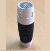
As promised in my earlier post here are a few shots of how I created the end cap clip.
This was another one of those little jobs that turned out taking longer than expected..............Though one that I have really enjoyed.
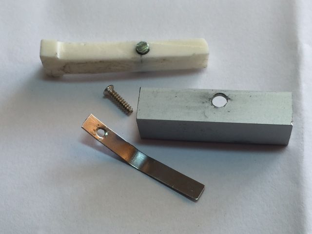
Firstly I collected together the parts that I intended to use.
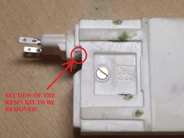
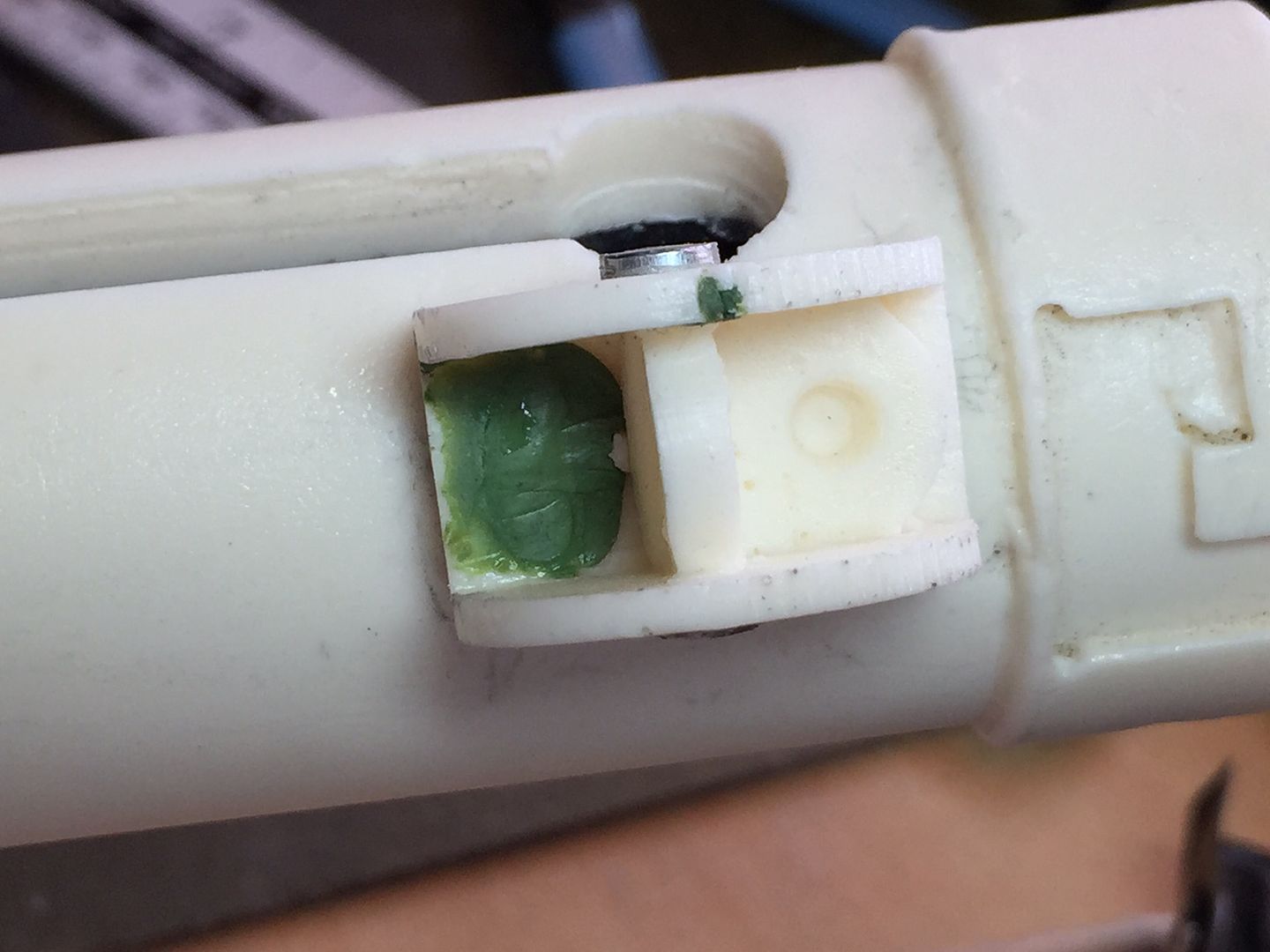
In order to have a functioning end cap clip I needed to remove the cast resin ‘tilt switch’ from the Doopydoos kit and install it in to the aluminium channel provided in TJ’s completion set.
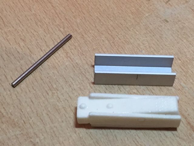
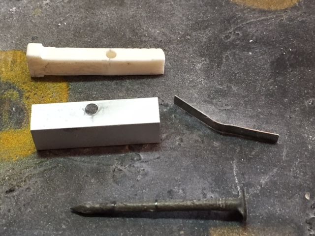
I decided to use some spring steel, as was used on the original Sterlings, to provide the spring action. Therefore I also took one of the springs from the counter shown on the first page of this thread and bent it in to the correct shape (The spring from the counter is shown below).
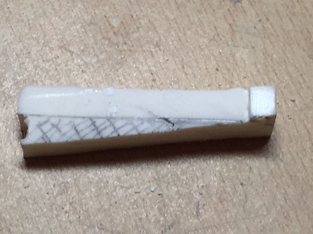
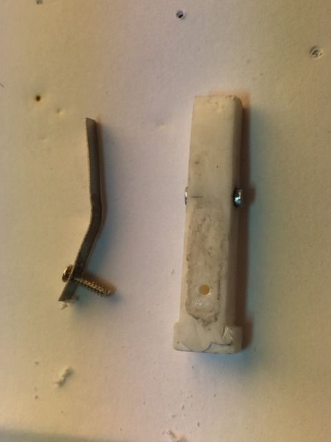
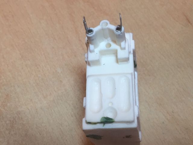
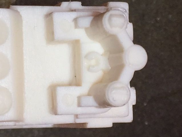
The first task was to remove the resin cast channel which was achieved by use of a cutting disk on a Dremel and also some fine nail files. Once this had been done I marked out the remaining area of the resin that needed to be removed so that I would be left with just the tilt switch.
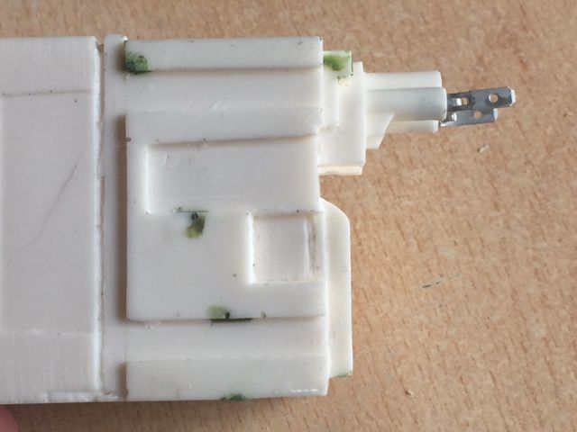
The tilt switch was test fit in the aluminium channel to ensure that it fit correctly.
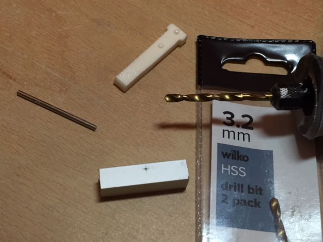
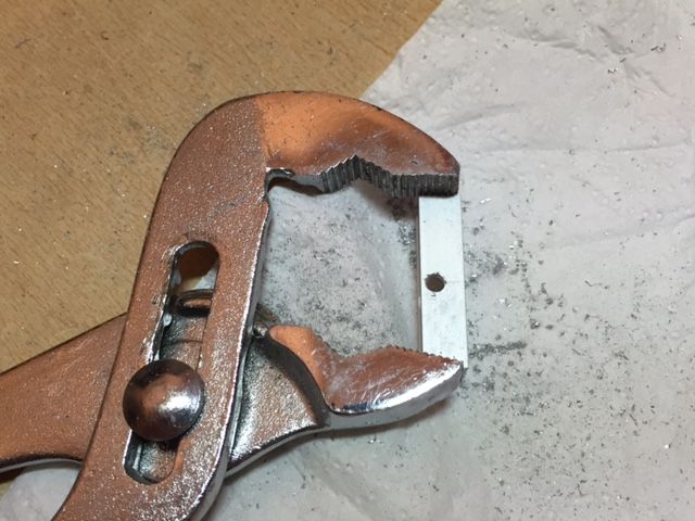
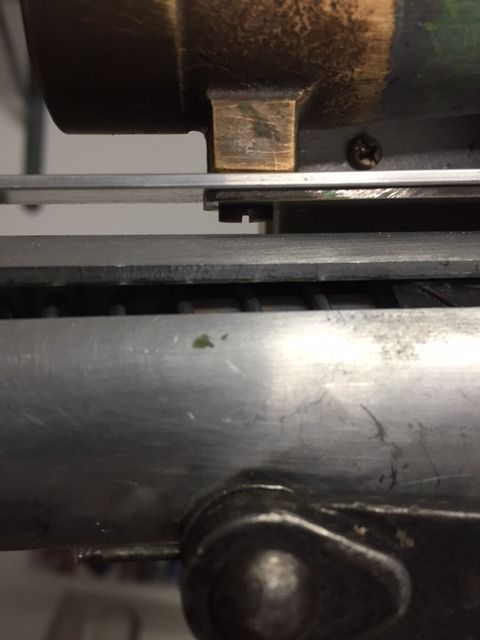
The holes in the 2 walls of the channel which locate the pivot pin were then drilled using a 3.2mm diameter drill bit. I held the channel in a plumbers spanner, (wrench), as I drilled the holes as the channel tends to get hot when the holes are drilled.
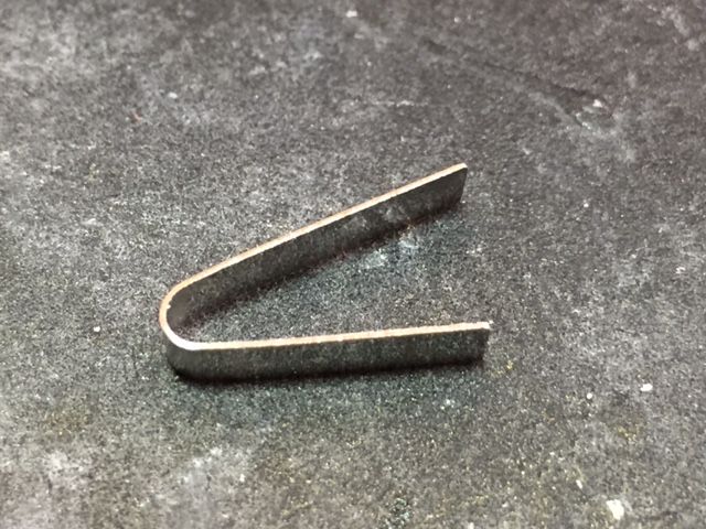
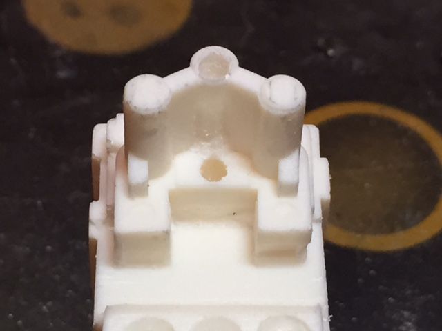
Once drilled I found a nail that fit tightly in to the holes in the channel walls. This nail was then marked up to be cut to length, (slightly shorter than the overall width of the channel), and would form the actual pivot pin. The spring reshaped in to the correct shape for the clip is shown below.
The most difficult part was actually forming a hole in the spring steel for the fixing screw to pass through (I didn’t have a suitably small drill bit for use on metal). However once cut the spring was located in the correct position and used as a template to drill through in to the resin tilt switch.
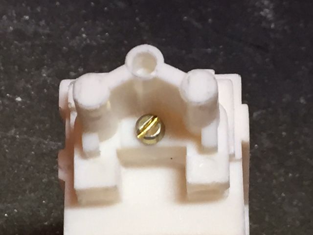
The locating screw had to be cut to length as it was too long. Glue was then applied to the spring and resin tilt switch and the screw installed.
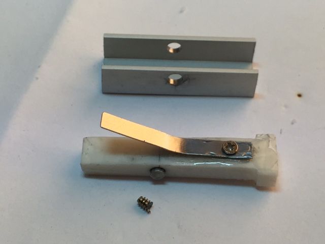
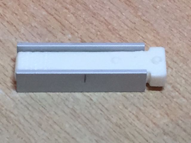
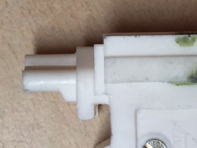
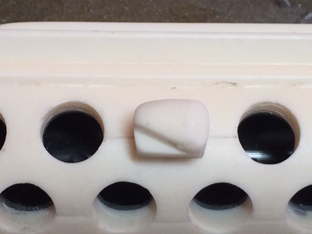
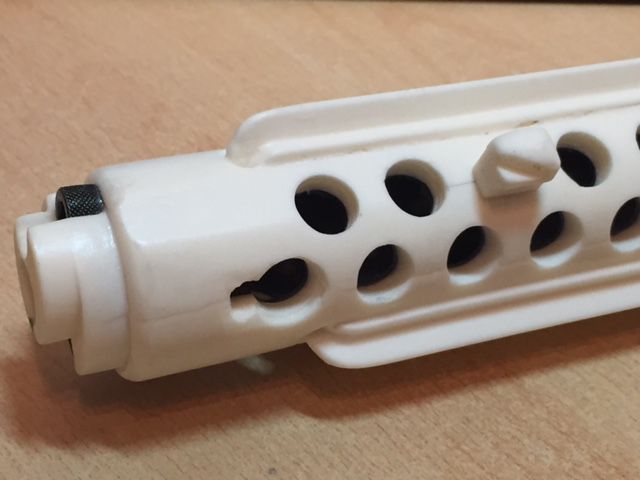
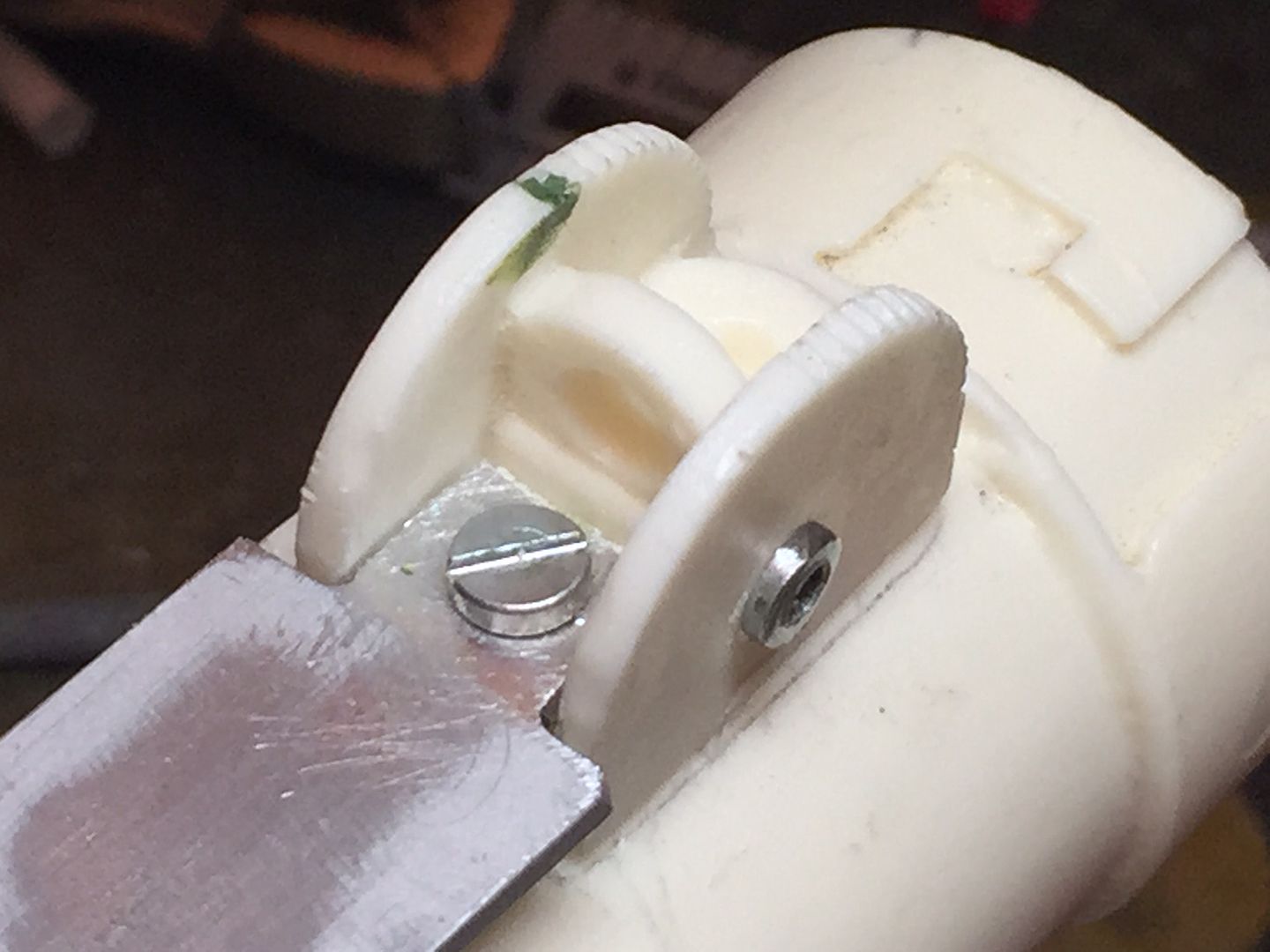
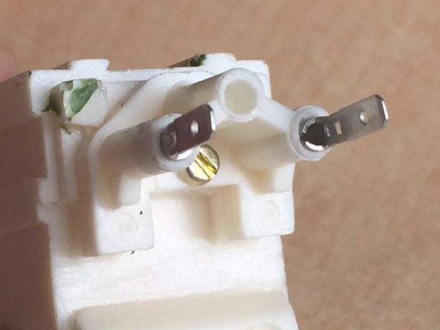
Once assembled this is what it looks like.
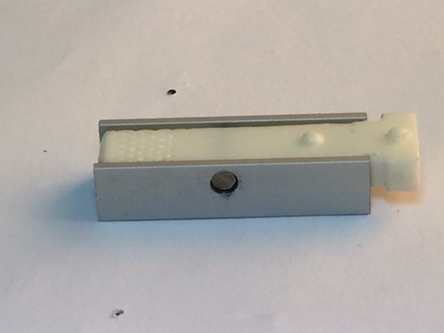
I will add the key on the end of the Tee section of the tilt switch once I have sorted out the end cap to ensure that all is located in the correct position.
-
 2
2
-
-
I'm still deciding if to make a blaster stand or purchase one but I must admit I think that the one you have bought looks fantastic and really presents the blaster very well.
-
1
-
-
I thought that I would post a quick video showing the end cap release clip that I have been working on.
I will show the steps involved later today.
-
1
-
-
Mike having double checked some reference pictures myself you are correct in that the screw located between the 2 electrical connector is a Phillips rather than single slotted type screw.Chris are both to the screws on the bottom of the counter slotted? Looking at some pics it looks like the top screw is a Phillips. I could be wrong... just looking at photos online.
From what I can see it is a Phillips dome headed, rather than countersunk, screw head of about 4mm diameter.
-
1
-
-
I've started work on the end cap clip and will aim to post some update pictures tomorrow.
In the meantime can I ask what peoples experiences have been with regard to the endcap ?
The Doopy kit endcap is very loose and will need some work to stabilise it. So far Bulldog's solution of incorporating rubber packs seems a good solution.
I may need to go seekering some suitable rubber sheet.
-
With the better quality photos the blaster looks even better.
-
1
-
-
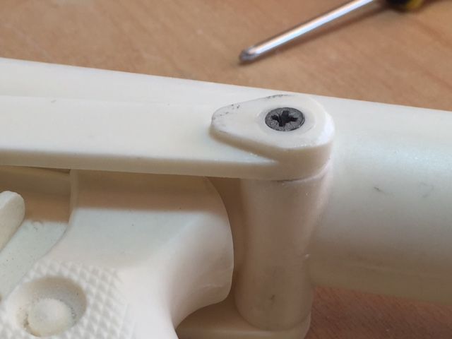
The next job was to turn my attention to the folding stock.
I carefully sanded off the resin domes on the end of the folding stock arms and then marked out the centre position on both the stock arm and folding stock connection on the receiver.
Using a 3mm diameter wood drill bit I then drilled out the hols for the fixing screws. I also had to very slightly increase the diameter of these holes using a Dremel bit as I needed the hole to be just larger than 3mm diameter but a 4mm diameter bit would have made the connection too loose). I never thought when I started this build I would intentionally start working to tolerances of less than 1mm.
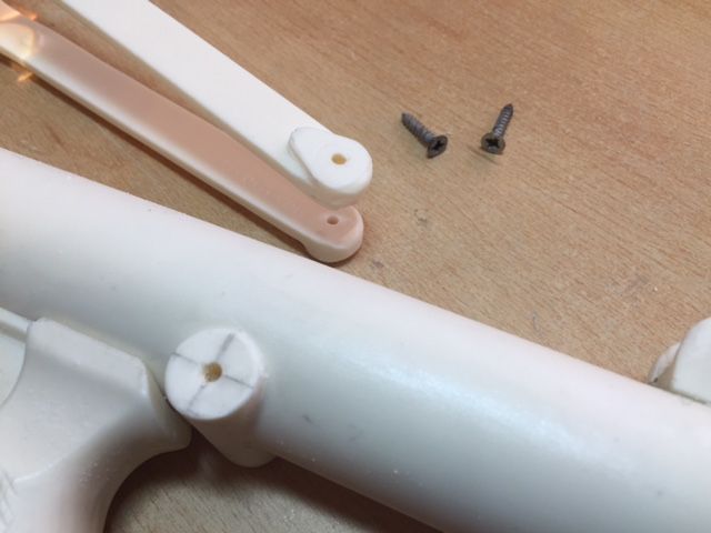
Taking a pointed Dremel sanding bit I then created a countersink recess to allow the screws once installed to sit flush with the folding stock arm.
Taking two upholstery nails, which provide me with a nice dome of the correct diameter, I measured the depth of the cross recess in the screw heads and then cut the pin section of the nail off with a cutting disk bit to leave a small projection just less than the depth of the cross depth.
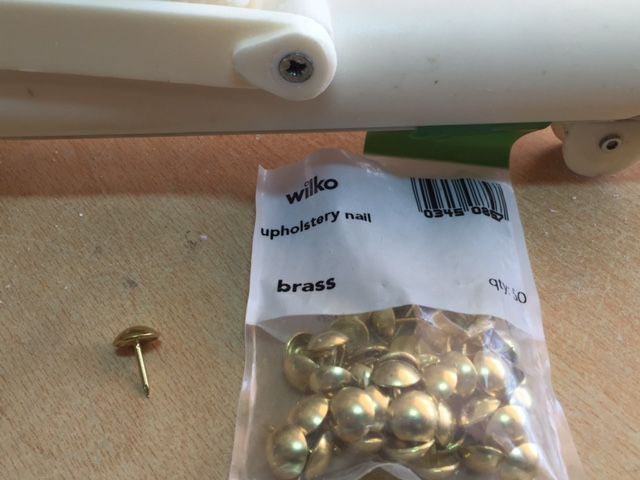
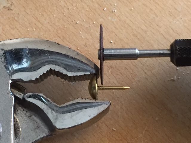
This was done so that once I install the dome heads I will have a small amount of mechanical key i.e. pin effect in addition to the glued joint to make it more durable.
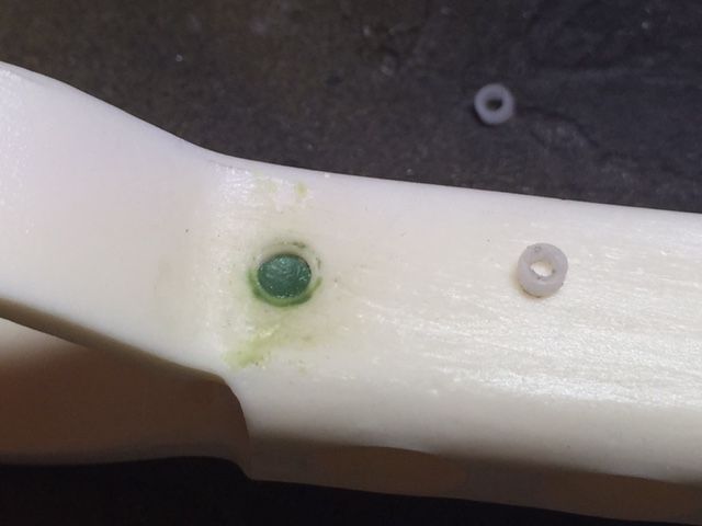
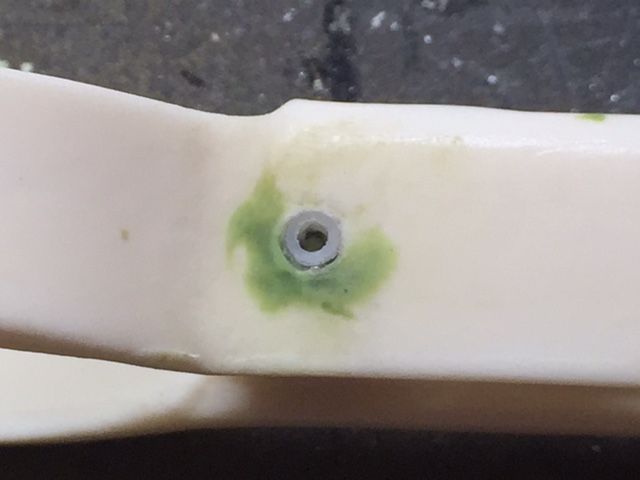
This is what it looked like when i had done.
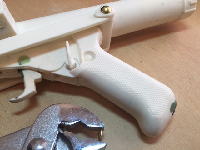
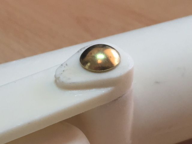
I will fill the head of the screw with green stuff and then glue the domes in to position later (I want to be able to remove the folding stock for now).
-
1
-
-
Dan glad to be able to help with regard to the electrical contacts.
By the way both the blaster and your stand look fantastic.
You've done an incredible job and all that effort has definitely paid off.
-
Richard I have never used green stuff to stick pieces together like this so don't know how strong the bond will be.
I will be interested to know the results but I would potentially be concerned that it may stick the two pieces together but the bond may fail if the scope is bumped.
Will you also have access to the inside of the scope as some green stuff will have squished out to the inside of the joint similar to what can be seen on the outside of the joint ?
If you can still get in I would use a knife or something similar to remove the excess before it cures.
In any event it is certainly worth testing as the worst case scenario is that the joint isn't strong enough and you end up glueing the two pieces together.
-
Hey Dan I'm not 100% sure what you mean here. Do you photos above answer your query ?The contacts on the counter are a mod I haven't done on mine, will have to do it sometime. Looks like I've got female spade connectors in my toolbox but not the male ones needed for this so I'll have to pop out and get a couple.
Did you also shave off the extra bit of resin on the side of the counter (left hand side when mounted on the blaster, facing outwards) where the two T pieces are joined next to the recessed square area?
Dan
I see what you mean now......Well now that I have read the past few posts. I think that I will keep it the way it is though if this proves to be not screen accurate it is a quick fix to alter if needed.
-
Looking good Chris. If you want to go that one extra step, which I know you do, you could do a bit more filing on the Hengstler, as got pointed out to me during my build. See post 221 below.
http://www.whitearmor.net/forum/topic/29089-dvh-pipe-build-with-extras/page-12
There's also some good images in TK-50101 Blue Snaggletooths for sale thread at the moment.
Back to the scope screw discussion - that one you have securing the rail looks pretty good! Can't tell what the diameter is, but must be close...
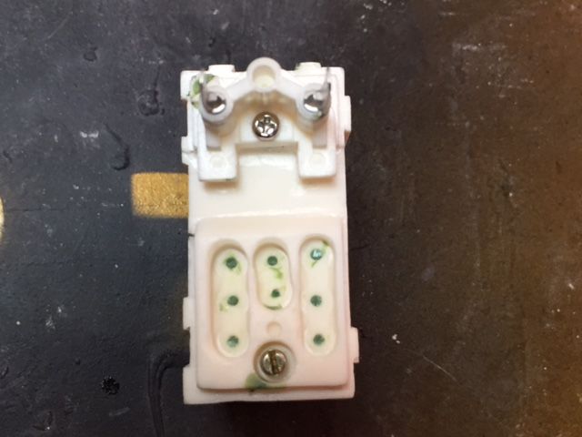
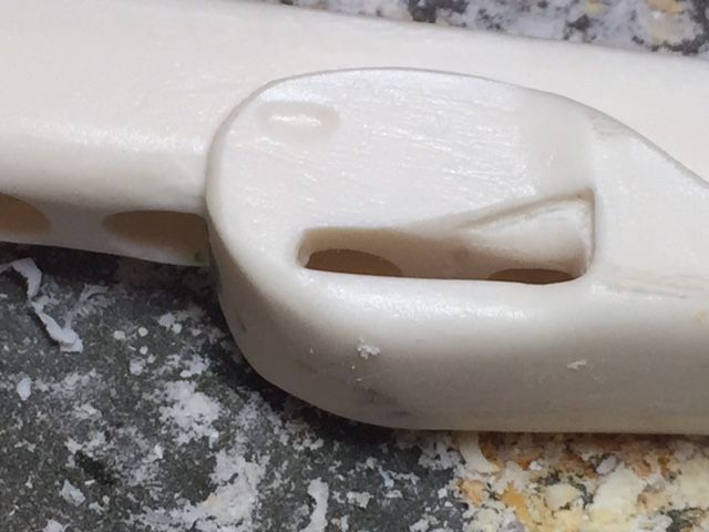
Further to Ian’s suggestion above and having reviewed the additional reference material referred to I decided to carry out a number of upgradesto my DD resin part to make it more accurate. So this is what I started with.
Firstly I marked out in pencil the area of resin that I needed to remove (using a small modelling file).
It isn’t until you start looking at the finer details that you realise how inaccurate this section of the kit is in particular the details to the front panel.
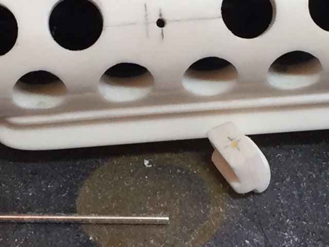
Therefore I decided to see what I could do to make it look more accurate. I measured the diameter of the cast resin concave recesses and then selected a wood drill bit of the same diameter (5mm). This was used to drill out a neat hole at each end of the 3 slots (Apologies for one of the photos as I seem to have had my finger obscuring part of the lens when I took it).
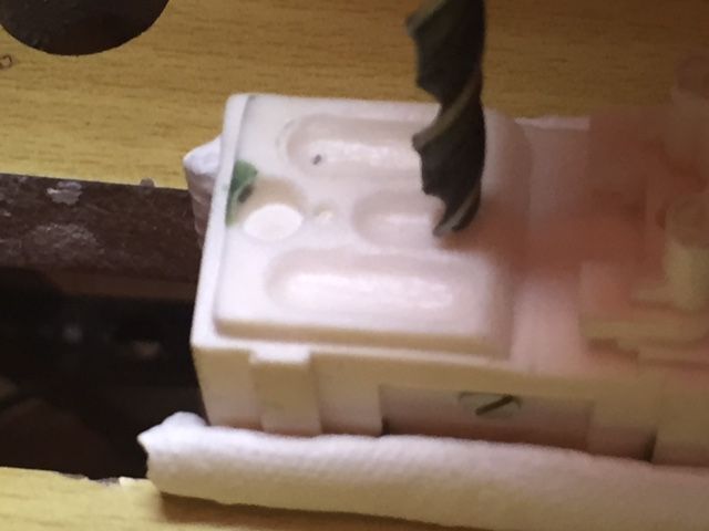
For the longer slots I drilled a further central hole and then used a mixture of a Dremel with a small sanding bit and files to smooth out the newly formed recesses. I also drilled holes for the two different sized circular concave recesses at the bottom of the front panel.
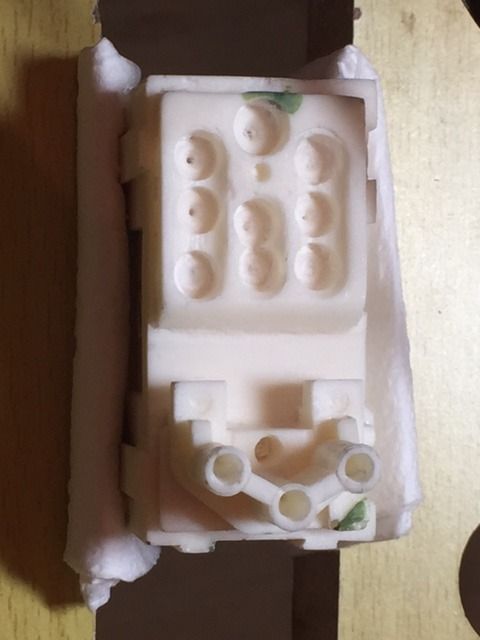
Once I had tidied up the new recesses I filled in the small guide holes formed by the wood drill bit with green stuff and installed the screws.
-
4
-
-
Another quick update.
I marked out the position of the centre of the bayonet lug and the fixing position on the receiver then drilled small holes in each about 5mm deep.
I then pinned them with a short section of the 2mm diameter steel rod from the counter shown on the first page of this thread.
-
Ian thanks for the info on the Hengstler I'll have a good look through this.
EDIT I have just looked at this and this is a great additional piece of detailing which I will definitely incorporate later today. Also looking at Blue Snaggletooth's page referred to there is some further detailing that I will try to tidy up.
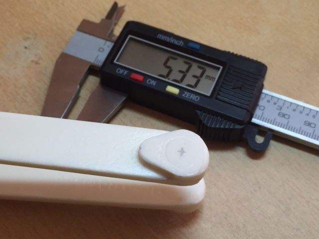
With regard to the screws I used to fix the rear of the scope rail with I have just measured them with some digital callipers and the dimensions are as follows:-
Screw head diameter = 5.8mm.
Thread diameter = 2.9mm.
Head thickness = 1.8mm.-
1
-
-
Next I moved on to adding some further details to the folding stock. I cut some short sections of hollow plastic tube, (3.7mm outer diameter), and glued these in to position at the fork intersection. These hollow plastic tubes sections were taken from the inside of a ball point pen.
Though this next modification isn't easily visible, unless you look for it, I decided to add something a little extra, I drilled out an additional 2 holes in the folding stock which can them be seen from the side of the stock.
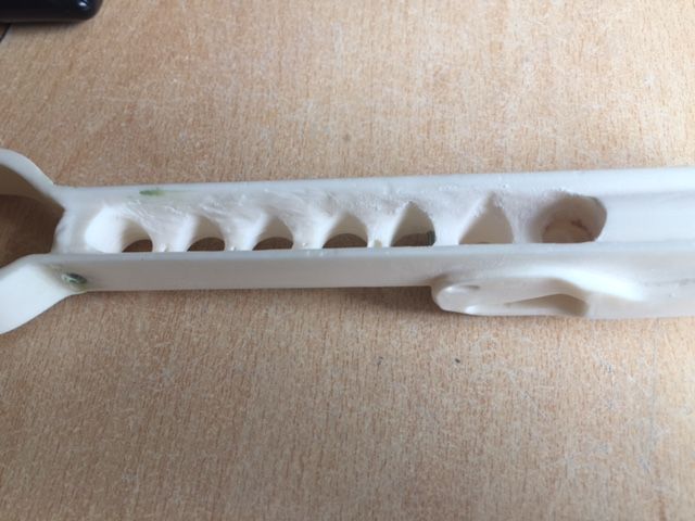
As I say this may be a little over the top but just gives me that little extra added realism and personally I think that it is worth it for the limited amount of additional work required.
-
2
-
-
Looking at mounting the scope rail on to the rear sight I decided that it would be better to fill in some on the details which would be hidden in order to provide more material for a stronger fitting for the screw (The screw is actually the screw provided in the wing toggles shown on the previous page of this thread cut to length).
Once the green stuff had fully hardened I placed the scope rail in to position and used the hole in the scope rail as a template to drill through in to the green stuff and resin below.
Once I have everything completed I will probably drop a little glue in to the hole and install the screw but for the moment I want everything to be easily removable.
-
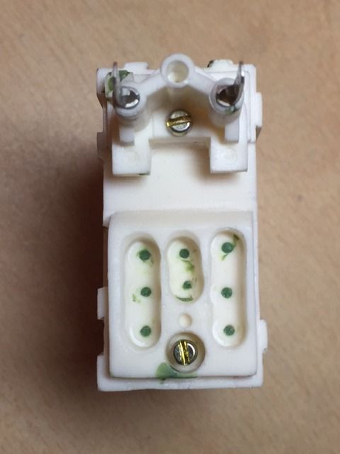
Well I decided on a small project after getting back from my break to ease myself back in to my build so decided to look at the counter assembly.
This is what I started with from my Doopydoos kit. As you can see the power connecters are little more than blobs of resin which needed to be filled off and the screw underneath them is very poorly cast and therefore also needed removing.
I started by drilling out the holes for the power connectors and screw using a 3mm diameter wood drill bit.
As I understand from my research the central detail between the two power connectors is drilled out but no power connector is located here. Can I just double check that this is correct with the master builders on here ?
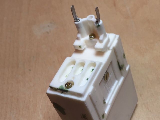
I then looked around for some small electrical connector, preferably with 2 small holes, and came across these in Maplin.
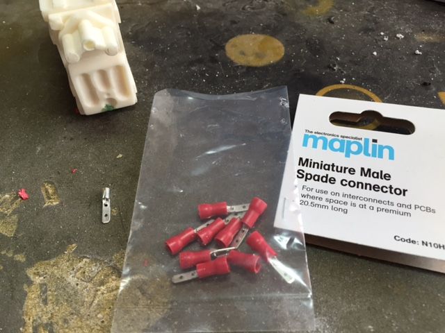
Once the plastic insulator is removed they are a perfect tight fit in the holes that I drilled.
As usual any comments, operations, suggestions or questions are very welcome.
-
2
-
-
Really amazing work Mike.
With all the upgrades and fantastic paint job that you have done you really can't distinguish it from a real gun.
As for the scope we have both worked on completely different solutions but this proves that on this type of upgrade, i.e. where there is no definitive screen used look, there is no one best method and I really like what you have done here.
Your build thread is very detailed with some really helpful photos and I am sure it will be a point of reference for many blaster builders to come.
If there is ever a thread simply listing links to some of the best build threads I think that this would be included. I actually think that this could be a good idea to help those starting there blaster research.
-
3
-
-
Ian/Aaron thank you very much for your detailed responses and very helpful photos which are a great help. I wanted to ensure that I order the correct colour of screw if I decide to include some very light weathering.
As I understand it iron, nickel and cobalt are the only metallic elements attracted to a magnet and as brass is an alloy formed from copper and zinc it isn't attracted.
I therefore assume the screws to be some form of steel i.e an iron alloy.
-
Hi Wayne and welcome to the world of blaster building.
First of all don't panic if you have a few problems you can use a product called green stuff which is a two part modelling putty to carry out repairs. It is easy to work with.
The best method I have come across for removing the parts from the resin is to place a sheet of fine sandpaper on a flat surface and then rub the parts on this gently. This gives you lots of control as long as you don't press on too hard and will give you s really smooth finish.
Lastly feel free to ask any questions that you have as there is a wealth of knowledge on this forum and we have all been at this somewhat frightening initial stage. You will soon find that what you fear now is nothing to be afraid of and will probably get to the stage where you are really enjoying the process of building your own blaster.
-
It's great to see that the servers are up and running again.
I also have quite a few pictures of what I have been able to do since getting back home which I will try to add tomorrow.
-
Ian could you tell me what diameter these original slotted screws are ?Feel free to check for my slot! These ones are original slotted ones. Direct from the M38 (well, M77C). Bit hard to get a great shot installed:
Also do you know if the screws are brass ?
-
The other option may be some plastic or metal pipe or even a suitbly sized pen or marker.
-
1
-
-
Hi Matt nice work on your build so far.
As for the broken pieces I wouldn't worry too much. Most issues can be solved with glue and/or green stuff.
The one thing that I did notice however is that the wooden dowl looks to have too large a diameter to match the resin cylinder.
I look forward to seeing how the rest of your build progresses.
-
2
-
-
Mike I think the 4mm-5mm diameter versions may be a little tricky to achieve though the 10mm-15mm diameter imperial logos sound much more achievable.
I'll give it a go when I am home and will probably try a variety of different diameters to see how small I can get them to print out well.
-
1
-

Thrawns Guard's ANH E11 blaster build
in Build Threads Requireing Maintenance
Posted
Tino - I should be able to recreate the sloping tilt switch.
The reason that it is currently sits horizontally is because the head of the screw touches the base of the channel. Once I find an alternative screw with a shallower head, which will allow the sloped position, I can push out the pivot pin, take the end cap clip apart and replace the screw.
It will be an easy fix but finding the correct screw may take some time unless I get lucky.