

Thrawn's guard
-
Posts
479 -
Joined
-
Last visited
-
Days Won
9
Content Type
Profiles
Forums
Gallery
Articles
Media Demo
Posts posted by Thrawn's guard
-
-
Thanks for letting me know Scott.
I have decided to try my hand at making some power cylinders. After all the worst case scenario is that if they are not up to standard I can still go and buy some anyway.
I have quite a bit of research to do to decide upon exactly how I am going to do these and then collect the parts but that is half the fun of it anyway.
-
@ Brian - Thanks for getting back to me I'll have a look at these.
@ Aaron - I'll take a look at the PM. Thanks very much for your help.
Hopefully at the end of it I will be able to purchase or reproduce some decent power cylinders.

-
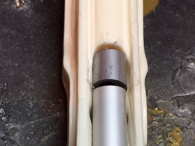
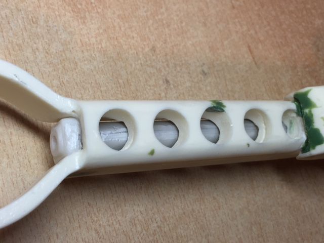
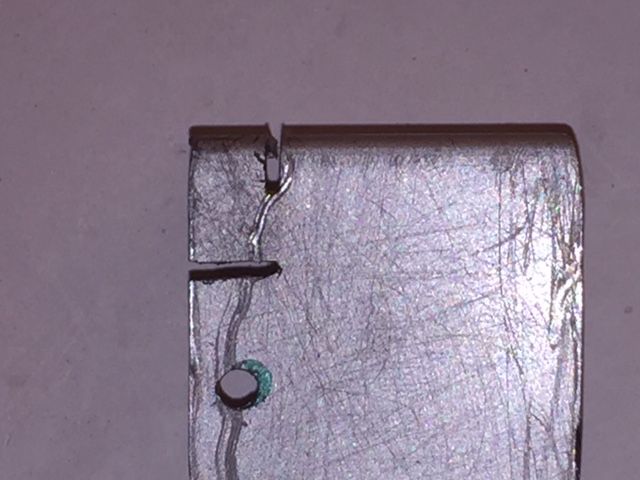
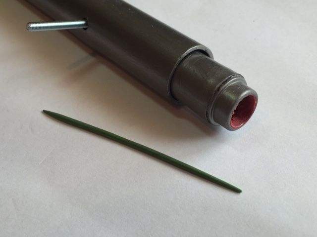
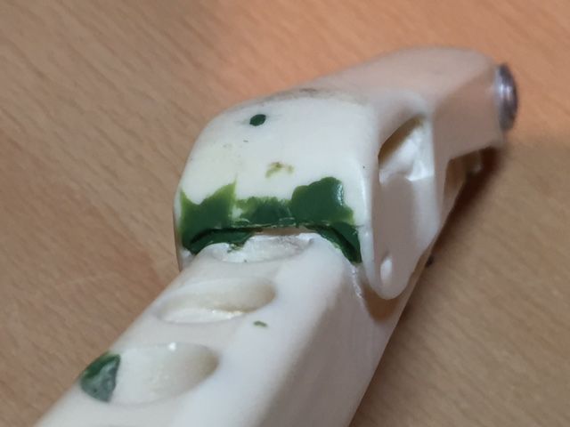
Looking at the joint between the end of the aluminium tube and the cast resin cylinder there was a gap approximately 20mm long which needed to be filled in.
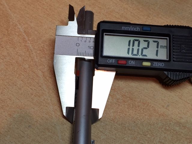
I decided to look for something to fill in this gap with as close a match as possible (This turned out to be a metal effect plastic ball point pen). I double checked the diameter of the pen compared to the diameter of the cast resin cylinder using a digital calliper.
I then cut out a section of the pen approximately 16mm long using a cutting disk on a rotary drill and placed it in to position.
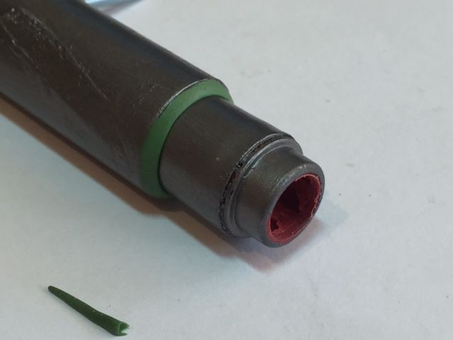
Using some green stuff I filled in the gaps at both ends of the infill.
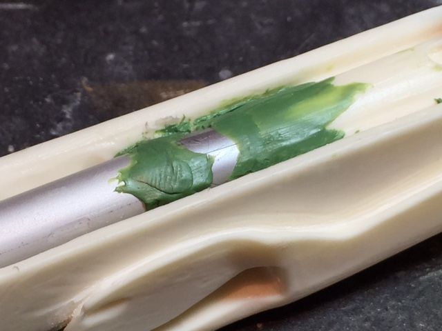
Once the green stuff has fully hardened I will carefully sand it down flush with the rest of the cylinder. I will post a picture of this once finished.
-
Thanks Ian that will be a great help and will be much appreciated.
In the meantime I'll keep looking but I haven't come across any exact dims on Andy's threads as yet. To have a full set of accurate dimensions dimensions would be great but I don't believe that I have seen them in the past.
So far I've been looking at trying to scale one dimension from another.
-
Hi Guys.
I am probably going to have a go at making my own power cylinders and have a couple of questions to get me under-way which I would be most grateful if anyone can answer.
1) Are the front and rear caps on the cylinders exactly the same size ?
2) The correct diameter of the cylinders appear to be in the region of about 10mm. Is this the case ?
-
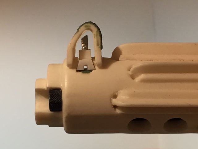
Another quick update.
I glued the front sight guard in to position.
-
 2
2
-
-
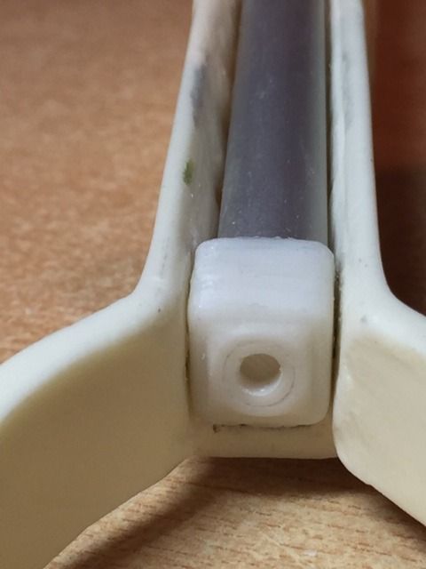
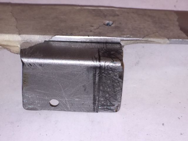
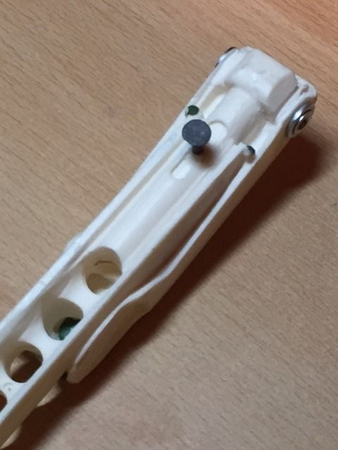
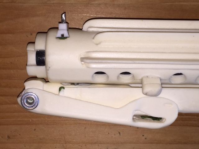
The final detail required to the folding stock is to fit the square bracket detail and the connecting tube. I used the aluminium tube provided in Tino’s completion kit however a suitably sized, (10mm diameter), pen could alternatively be used to provide a similar effect.
Firstly I set about removing the resin cast ‘square‘ bracket detail using a rotary drill (Cutting disk, engraving bit and sanding bits).
As I cut away the resin cast bracket I checked on a regular basis to see how the replacement square bracket was fitting.
Once I had managed to remove all the resin cast bracket I tidied up the channel cut in to the folding stock with a fine nail file.
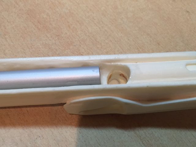
Finally the square bracket and aluminium tube were glued in to position using some E6000 glue that arrived today (So far it seems very good glue).
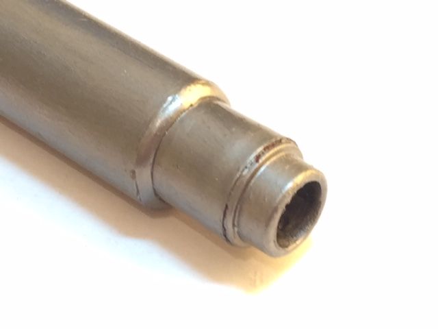
Tomorrow I will need to fill in the small gap between the end of the aluminium tube and the cast cylinder tube.
-
2
-
-
Chris, its simply fun to watch you building that thing

Noticed just one thing: your resin part is parallel to the aluminum part, while the real thing is higher on the side with the pattern and lower on the T-side. Is that something you can still recreate?
I have been re-looking at this end cap catch.
The reason that the 'level' was not sloped was that the small screw fixing used to secure the thing spring clashed with the base of the channel.
I have since removed the screw fixing but am struggling to glue the metal spring to the resin as the glued bond keeps breaking when the clip lever is pushed.
I have tried superglue and araldite so far without success but have seen reference to E6000 glue (I have ordered a tube). Hopefully this glue will be much stronger.
-
I'm glad that you like the details to the front sight and folding stock Brian.
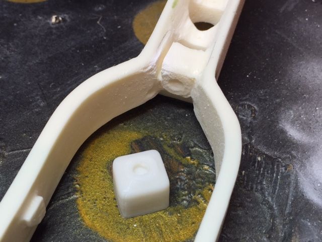
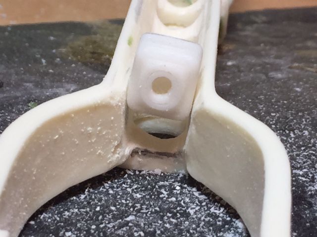
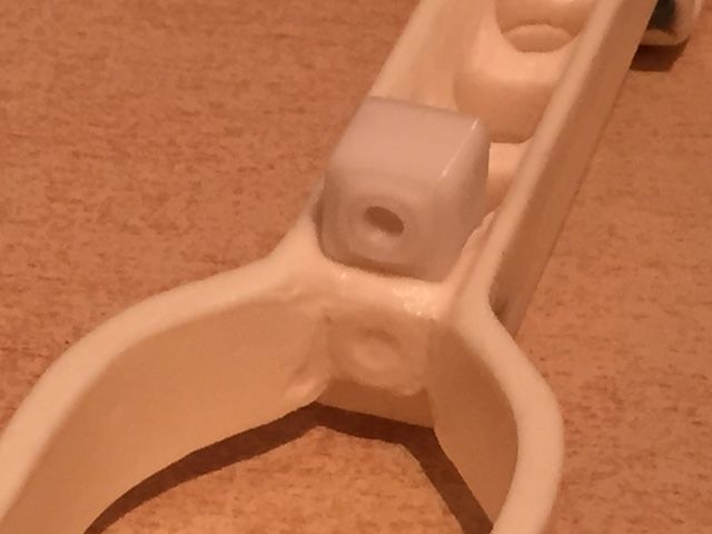
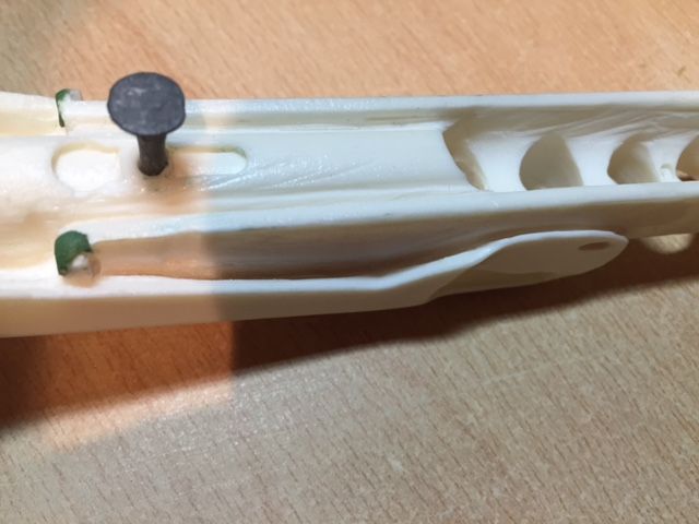
I also looked at tidying up the joint at the fork in the folding stock.
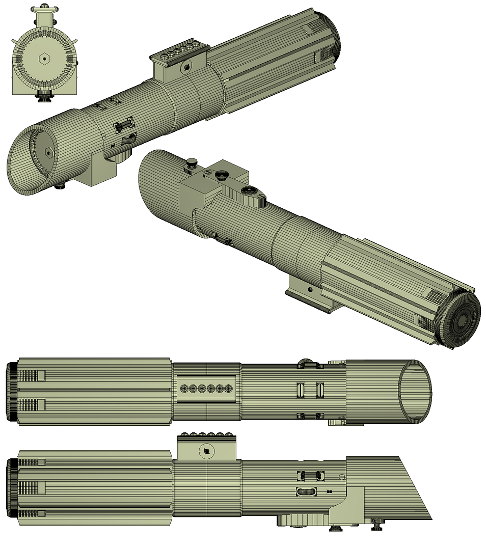
Below is a photograph of the detail in question that I have been working on and 3D printed earlier this morning, (placed on top of the resin cast detail for comparison) which I intend to install tonight.
-
1
-
-
Aaron - As usual your work on this is second to none. Very impressive indeed and thanks for sharing.
-
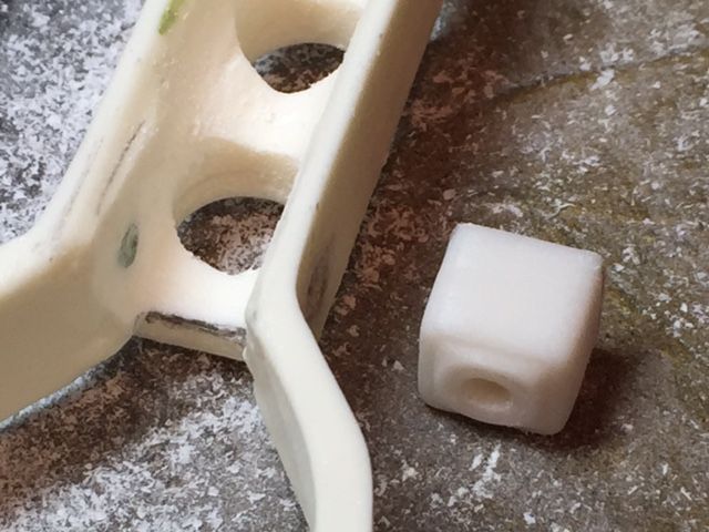
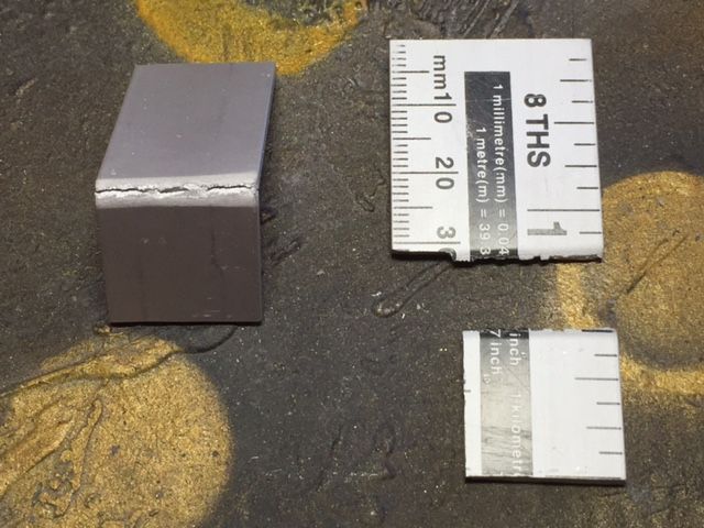
Bill these are the final dimensions I worked to.
The overall length = 11mm.
Width = 5mm.
Depth = 5mm.
-
I've also been looking at maybe a Vader lightsaber hilt but the prices for something decent are a bit higher than I wanted to pay.
It's funny you should say this as I have been working in the background on maybe making a ESB Vader lightsaber.
Perhaps this will be my next project though I really should start looking at getting some armour.
-
1
-
-
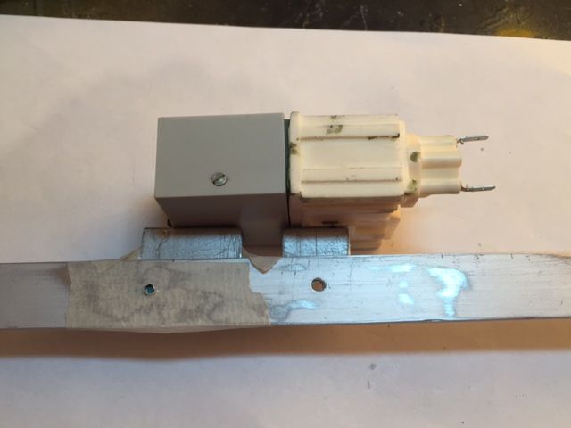
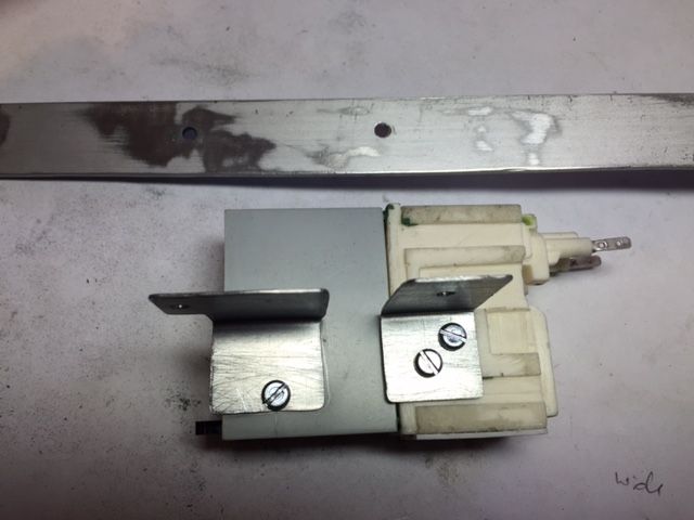
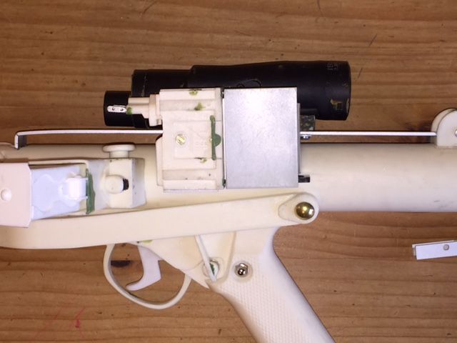
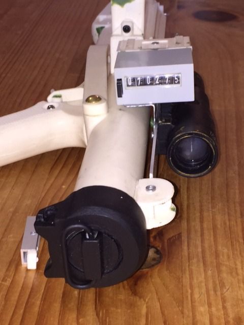
Attaching the counter and scope to the scope rail turned out to take much longer than I had expected.
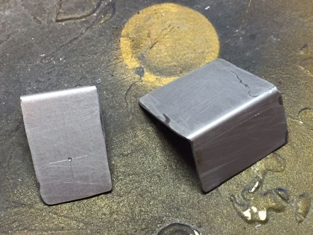
I started out making separate brackets to connect the front and rear sections of the scope to the rail however found that the brackets kept snapping when I got close to a 90 degree angle.
After several attempts and much time wasted I decided to have a look around to see if I could find something else to form the brackets.
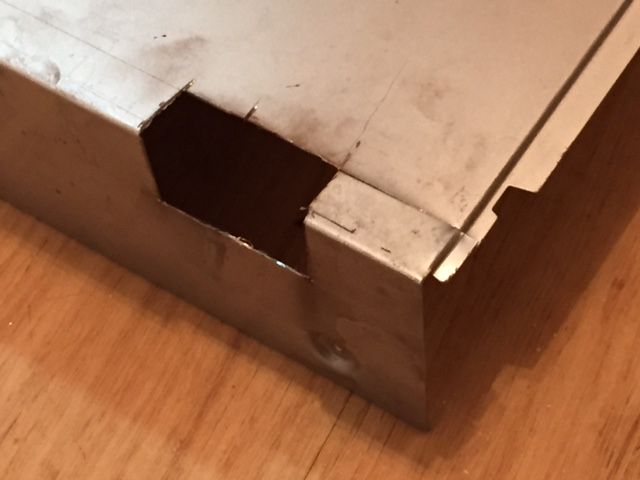
I came across an old DVD recorder in the garage that is waiting to go to the tip. Looking at the case I found that it was a thin but stiff steel so set my mind on cutting suitable sections from the case which already had the 90 degree angle that I needed.
Taking my Dremel I carefully cut out the basic outline of the steel that i would make my bracket with.
I then carefully marked out the position of the counter in relation to the receiver. To ensure that i got the correct positions for the fixing hole i taped the brackets to the scope rail using some making tape. This allowed me to play around with the positioning until i was happy.
Once I had the positions decided I screwed one of the brackets in to the rear resin section of the counter.
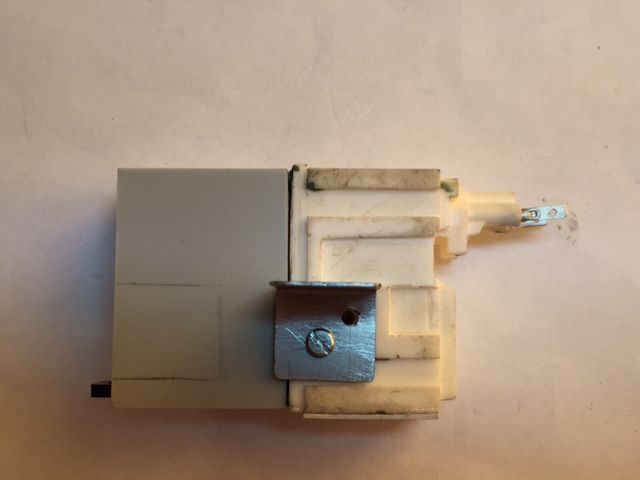
The again before I did too much more work I treble checked the position of the counter when mounted on the rail by comparing it with the blueprints in the FISD reference thread.
I could then use the brackets as templates to mark out positions of holes that needed drilling.
I also checked what part of the mounting bracket fixed to the real counter section could be seen from the side and marked this area out to be remove.
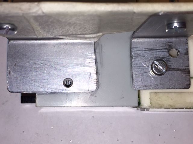
Unfortunately with 8mm of steel to cut and 3 screws to shorten my Dremel has died (I hope that it is still under guarantee). therefore I had to resource to a handsaw to complete the last cut to remove the notch from the second mounting bracket.
Anyway finally I had the two brackets which once connected to the scope rail will prevent to two sections of the counter from accidentally coming apart whilst also letting me remove them and change the numbers at a later date if I so wish.
-
Another quick modification.
Looking at the end of the inner bolt there were two issues that I wanted to improve (I know that it would eb hardly noticeable but I thought that timewise it wouldn’t take very long so why not sort it out). Firstly the end of the bolt shouldn't be solid and secondly the inner section used to form the bolt was slightly smaller than the inside diameter of the outer section of the bolt. Therefore I wanted to seal this up so that it looked like one single part.
This is what I started with.
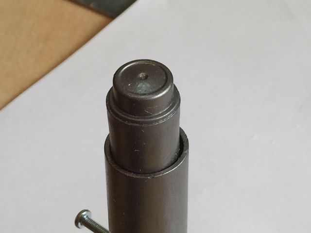
I then drilled out the end of the inner section off the bolt.
Once I had drilled out the end I rolled out a thin roll of green stuff which I then used to seal the gap between the 2 sections.
When the green stuff had fully cured I applied some gun metal paint (I may add some additional colouring to represent grease at a later date).
-
3
-
-
As mentioned previously since the charging handle is cast directly from a real handle and the wall thickness of the resin Doopydoos kit is much thicker than the wall of a real sterling the charging handle, if fixed directly to the inner bolt, is too short. Therefore I looked at ways of making a suitable modification.
This is what i started with.
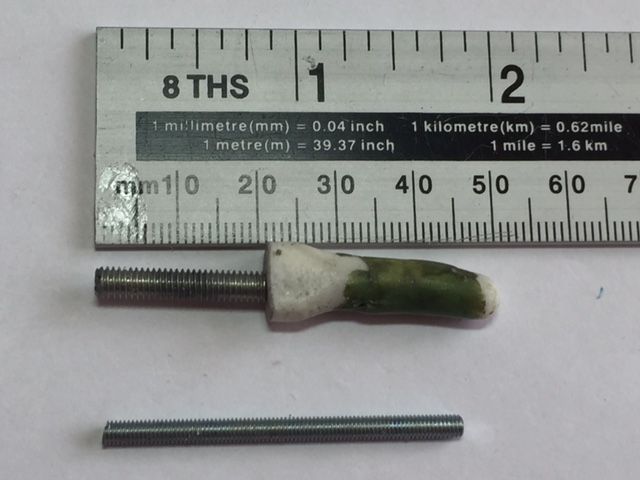
As I had noticed this Issue until after I had glued the resin handle in to the threaded rod any modification needed to be carried out on the tip of the handle. I decided however that the handle would need reinforcing to provide additional robustness so carefully drilled a hole in the tip of the handle so that I could insert a new section of threaded rod (cut from a mechanical screw).
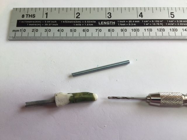
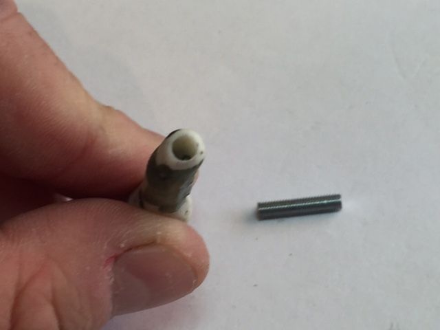
The aim was to increase the length of the tip of the handle by 8mm so that the handle projects out of the receiver by the correct distance.
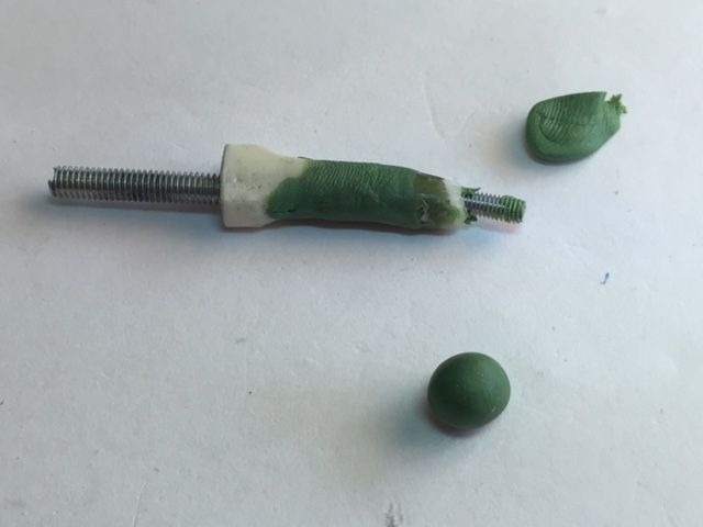
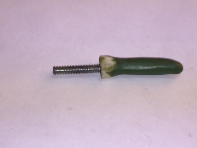
The threaded rod was then glued in to the hole in the end of the handle and green stuff was applied and shaped over the top.
This is the finished product.
-
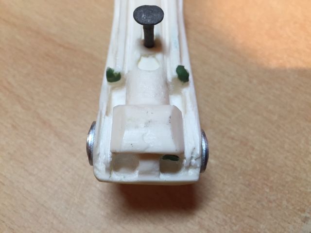
Further to my post yesterday here are a few updates of what I managed to work on over the weekend. As usual if anyone has any comments or suggestions they are most welcome.
Using a mixture of a Dremel and some clay moulding tools I have cleaned out some of the excess resin in the folding stock to bring out the details.
-
Thanks for your kind words and coming from you this means something.
I totally agree Mike much of what I have done is also copied from or inspired by other build threads that I have read. In fact I think that this is what makes FISD so great. We all share what we have done and everybody gains. You can see from the builds the constant improvement and innovation.
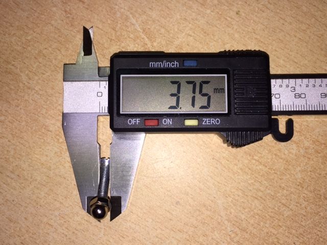
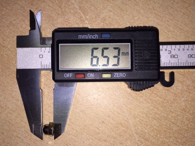
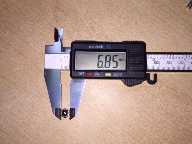
Anyway back to topic. I have taken some photos of the dome head bolt complete with measurements (Conversions to inches provided below).
3.75mm = 0.148inch
6.53mm = 0.257inch
6.85mm = 0.270inch
Diameter of the outer thread.
Overall depth of the nut
Distance ancross the flats.
If you need any more information let me know.
-
Wow what a fantastic build.<br><br>
This is the same armour I intend to buy and do a self build on so I will most likely refer to this on a regular basis.<br><br>
It does seem a little daunting though.
-
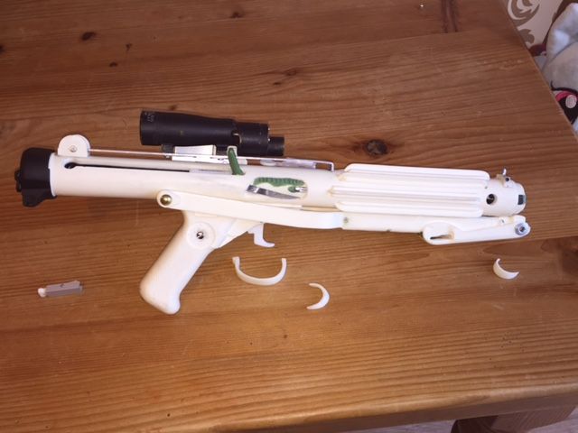
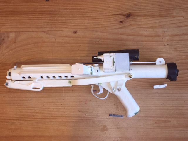
My build is now 95% complete as I have had quite a lot of time available this weekend to get my teeth in to the build (I will post some updates during the course of this week).
I still have the power cylinders to add, clearing strip to add to the rear bolt, trigger guard to attach, end cap clip to amend slightly and attach, trigger to reinstall, along with the flash guards and front sight guard to glue on but I think other than that I am about there.
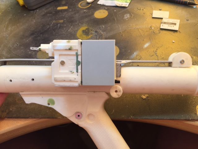
Therefore I thought that it would be a good idea just to double check everything was fitting OK before I start the painting process. Anyway without further ado here are a few quick pictures of my test fitting.
I don't know what I'll do with my time once I finish this build.
-
2
-
-
Thanks Tino it's good to get some feedback from Dan and yourself as you have both got great builds and have already gone through the process of painting.
I also had a reread through your thread earlier and had forgotten how much detail you provide with regard to the paint that you applied.
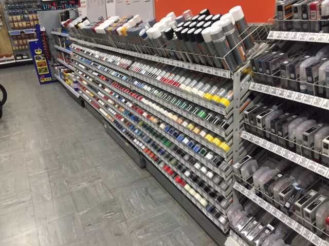
Well I had a quick drive to my local Halfords store today to see what they had and was very pleasantly surprised with the amount of paint that they have in stock................just about anything you would ever want (including glow in the dark paint though I wont be using that in this build
 ).
).
-
1
-
-
If we ever have a list of recommended blaster build threads I think that this should be included on the list.
-
1
-
-
I just came across this build and will be reading through it on detail later however from what I have seen so far it is another great build.
-
Thanks for the advice relating to the Chaos black paint on resin. I had used it previously on metal and plastics and it worked fine but never on resin.<br><br>
I have both a Halfords and a B&Q not too far away so will most likely call in today to pick up the paints you mention above.<br><br>
One quick question. Does the Halfords gloss lacquer not make the main body of the blaster too glossy ?
-
Your work on the counter really makes a big difference Mike.
I look forward to seeing your finished version.
Great work.
-
1
-
Thrawns Guard's ANH E11 blaster build
in Build Threads Requireing Maintenance
Posted
Anyway now on to the exciting bit.......painting.
At first it seemed a little daunting however when I thought about it there is nothing to worry about...............If I make a mistake I can simply repaint over it.
I will post some update picture over the weekend to show you all how I get on.