

Thrawn's guard
-
Posts
479 -
Joined
-
Last visited
-
Days Won
9
Content Type
Profiles
Forums
Gallery
Articles
Media Demo
Posts posted by Thrawn's guard
-
-
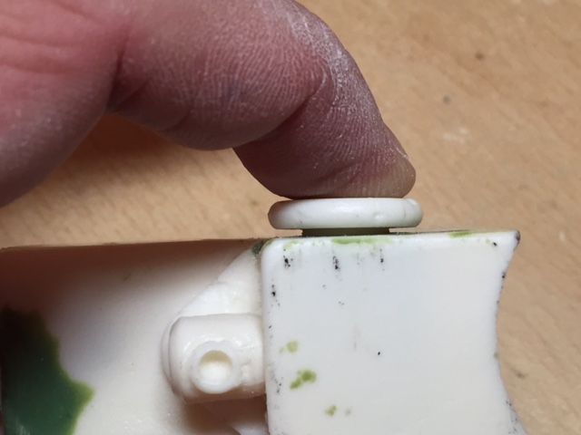
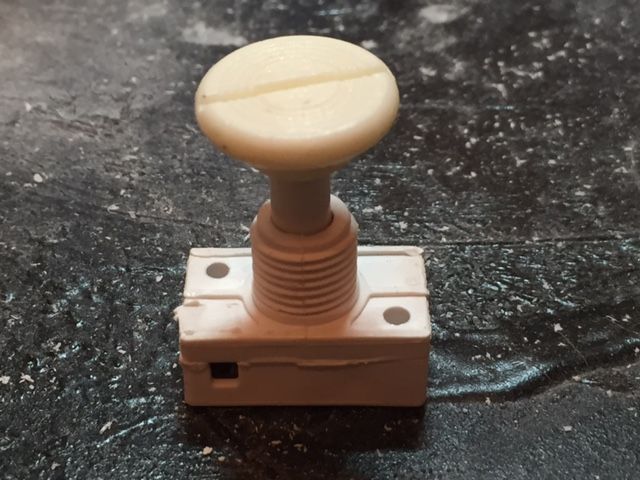
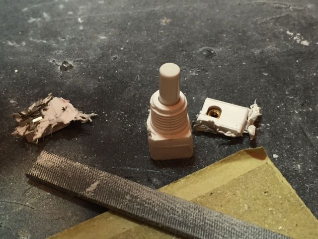
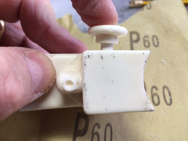
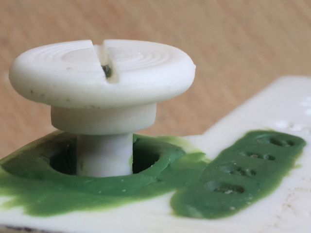
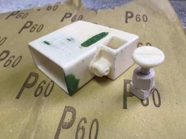
Taking onboard the comments and advice about the magazine release button I decided to see what I could do with the push switch currently installed as the new push switches are not due to be delivered for a few days.
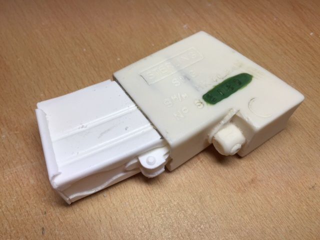
I removed the resin switch and cut down the stalk of the push switch using a cutting wheel on the Dremel before tidying everything up with fine file. I also took the opportunity to hollow out the magazine housing a little more to allow the upgraded magazine to be fully inserted.
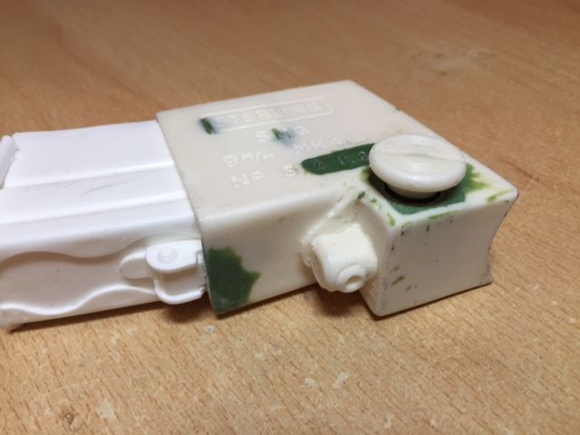
The next task was to check that the button was now located at the correct height and after some further minor filing I was happy that I had the button located at the correctly.
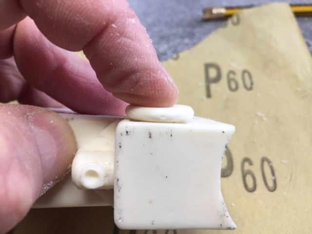
I carefully test fit the button before applying a small amount of super glue to the base of the resin button and top of the push switch. Once the two sections of the switch were glued I double checked that the button was correctly centred and that it would fit in to the tolerance hole when pushed.
-
 1
1
-
-
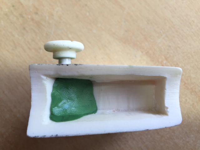
Hmm after thinking about it a little more I think I was missing the point about altering the length of the stem.
If I shorten the stem I could get the button to the correct height and it would have a solid spring action I just wouldn't get the switching click sound (I was getting fixated on the switching sound).
I'll give it some more thought after all the new switches that I ordered were less than £2 for 5 delivered so there are no issues there.-
1
-
-
Tim/Tino/Michael – Thanks for the feedback which is always welcome.
Unfortunately the switch mechanism requires quite a bit of vertical movement and I don’t really have the space to drop it down any further. In any event if I did drop it down further the switch would actually start to disappear within the top of the magazine housing.
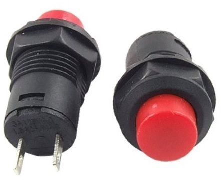
I do however like the basis and feel of this modification therefore see that the best solution will be to find an alternative push switch with a much reduced vertical travel. I guess that I need a switch that has a vertical travel equal to the depth of the recess under the circular resin button.
I will search around and see what I can find.
NOTE - I think that I may have found something suitable on Amazon

Order placed so once it arrives I will have a go at reworking the magazine release button modification.
-
1
-
-
Wow.........as soon as I start to think there is not much else that can be thought of to upgrade a particular item I read a post such as this.
I guess this is what happens when you have a group of interested people constantly thinking what else can I do to improve/innovate the build.
Great work and an amazing attention to detail.
-
2
-
-
Hi Michael I also like the sound it makes and it also feels 'correct'.
Unfortunately the height is the function of the particular push switch that I had but I'm sure that there are others available with less travel.
I may have a look on the internet to see what I can find.
Do you think that the height is a big issue with regard to getting the blaster signed off for Centurion use ?
-
Richard you are off to a great start.
Hats off to you for jumping in at the deep end and modifying the scope as the first part of your build.
I have been putting my scope off and started working on much simpler parts of the build to get used to the material and the tools (I have not worked with resin previously).
As you say above where you have holes in the sides of the scope this can easily be fixed with green stuff so it is not something to worry about.
I look forward to seeing how your blaster progresses,
-
1
-
-
Post the video to YouTube, then copy the link to it and paste it into your post it here on the forum and it'll automatically turn it into and embedded video. That's how I did the video clip of the rear lock in my own blaster build thread.
Dan
Thanks Dan.
This is a video showing the magazine release button in operation.
I think that this effect would work great with a trigger.
-
1
-
-
Can anyone tell me how I can post a short video ?
It's only a few seconds long but shows how the switch works.
-
You will need to go a little deeper to make sure the little lip at the front of the magazine is snug against the magazine well. looks like about an 1/8" more in front and 3/8" in the rear. The magazine catch also needs to be seat further.
 d
dGood spot Michael and thanks for the feedback. Looks like I know what I will be doing after work tomorrow.
I don't know if after this build I will ever get rid of all of the resin powder
-
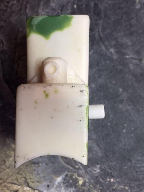
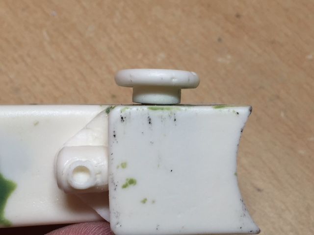
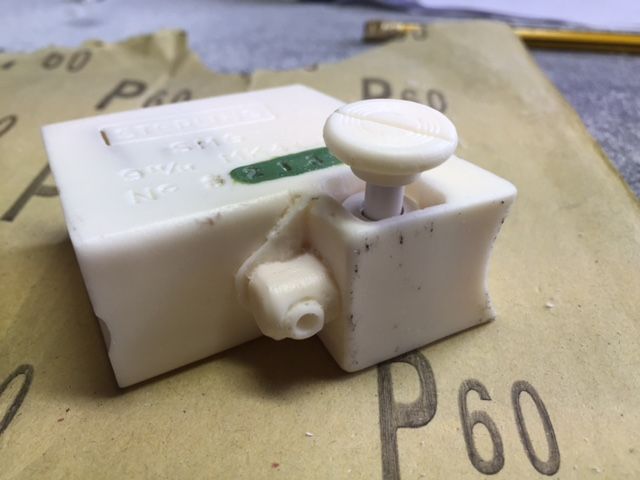
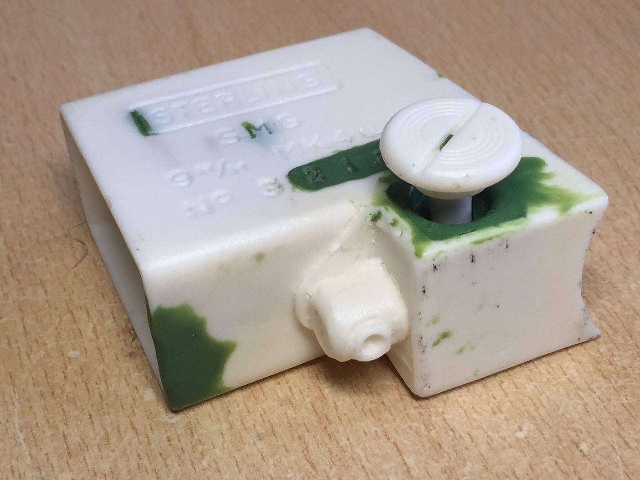
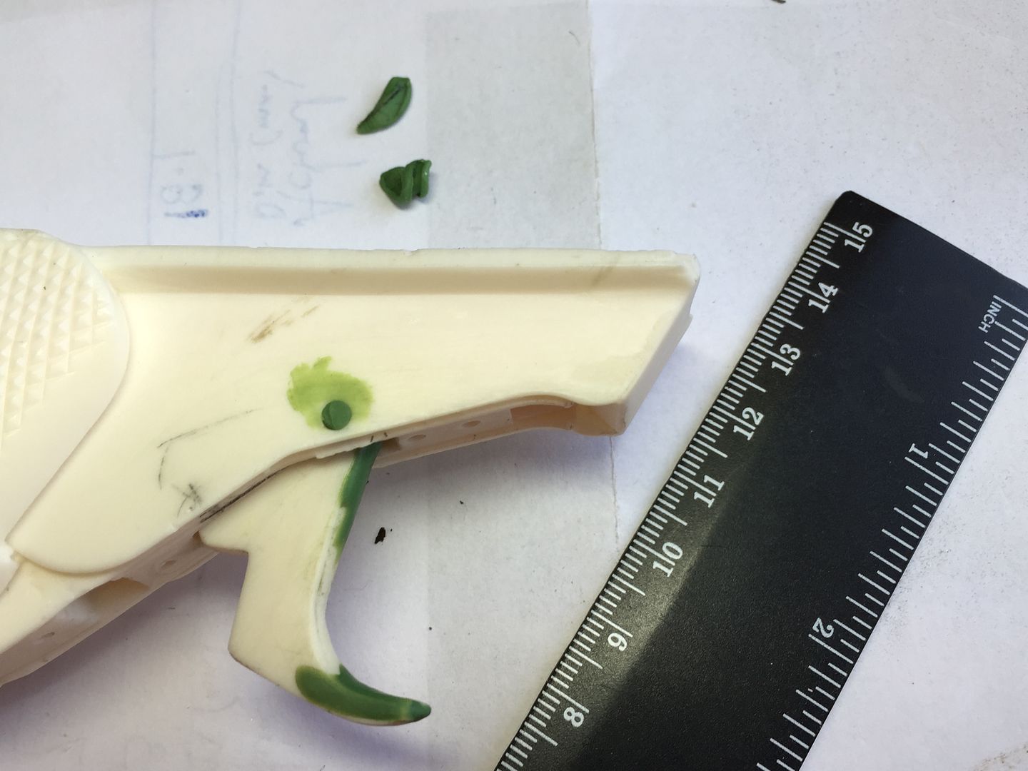
As mentioned yesterday I have been working on something a little different for the magazine release button.
I wanted it to actually move rather than simply glue it in place and have seen a compression spring used to give this push button effect. What I thought however would be interesting to investigate was to actually fit a compression switch within the magazine housing to give a real mechanical feel to the button when operated.
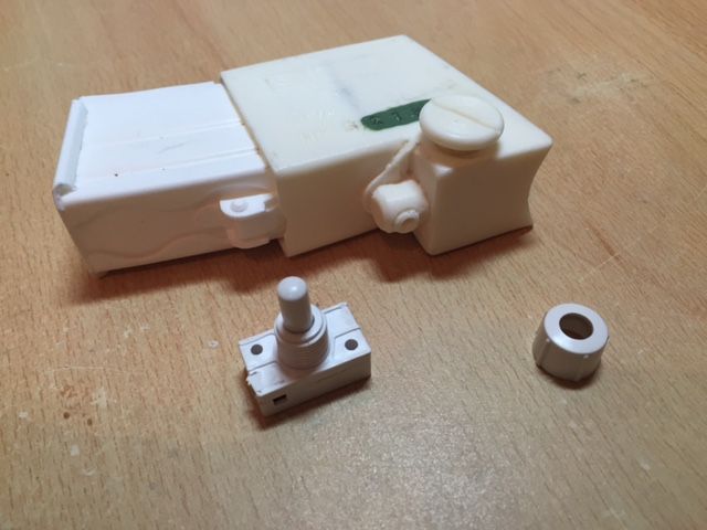
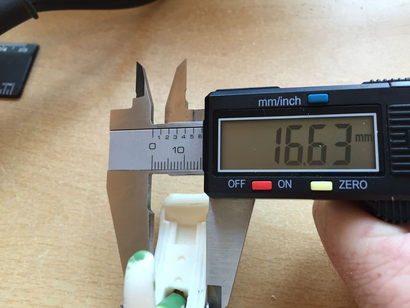
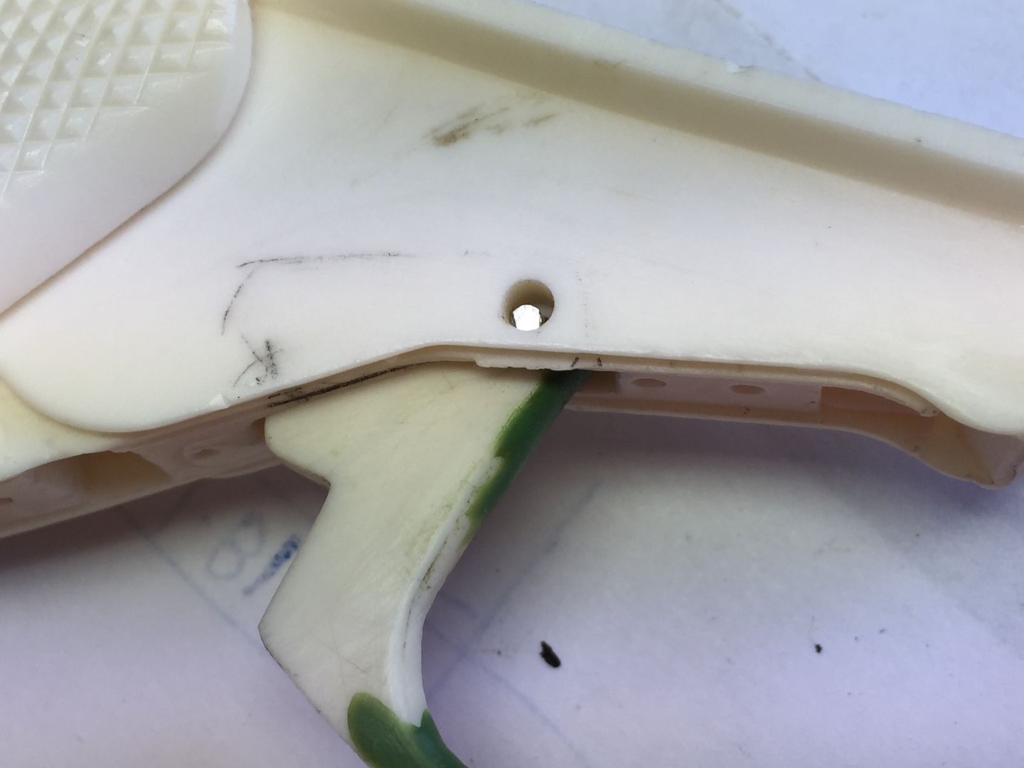
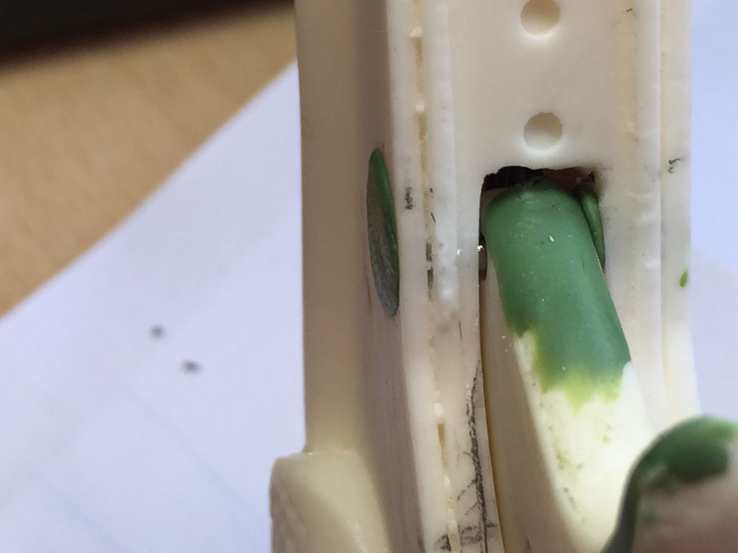
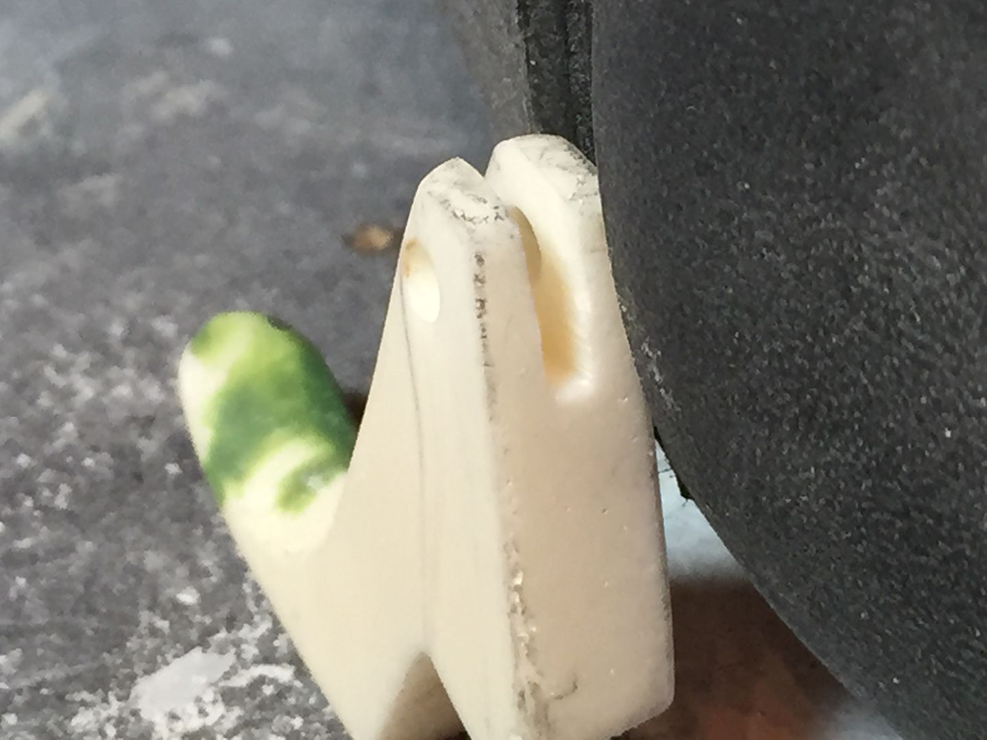
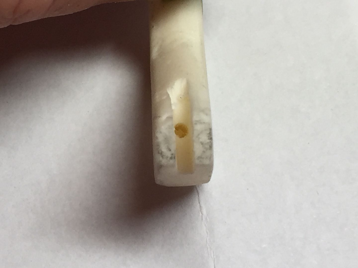
With this in mind the first task was to check the diameter of the switch with a digital calliper before drilling a hole in the underside of the resin release switch, (5mm diameter), so that it would slot tightly in to the top of the push pull switch.
Once this had been done I used a Dremel cutting wheel to remove the ends of the switch (I only needed the switch mechanism and the electrical connections would make the switch too large).
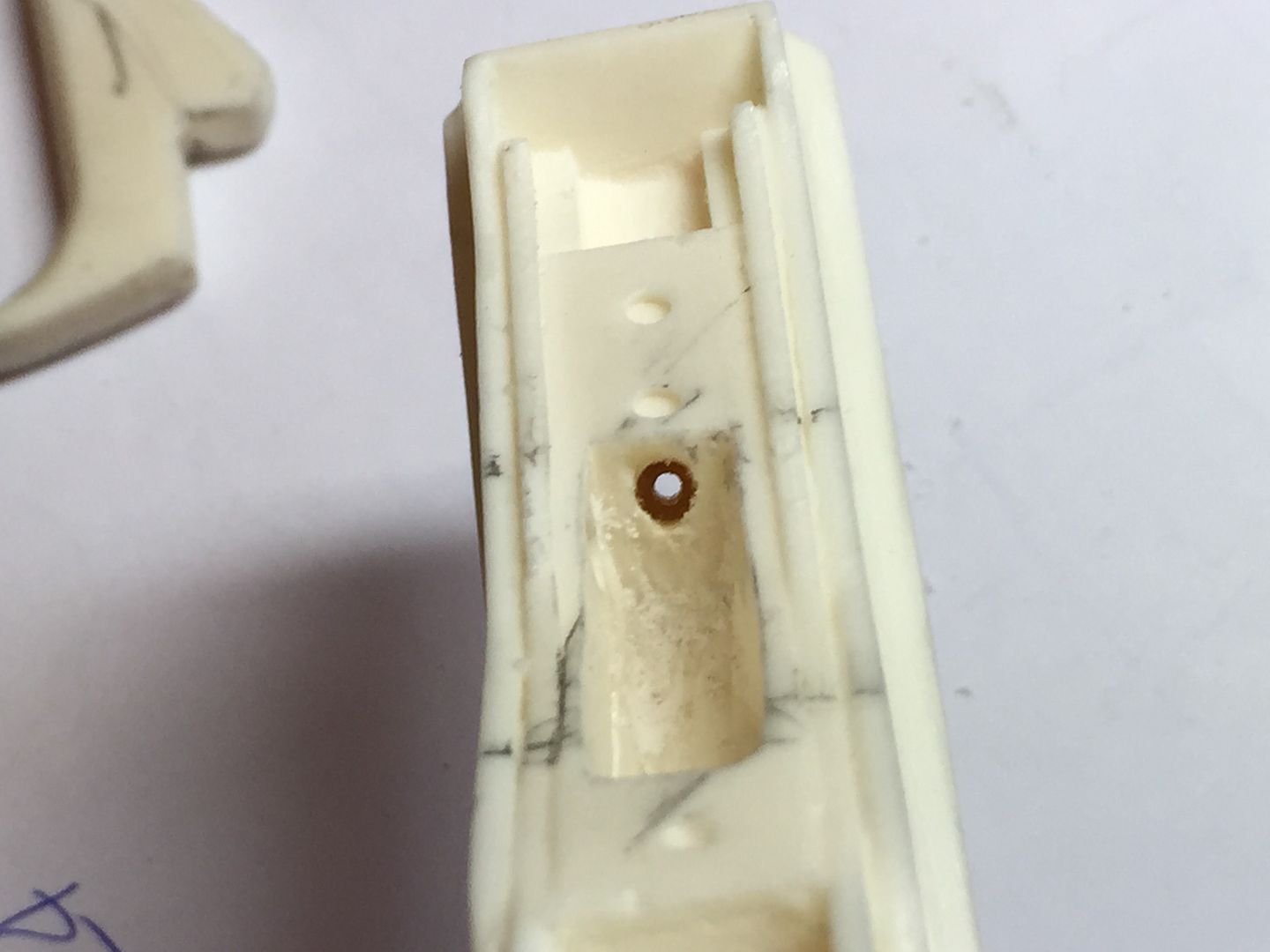
I placed the cut down switch on top of the magazine housing and used a sharp pencil to mark out the position of the switch so that I can see where I would need to hollow out the resin.
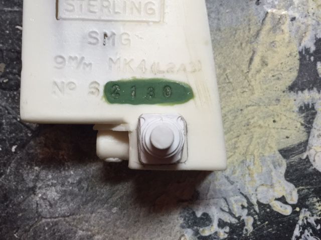
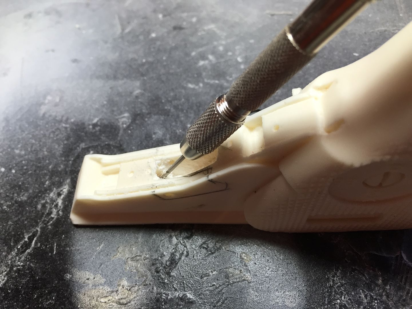
The hollowing out of the magazine housing with the Dremel took some time to open up to the correct size and depth but once done the switch was dropped in to place. I then double checked that the positioning and depth were correct and once happy that was the case I glued the switch in to position with super glue.
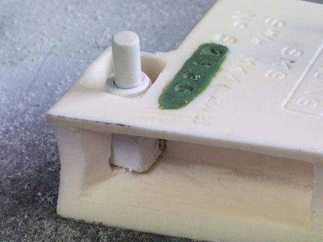
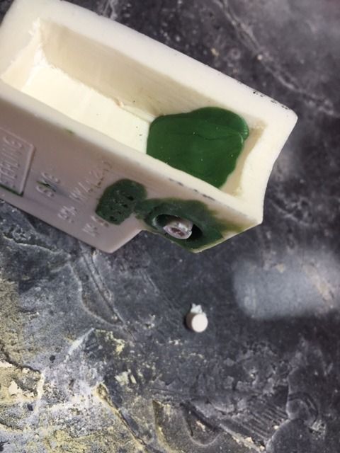
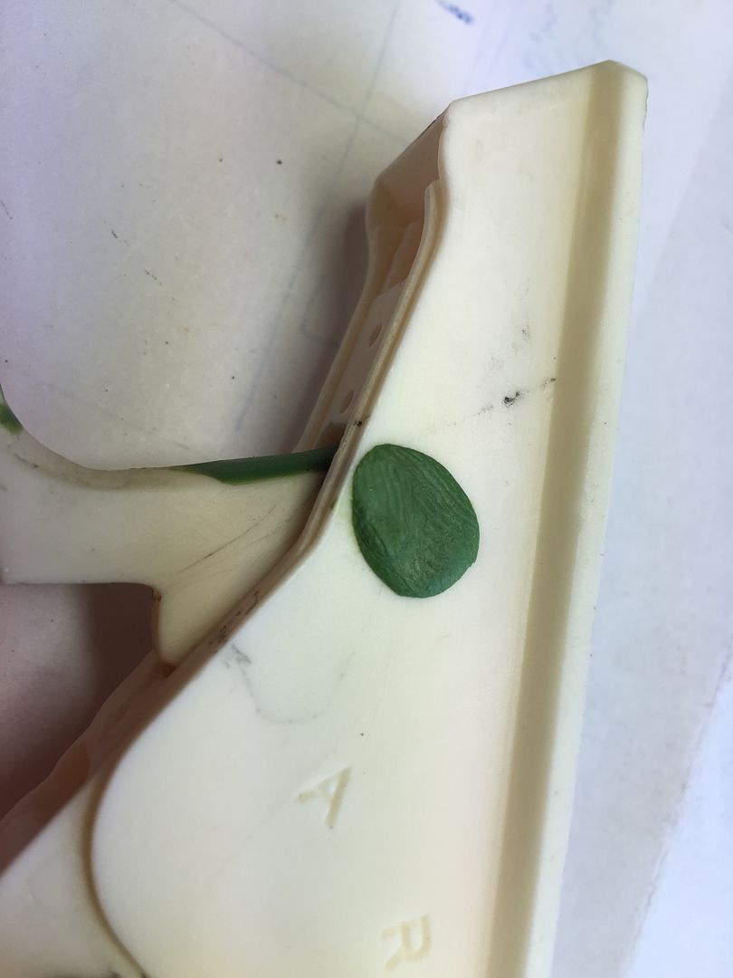
In order to provide a neat detail I wanted to hide the square profile of the cut that I made in order to drop the switch in to position. Green stuff was then moulded with the use of a clay sculpting tool, (and fingers), in to the corners of the square opening and gently sculpted in to position. The switch was operated throughout this stage to ensure that no green stuff, once hardened, would prevent the switch from working.
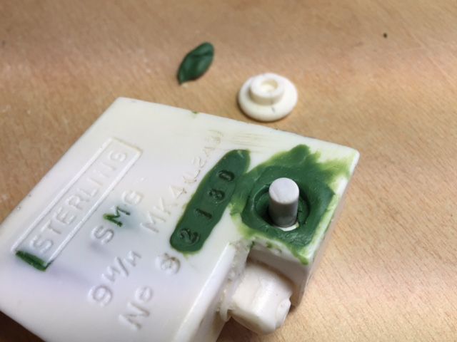
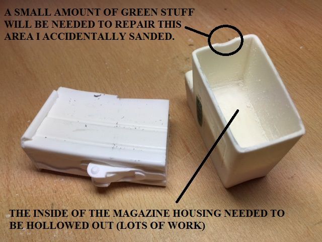
As usual I had some green stuff left over so I took the opportunity to repair the edge of the magazine slot that I had previously sanded down occidentally (This will be filed/sanded as required once dried to ensure it is perfectly blended in with the resin).
The remaining green stuff was used to provide additional restraint to the switch.
After all this work this is the result (I will file and sand it tomorrow when the green stuff has fully hardened.
-
Scott hopefully both will last but at least we have some alternative methods for people to consider.
I also thought about replacing the compression spring in the trigger mechanism with a push switch, (similar to the switch in my next post), but only have the single blaster build so had to make a decision which of the two methods to use.
Maybe someone carrying out a future build will give this a go.
-
Hi Brian I have only recently come across this thread, (and haven't as yet finished reading all of it), but have literally been inspired by your attention to detail and some great innovative ideas...... I hope that I can incorporate some of it in to my build.
What constantly amazes me on this forum is the skill people have and there willingness to share what they have done to help others.
Blaster builds continue to evolve and this can only be good for all of us.
-
2
-
-
I'm very interested in how this works out Michael. So far it looks very impressive.
-
On a positive note my 8x20 Monoculars that I intend to use to upgrade my scope arrived today.
I also have TJay's great looking completion set on the way and also managed to get one of his 6 digit working counters ordered so I will be kept busy on the build for some time yet
I had originally intended to strip down a cheap counter that I ordered from Amazon, (See page one of this thread), to use some of the parts to convert the resin counter supplied in the Doopydoos kit however I couldn't resist the temptation to add that extra bit of realism.
Next on the list of things to do is a working magazine release button for which I have something a little different in mind. I will post details and photos soon (Hopefully it will be a success).
-
1
-
-
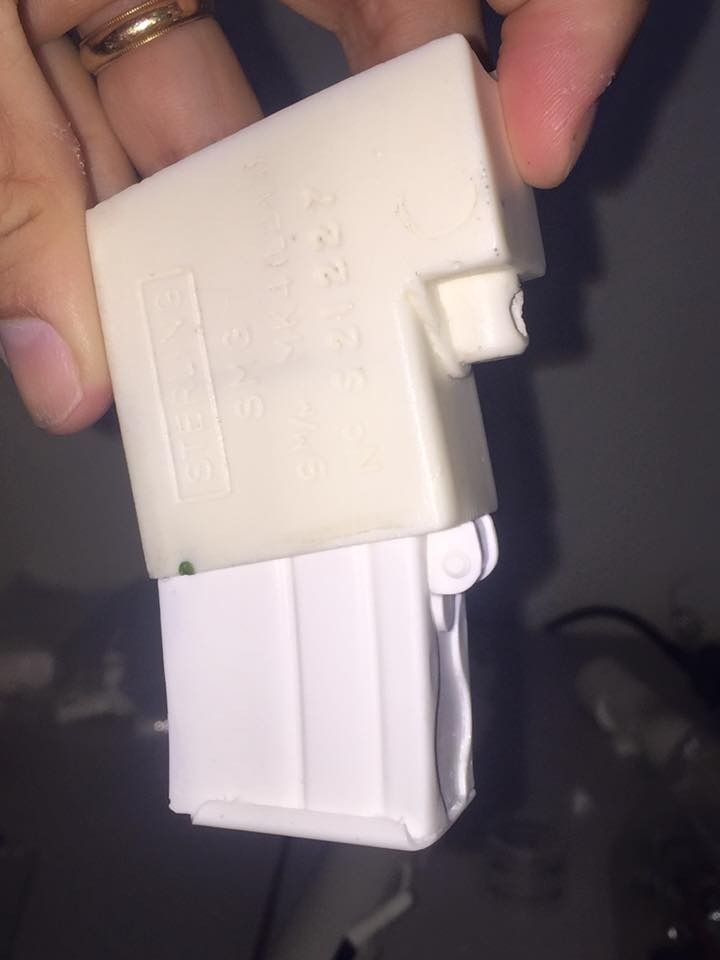
Further to my post yesterday evening I have not had chance to work on the blaster build today as we have had visitors. However here are some photos taken of my work on the magazine upgrade promised yesterday.
As you can see from the first picture Gazzmosis' magazine is far superior to the one provided in the Doopydoos kit and in my mind is well worth the upgrade.
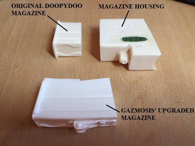
I intend to be able to remove the magazine therefore want to keep the entire magazine intact however if the magazine wasn't to be removed shortening the magazine would be a much easier and quicker task than hollowing out the magazine housing so that the magazine fits.
After lots of grinding and sanding I finally managed to get the magazine to slot in to position,
-
Since the magazine provided with the Doopydoos kit is very inaccurate My next part of the build was to incorporate one of Steve's, (Gazmosis), fantastic upgraded magazines.
I wanted to make the magazine removable so didn't want to cut it short to fit in to the magazine housing. Unfortunately this meant considerably more work in carefully hollowing out the magazine housing to the correct depth. I didn't realise how long this would take when I started 😖
I was also thinking of using some magnets to keep it in place however the fit is pretty tight anyway. Perhaps I'll use some anyway incase the fit loosens over time.
I'll post some pictures in the morning
-
2
-
-
Really great work Michael I hope mine look as good when I get around to looking at them.
My only comment and this is just my personal opinion is that I noticed on one of the shots you can see the end of one of the fuses is green. I would cover that with black.
The weathering looks great....there is a temptation to overdo the weathering but I think that you have got it spot on.
I also like the fact that you can make out some of the red showing through the black paint on the textile wires.
-
1
-
-
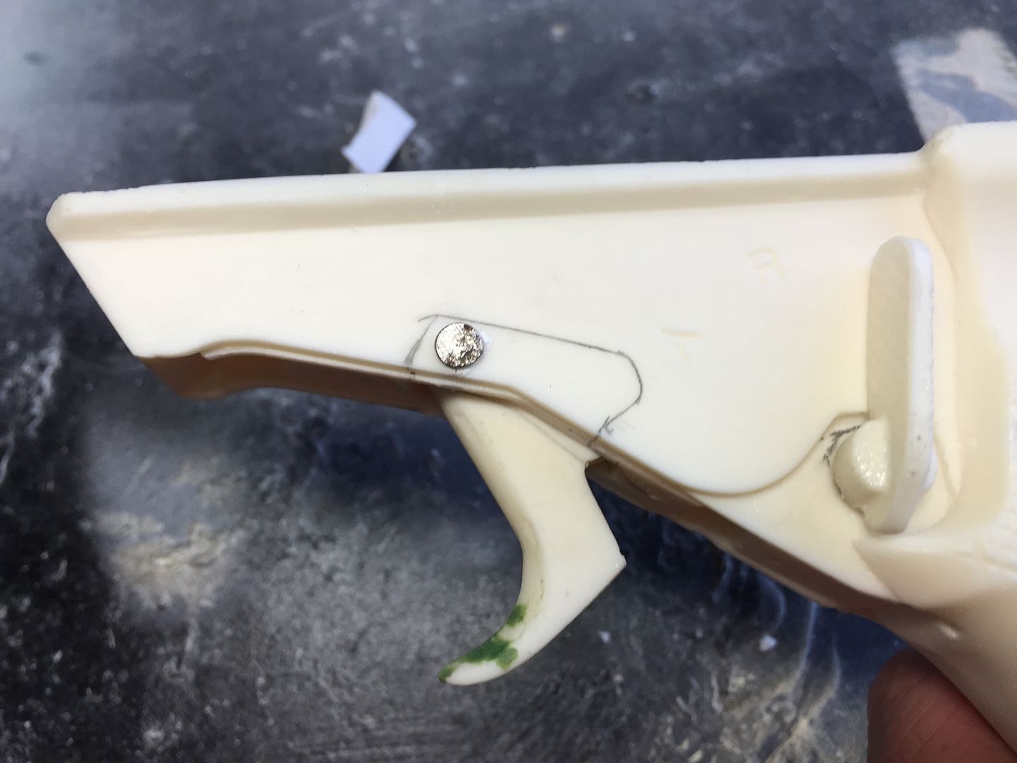
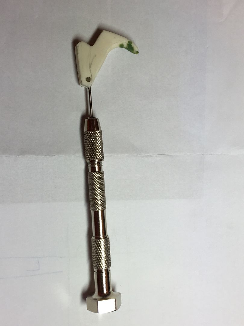
The final stage of the trigger modification, other than fitting the trigger guard, was to replace the temporary nail being used with some form or permanent pivot pin.
Basically this could be a smooth circular rod such as a nail, smooth part shank of a screw or in my case part of one of the solid steel rods taken from the counter (See page 1 of this build for details of the counter).
I decided that I intended to come up with a hidden fixing so that there were no visible signs of a pin/nail to the sides of the trigger housing.
To do this I measured the width of the trigger housing using digital callipers. What I then wanted was for the pivot pin to be inset 2mm at either side so that I could conceal it inside the trigger housing whilst at the same time having sufficient bearing.
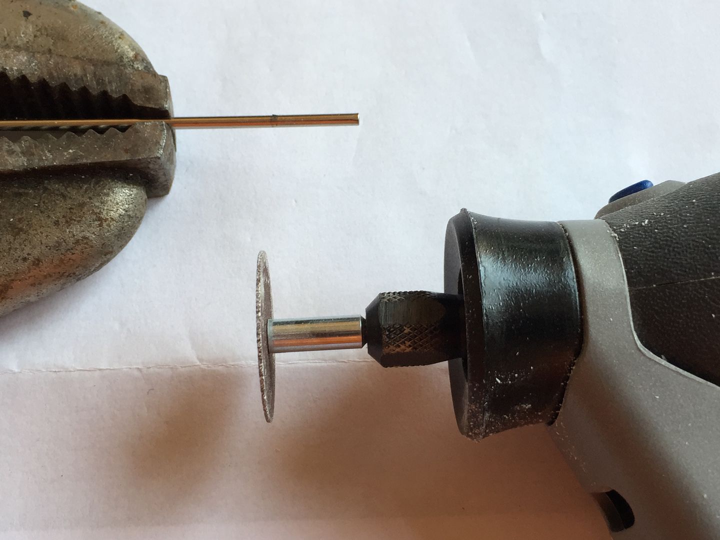
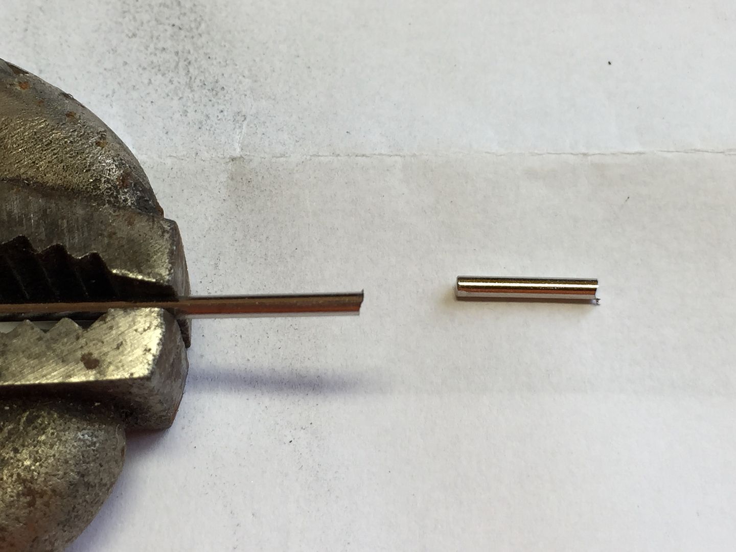
I then marked off a section of the counter rod and carefully cut it to length using a grinding disc on the Dremel.
A small amount of green stuff was then pushed in to one of the holes from the outside face of the trigger guard (There is no need to be neat with this as any excess is removed later).
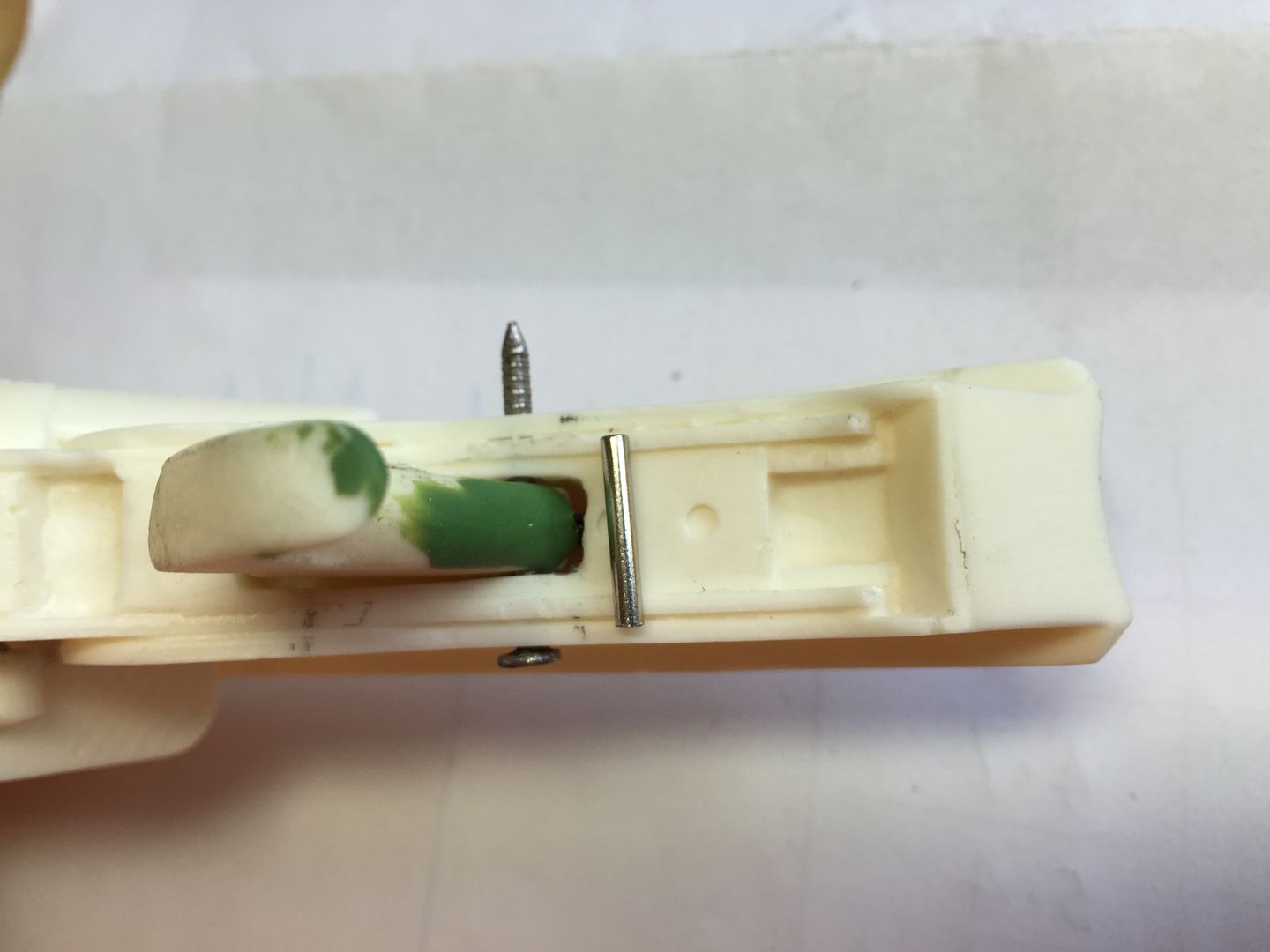
The pivot rod was then fed in from the other hole and pushed so that it is approximately 2mm below the surface of the outside face of the trigger guard.
Green stuff is then pushed in to the hole that the rod was installed from. At this stage the pin should be hidden from view however you will have 2 lumps of excess green stuff on the faces of the trigger housing.
Taking a flat surface, in my case just a plastic ruler that I had to hand, I scraped away the green stuff (before it had hardened).
Once hardened the trigger mechanism should be completely hidden.
-
1
-
-
Thanks Brian I'm glad that you liked it.
I wanted to try to come up with one or two ideas to add to the pool of knowledge available to others during there builds.
-
Thanks very much for your kind words and encouragement Tim I hope that I can continue to carry the touch though my build is only one of a good many excellent build threads some of which I think are unbelievable.
To be honest when I first received my resin kit I simply thought of gluing it all together and spraying with black paint however it is threads like this one, Tino's thread and more recently Twnbrother's thread amongst others that have inspired me to give it a go and make the blaster as realistic as I can manage.
-
2
-
-
Michael - Your power cylinders look amazing.
Your build thread is definitely one of the go to threads for anyone wanting to carry out a resin blaster build and incorporate a good number of modifications.
Keep up the great work.
-
1
-
-
Ok as mentioned in my post above I was looking for a method to allow more trigger movement (To be honest wanted to come up with something hopefully new to contribute to this community).
Therefore I have been working on an alternative method of achieving a working trigger.
Firstly I found, as is probably the case for most people, that the Duppydoo trigger is too wide to fit in to the trigger housing on the main model so used a mixture of careful work with a Dremel and filing to open up and smooth the width of the slot.
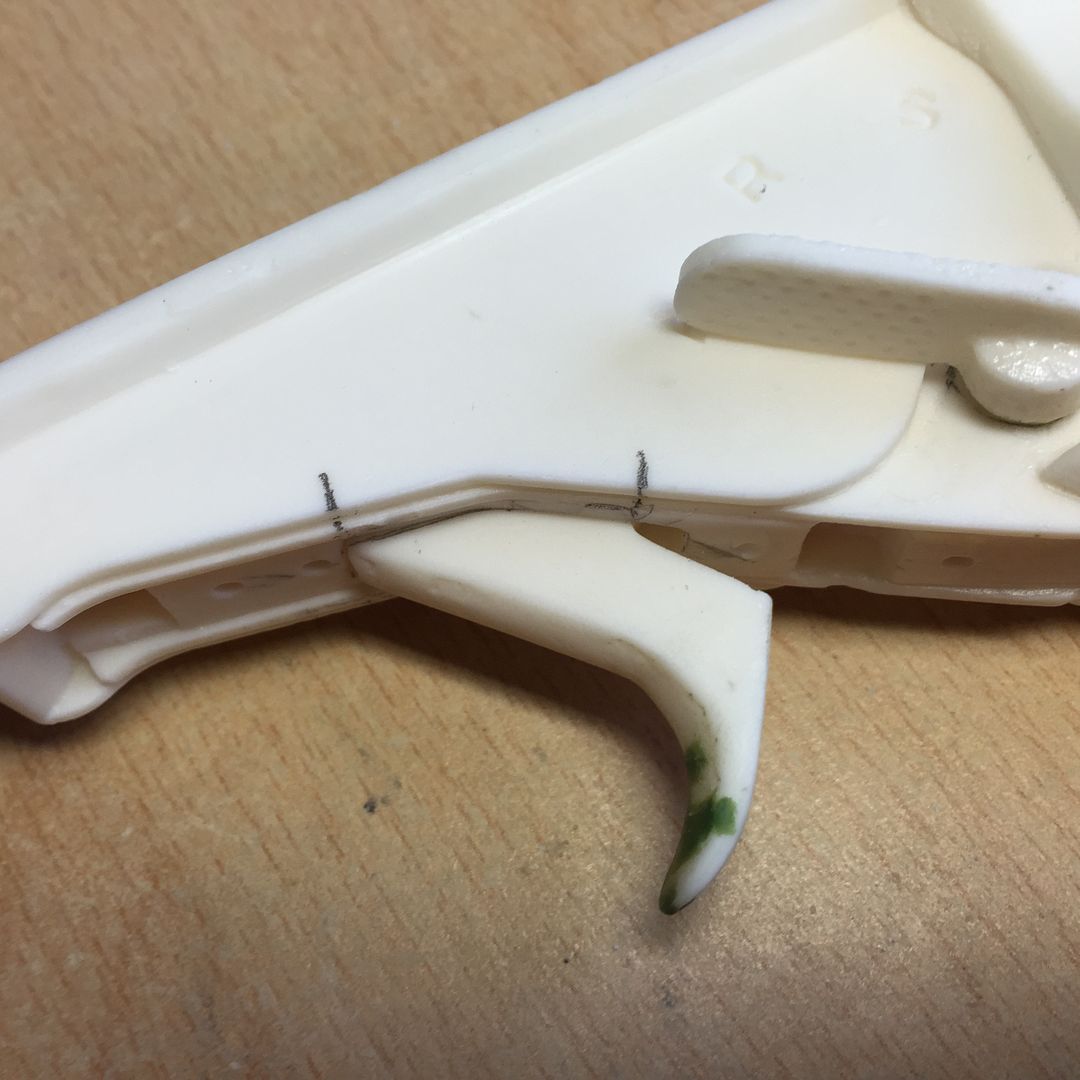
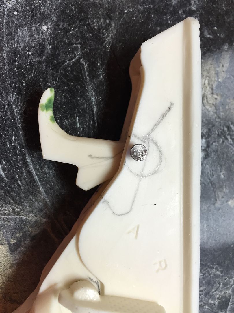
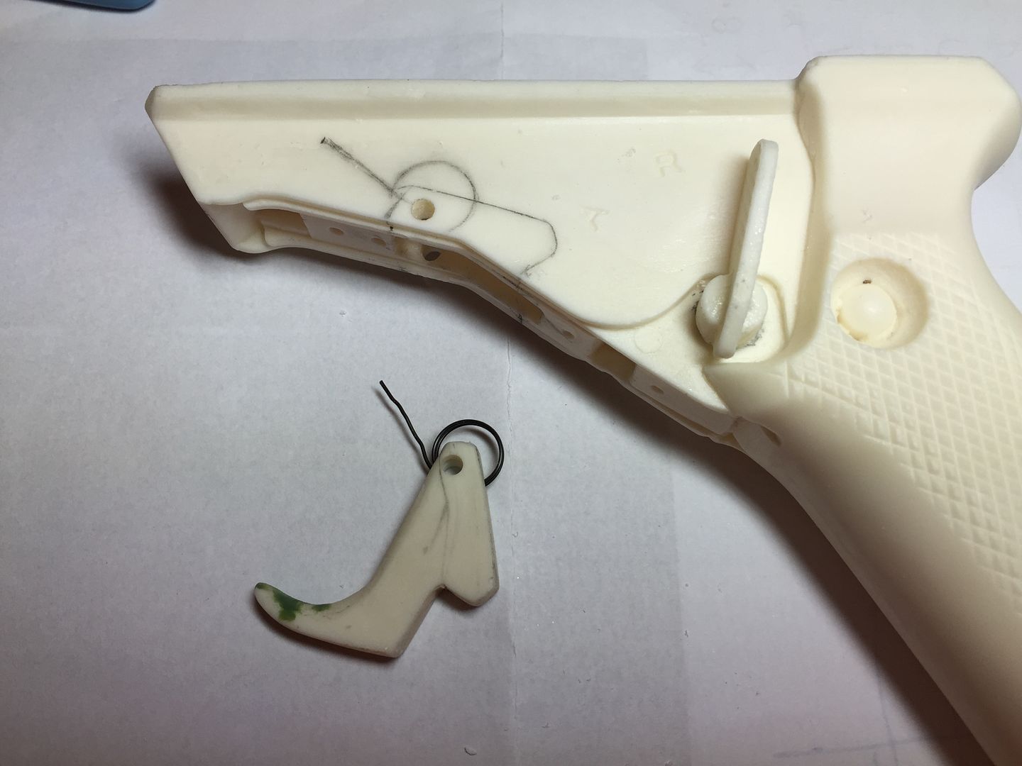
Once the slot was wide enough the trigger is positioned in it’s correct location and pencil marks are made where the trigger meets the housing. The trigger is then placed on top of the trigger housing, lined up with the pencil marks made and is then used as a template to draw the profile of the trigger which will be located within the main housing.
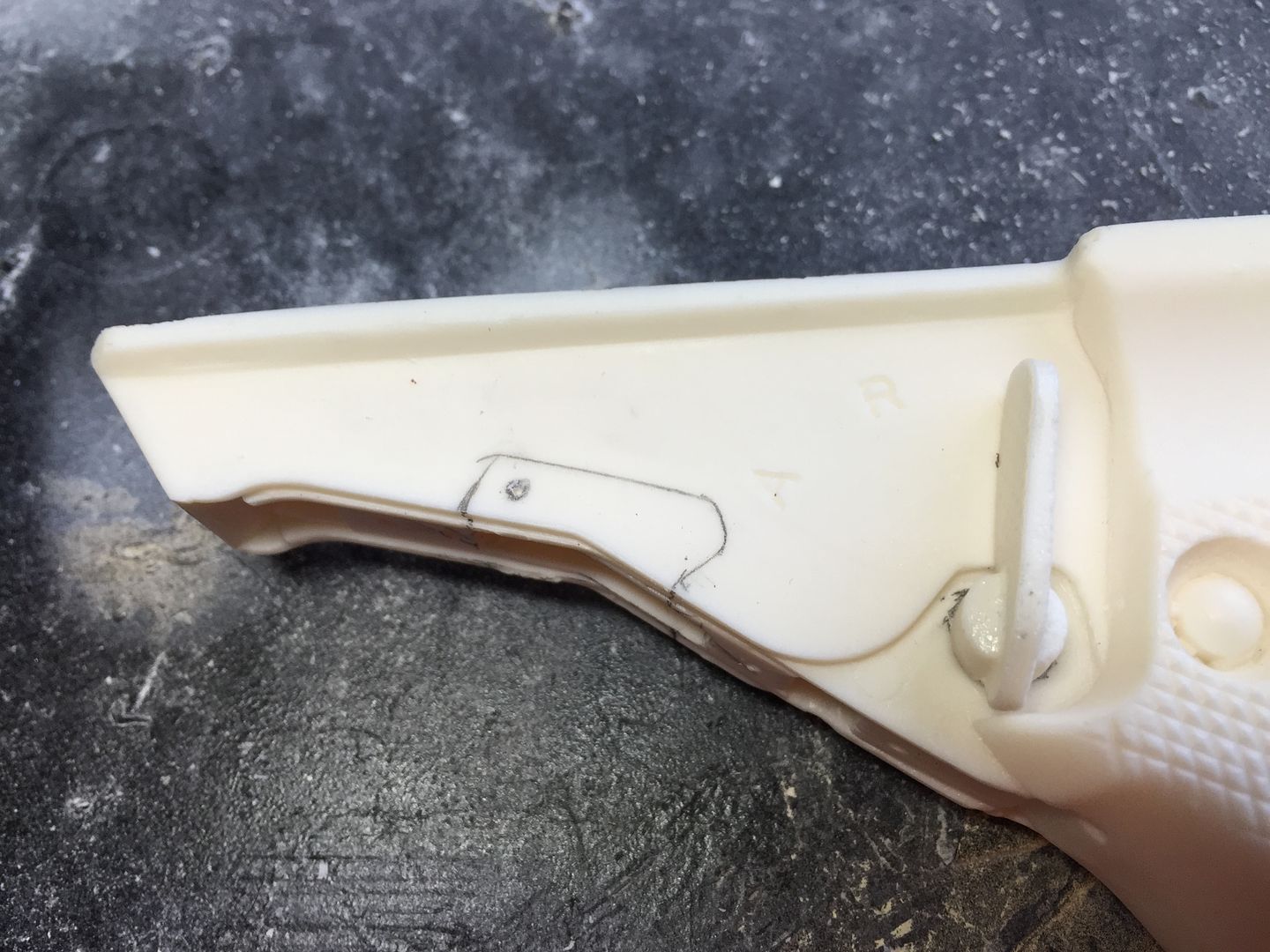
The location where the trigger is to rotate about i.e. where the pin will be located is then marked up and a Dremel is used to drill through the two walls of the main housing (I used a timber drill bit as these work very well to drill the resin). I placed the handle of the desk and drilled vertically downwards in one action.
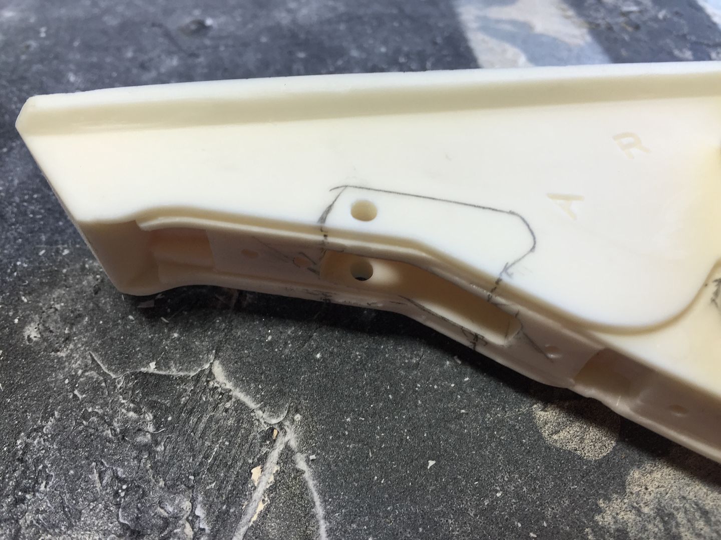
The trigger was then placed in the correct position within the housing and the drill was used to drill through the trigger using the holes that I had just drilled in the housing as a template. Once drilled a nail or similar item can be dropped through all 3 holes and the trigger moved to double check that it is not clashing with any material in the recess of the housing.
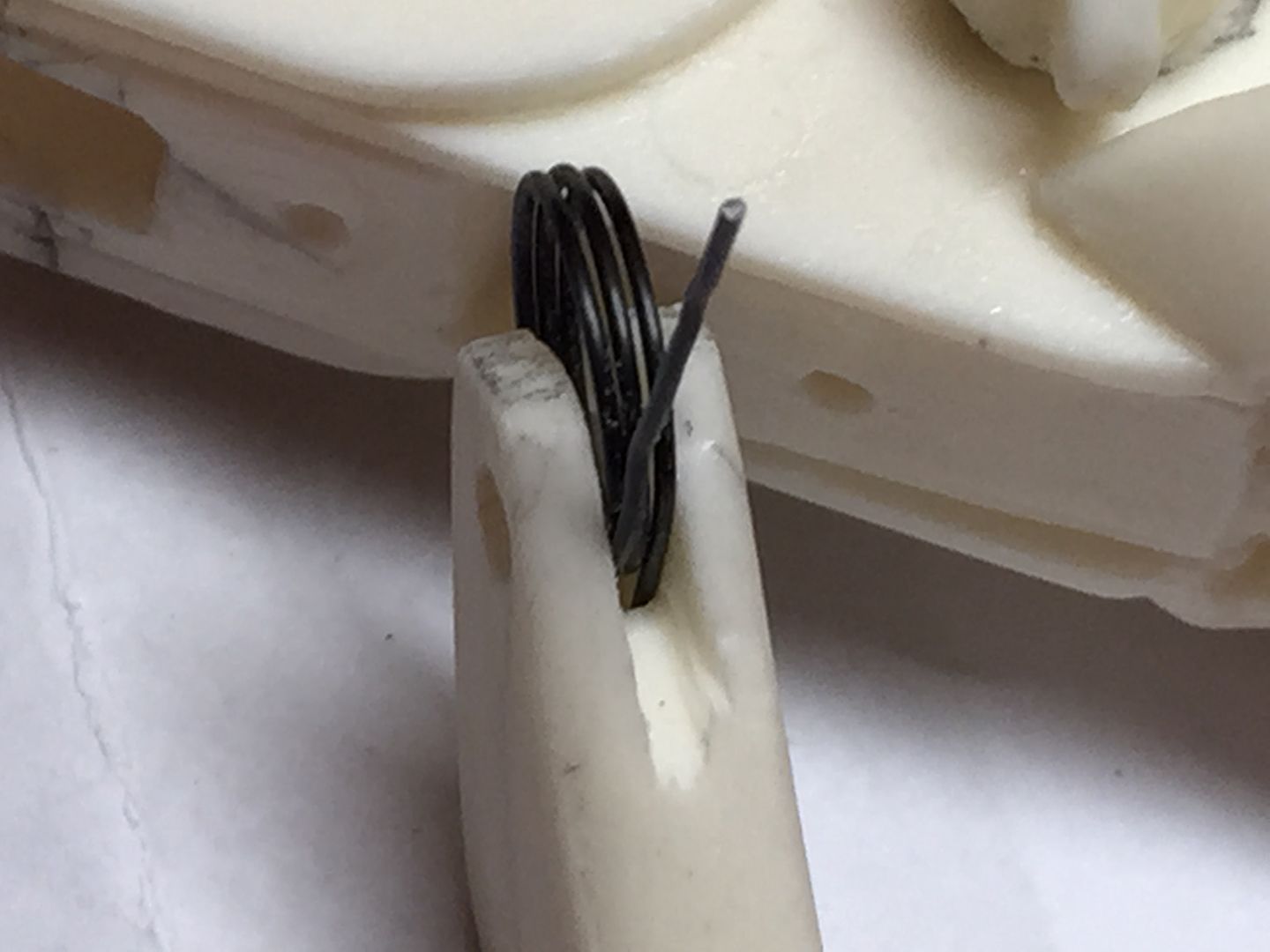
A slot was then carefully cut in the top of the trigger local to the holes that have just been drilled. The slot is provided to accommodate the spiral spring. The spiral spring I used was actually a stiff piece or wire coiled round 3 times with ‘tails’ on both ends and was actually part of the counter mechanism that I have taken apart. A coil spring could however be made by bending a suitably stiff piece of steel/brass etc.
The ‘spring’ is then placed on top of the trigger and housing and the ends of the profile of the spring drawn on the trigger and housing. This shows where inside the blaster the spring will be once installed.
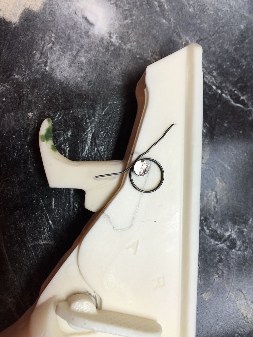
I checked that there was adequate room for the circular part of the coil within the housing before drilling out both the housing and trigger where the spring tails are to be fitted using a pin vice (Small handheld drill).
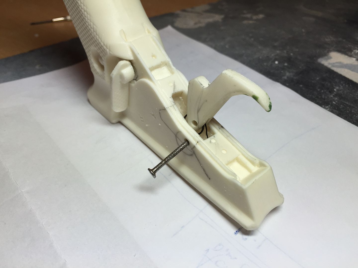
The spring can then be fitted in to the trigger and trigger housing by feeding the ‘tails’ of the spring in to the holes just drilled and once in position the nail can be fitted.
At this stage I had a working trigger and by slightly bending the spring to change the angle between the tails you can quickly and easily adjust the amount of trigger movement to suit your preference.
The last job at this stage was to repair the slot in the front of the trigger, where it would be visible, with some green stuff. Personally I find that once you have green stuff more or less where you want it you can smooth it very easily by wetting your finger and using your finger to get a smooth finish. Wetting your finger stops the green stuff sticking to them and therefore allows you to smooth out any ridges etc.
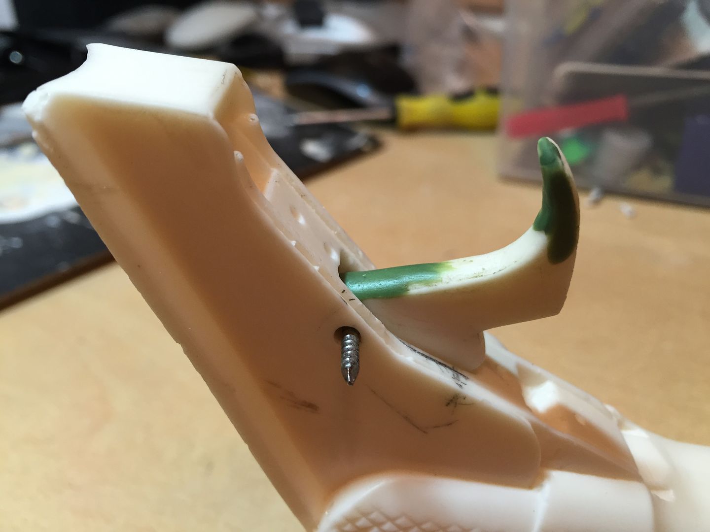
I will look at fixing and hiding the trigger pin when I get home later today.
-
2
-
-
I've been looking at a new way to achieve a working trigger.
This method has 3 particular features that I was looking to incorporate in to my build (The first feature was the one that I was particularly looking to develop as I wanted more travel than is achieved using the pen spring method.
1) It allows you to easily adjust the amount of trigger travel to suit your own preference.
2) it can provide a stiffer trigger mechanism compared to the biro spring method if preferred.
3) The force required to pull the trigger is constant.
I have a prototype version working at the moment so will look to post some pictures and notes showing what I have done tomorrow.
-
Dennis that really helps thanks very much.
I'll have to see if I can do it justice and come up with something that looks realistic.

Thrawns Guard's ANH E11 blaster build
in Build Threads Requireing Maintenance
Posted · Edited by Thrawn's guard
I came across some steel eyelets at the weekend and wondered what people’s opinion was with regard to using them on the folding stock to replace the resin rivets. I have taken some comparison photos below to clarify what I mean.
They seem to be a good match for the end of the stock but less so for the other detail.