

Thrawn's guard
-
Posts
479 -
Joined
-
Last visited
-
Days Won
9
Content Type
Profiles
Forums
Gallery
Articles
Media Demo
Posts posted by Thrawn's guard
-
-
I did manage to get a little extra done yesterday namely the installation of the wire to the front of the power cylinders though this proved to be a little fiddly. I removed the wires from the front of the fuses one by one, bent them to shape, (so that they would pass from the front of the fuse to the holes in the wing plate), before cutting them to length.
I then carefully applied a small amount of glue to the ends of the wire (the ends of the wire were inserted in to the front of the fuse and wing plate).
-
 1
1
-
-
Thanks for the kind words guys I'm really pleased with what I have been able to do so far and glad that others are finding it of use/interest.
-
I also couldn't wait to see how the power cylinders were going to look like once installed on the blaster therefore I had a very quick test for as shown in the photographs below.
-
2
-
-
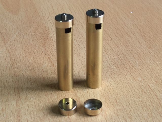
Looking around the house for something which could be used to replicate this detail I came across some standard UK mains plug fuses. These provide me with the size of cylinder I was looking for as well as being very inexpensive.
Another advantage of using these fuses is that they come with ‘dimple’ in the centre of the end caps as shown in the photograph below (Dimple on the left and drilled end cap on the right). This is great for locating the drill correctly when forming the hole in the cap.
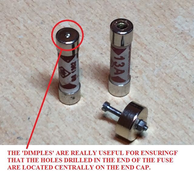
Taking a 3mm diameter drill bit I carefully drilled a hole in the end cap, (See the fuse on the right in the photograph above), and removed the inside of the fuse. The drill diameter was chosen to be just slightly larger than the diameter of the bolt head so that the bolt could be dropped in to the end of the fuse.
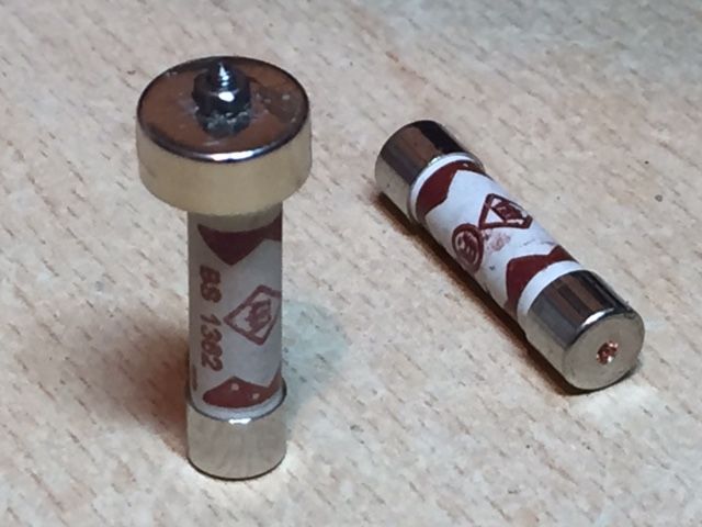
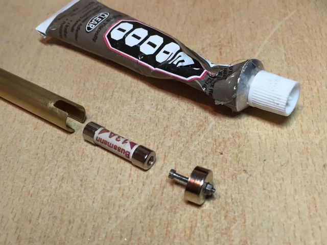
The photograph below shows how these items are fitted together to form the rear of the power cylinder detail.
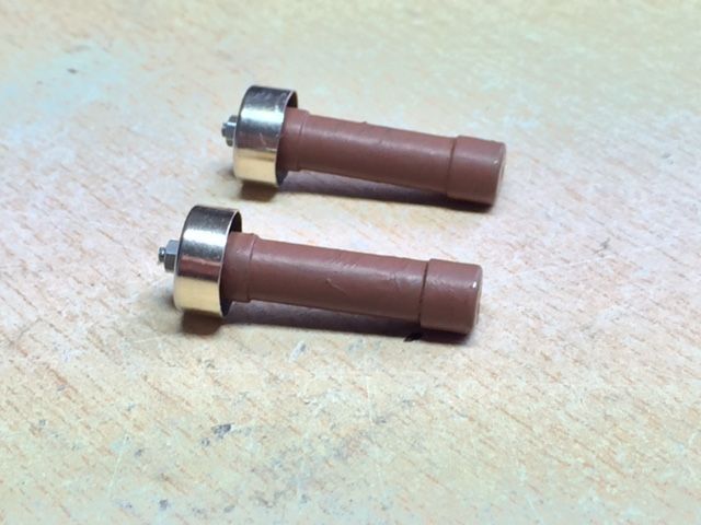
The final task was to paint the fuse with a rust coloured brown paint. You will only see this if you look carefully but it was a small additional detail that I wanted to include.
-
1
-
-
Christian you have done an amazing job with your blaster build. I also love the stand.
-
Hey Mike I used the following for the power cylinders:-
1) K&S 135 brass tube 3/8 x 12" (9.52mm outer diameter).
2) AGU 40A car audio glass tube fuses (1.5" x 0.4" / 38mm x 10mm).
Let me know if you have problems finding them as I should be able to send you the links or post some. I got the brass tube from eBay and the fuses from Amazon.
I should also have some further update photos to post sometime tomorrow.
-
1
-
-
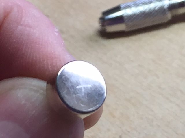
I measured the outside diameter of the end caps,(10.2mm), and then set some digital callipers to half this distance, (5.1mm), in order to be able to find the centre point of the end cap.
Using the metal ‘prongs’ on the callipers I gently marked a line on the end of the end cap, rotated it approximately 90 degrees and then repeated the process. This gave me a cross mark as can be seen on the photograph below which accurately indicates the centre point.
Once I had the centre located I carefully drilled a small pilot hole in the end caps.
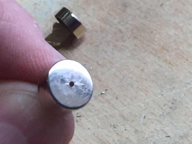
I then opened up this pilot hole to a diameter just slightly larger than then diameter of the bolt thread (The diameter of the bolt thread used was 1.6mm).
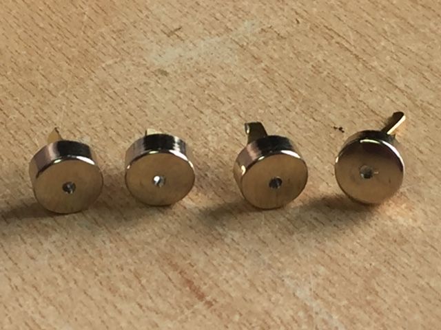
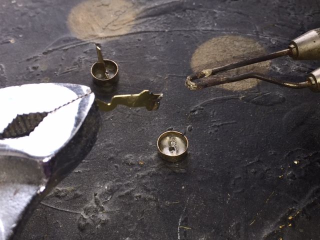
Aaron (usaeatt2), previously advised me that if I was to heat up the end caps the solder melts and the cap just falls off the remainder of the metal fuse element. I don’t have a blow touch however I do have a soldering iron so decided to have a go removing the elements using this.
All I did here was hold the end of the fuse element with a plumbers spanned whilst I heated up the solder and as Aaron suggested once they were hot enough they simply fell off. Thanks for the tip Aaron it proved both easy and prevented me from possibly damaging the end caps trying to remove the elements.
Finally I trial fitted the nuts and bolts to one end of the power cylinders (Nothing is glued together at this stage). If anyone has any tips or suggestions at this point it would be much appreciated before I start gluing things together.
-
1
-
-
Thanks Aaron it is good fun and even better when you have something at the end that you are happy with.
-
Daniel I have not looked at modifying these and am not sure which tend to be modified however I'm sure someone will come along soon who will be able to advise you.
-
The links don't appear to be working.
-
Credit where credit is due Tino has done a great job making the 3 capacitors in his “How to make your Power Cylinders more accurate” thread so rather than try to reinvent the wheel I am going to use this as the basis for my build.
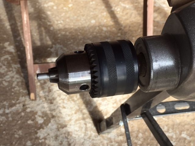
The first job is to take the 5mm diameter aluminium rods provided in Tinos completion set and make the curved profile to the ends. In order to do this I clamped my hand drill to my workbench so that I could operate the trigger with my left hand.
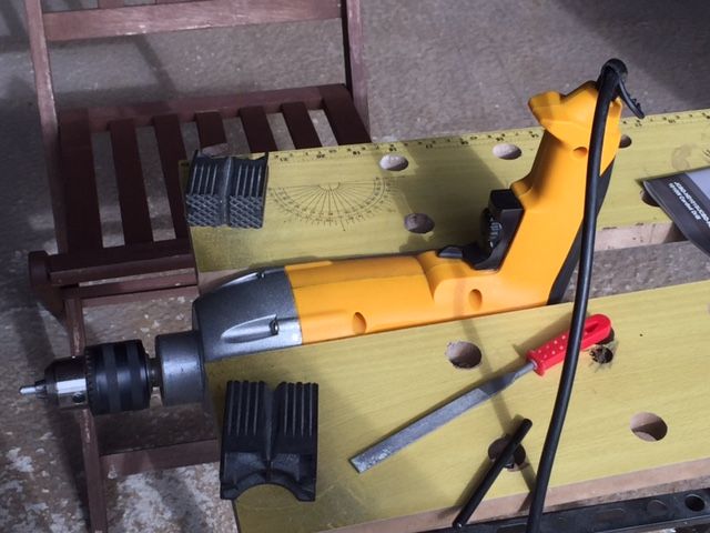
The aluminium cylinders were then placed in the drill chuck and a small hand file used to shape the ends of the cylinders whilst the drill is operating.
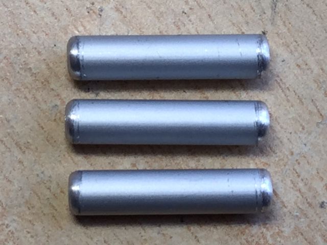
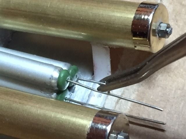
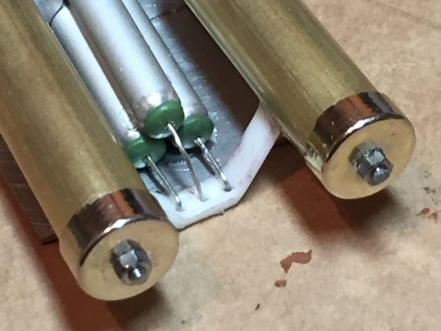
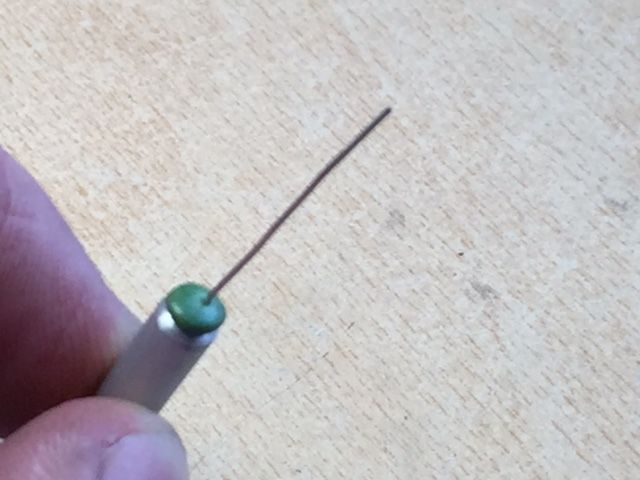
Once that I was happy with the profile on each end of the cylinders I mixed a small amount of green stuff to form in to the ‘caps’.
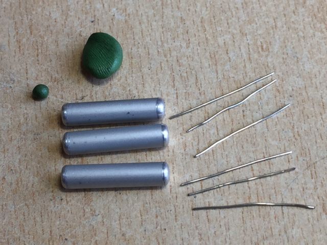
This was achieved by rolling a small amount of green stuff, approximately a 2mm diameter sphere, placing it centrally on the end of each cylinder and then genially pushing it so that the overall thickness of the ’caps’ are about 1mm. Wetting your fingers before pushing the spheres in to shape will stop the green stuff sticking to your finger rather than the end of the cylinder.
When I was happy with the shape of the caps I cut six 25mm lengths of 0.45mm diameter wire, (fuse wire could be used for this purpose), and pushed one piece centrally in to each of the caps. I can cut this wire to length later but thought it better to have more than is needed rather then less.
This is what I ended up with.
-
1
-
-
I'm glad that you like them Mike.
I did try to see if I could get a set of Andy's resin power cylinders but wasn't successful so thought that I'd give them a go myself.
To be honest I am glad that I did as I am enjoying the process. If nothing else it is also prolonging my build and I'm not sure what i will do with my time once it is complete......perhaps build a biker scout pistol, light-sabre hilt or perhaps maybe even some armour.
-
1
-
-
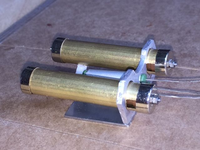
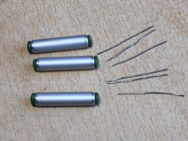
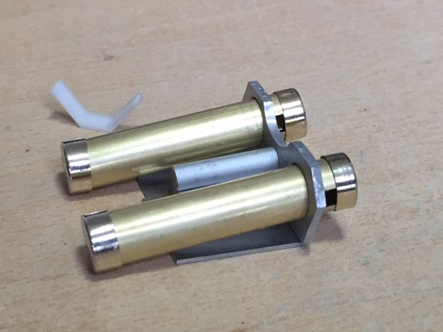
I couldn't resist having a quick tried fit to see how things are coming together. It seems to be working out OK so far but I still have a bit of work to do before I have them complete.
Here are a couple of quick pictures to show you what I have so far.
-
1
-
-
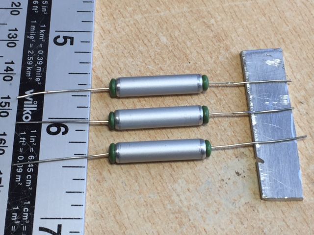
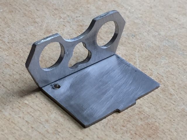
Today I had a go at making my backing plate from a strip of aluminium.
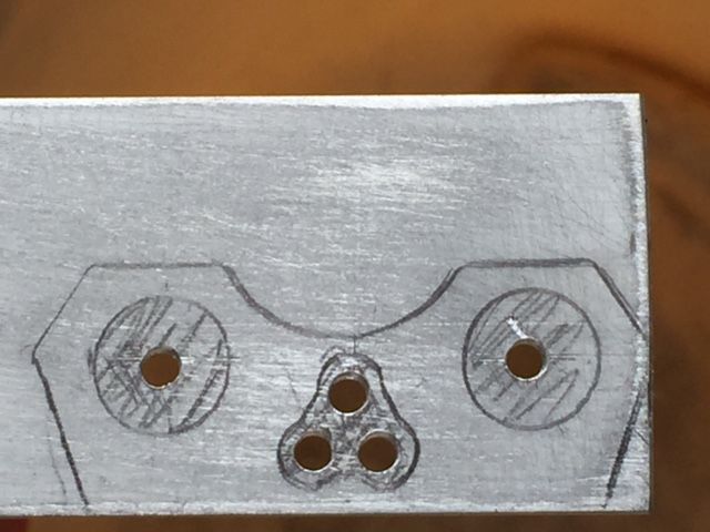
Taking the aluminium strip that I marked out in my earlier post I carefully marked out the centre of each of the 10mm diameter holes for the power cylinders to fit through and also the three 5mm diameter holes for the fuses to fit through. Once that I was happy I had marked them out correctly I used a sharp point to mark out a small starter hole (which will help keep the drill bit located correctly).
I then slowly drilled out a 2.5mm diameter hole at each of these locations.
The holes were then drilled out fully using the correct drill bits.
The outer shape of the backing plate was then cut out using a cutting disk on a rotary drill.
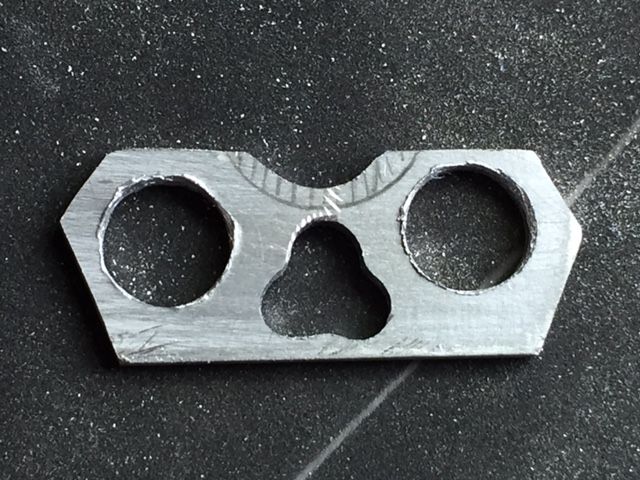
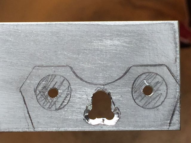
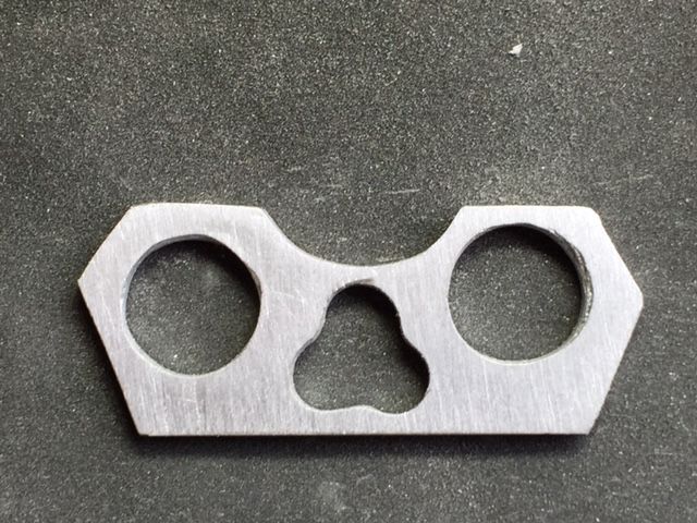
Finally a combination of a sanding tool and a circular hand file were used to form the circular recess in the top of the back plate. The edges were then cleaned up using sandpaper,
-
1
-
-
Nice work Richard.<br><br><br>
With regard to the trigger fixing nail I would suggest cutting the head off and shortening the shaft of the nail to just less than the width of the trigger assembly.<br><br><br>
You can then install and cover both ends with green stuff and once painted you won't be able to see a thing.<br><br><br>
Have a look at page 4 of my build if what I have explained is unclear.
-
Just a short update this time to show what I have been able to do after getting home from work.
I have cut the brass tube to length, (46mm), with a cutting disc on a rotary drill before test fitting the end caps.
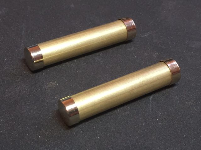
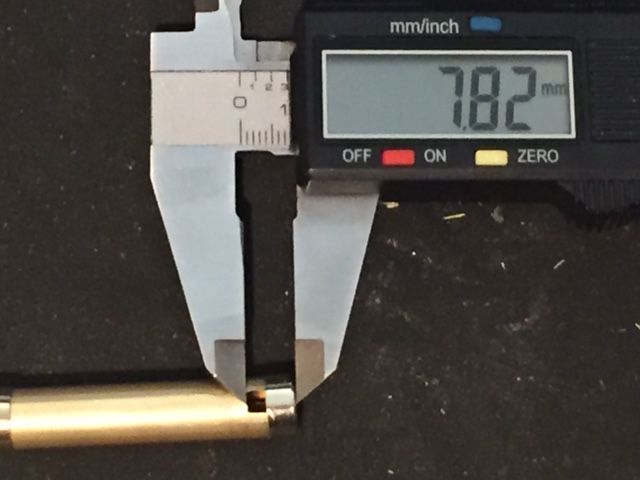
Next I needed to form the slots at the rear end of the cylinders (7.3mm long and 3.5mm wide). Firstly I marked a line around the brass cylinder 7.3mm from the end using digital callipers. Then taking a circular cutting disk I carefully cut a thin slot out in both walls of the rod to the full length (7.3mm),.
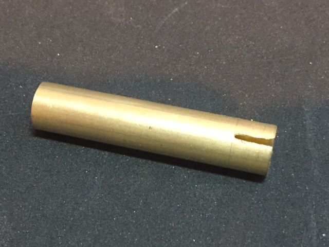
The same cutting disk was then used to gradually widen the slots until they were 3.5mm wide (This distance was checked regularly with the callipers). The photograph below shows the cylinders with the notches cut at one end and the end caps loosely placed I to position.
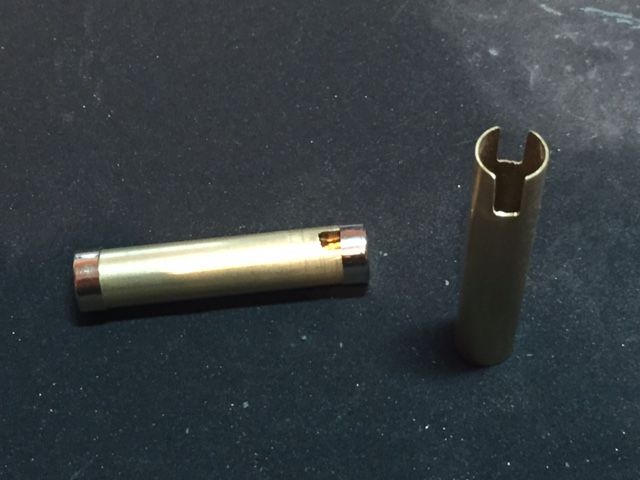
I also show below the distance from the end of the cap to the end of the slot (The caps extend the length of the brass rod by 0.5mm at each end).
-
1
-
-
Great tip about heating the end caps to get them off the glass tube Aaron.
If I make some more at some stage I'll give that a go.
We all share and learn from each other which is what is so great about the FISD.
-
In order to drill out the holes in the backing plate I will need to use my drill in the garage but need the daylight as I don’t yet have any lighting in there so this task will have to wait until the weekend.
As a result I thought that I’d do a little work or the power cylinders themselves namely forming the end caps.
I took one of the large fuses and carefully marked out a 4.3mm wide section to the end of the metal caps. A rotary drill was then used with a cutting disc to carefully cut through the metal and glass below.
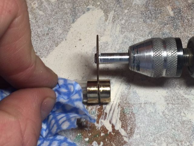
After I had cut the first three I realised that the easiest way to mark out the end cap and ensure that you marking could be easily seen was to wrap a small amount of masking tape around the end of the fuse, set a pair of callipers to 4.3mm and use the ‘teeth’ to gently mark out on the masking tape.
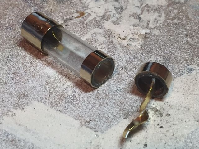
The most difficult part of the task however was to remove the small section of cylindrical glass left in the end of the cap without causing any damage.
Finally I test fitted the end cap of the brass tube.
-
1
-
-
Thanks very much for posting these images Aaron and for the offer to send some resistors.
I'm pretty sure that I should be able to get some but I very much appreciate the offer.
-
Ian I understand that the RS prop master helmets are the most accurate helmets as they are cast from an original screen used helmet. Trooper masters helmet is also known as being a very accurate option.
-
Jared - You have carried out some really impressive work here with great attention to detail. I particularly like what you have done with the magazine catch assembly.
As I have said before I am constantly amazed at the continued improvement on modifications that can be made to resin kit builds this build being a prime example.
-
1
-
-
Thanks Aaron though I may however have misidentified the parts I was querying (Though the picture provided above is also of great help).
I was referring to the small cylindrical items Tino makes from grey plastic offcuts from a model kit as shown in the top right picture borrowed from his power cylinder modification tutorial shown below.
-
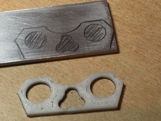
The next step was to look at making the back plate.
For this I am looking at using some thin aluminium strip (previously an aluminium ruler).
I used a rough 3D printed version as a template to mark out the profile and holes using a mechanical pencil and will look to start shaping and drilling hopefully tonight.
-
My power cylinder build has been going a little slow as I have had family staying however the good news is that I should now have more time to work on them and get them finished.
I do have one quick question if anyone knows the answer. With regard to the small resistors which are located next to the textile insulated wire does anyone know the exact length and diameter ?
As far as I can see we only have reference pictures, which I can use to get something about the correct size, but thought it worthwhile checking just in case I have missed it somewhere.
Thrawns Guard's ANH E11 blaster build
in Build Threads Requireing Maintenance
Posted · Edited by Thrawn's guard
I know what you mean about the paint Brian but I'm sure once I do apply the paint it will be OK.
Hi Ian I'll double check the height but am pretty sure that is is correct. If I do need to lower it I can connect the base plate to the side of the end plate which will drop it down in the region of 1.5mm.