

Thrawn's guard
-
Posts
479 -
Joined
-
Last visited
-
Days Won
9
Content Type
Profiles
Forums
Gallery
Articles
Media Demo
Posts posted by Thrawn's guard
-
-
I love the scope effect Michael.
You blaster as a whole is really progressing well.
Is the recticle an official E11 design or is it one the you chose ?
Is there even a screen used or official recticle ?
-
Wow great looking blaster build and stand Dan.
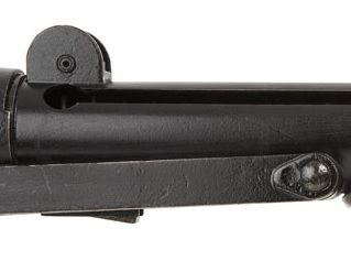
The only minor comment that i have, and you may decide that it is not of concern to you, is that the fixings used to attach the folding stock to the main body near the trigger assembly are smooth domes on a real Sterling.
If you do decide to tweak this you should be able to fill the screw heads in with some green stuff, smooth and apply a little paint.
I think that the stand really presents the gun fantastically.
-
Nice work on your build so far Joe.
The repair to the T tracks should be quite straightforward so don't worry about it.
When carrying out repairs I tend to mould the green stuff roughly in to the correct shape but leave it projecting slightly more than will be needed. Once it has set you can then file and sand to get a smooth match with the resin.
Another technique though requiring more accuracy when sculpting the green stuff is to wet it while it is still 'soft' and smooth it with a flat edge or finger.
I must also say that I particularly interested in how well you manage to integrate the electronics.
-
Thanks guys for the positive feedback and kind words. I'm just happy to be able to try to contribute to this great community.
I came across the E11 blaster reference thread late last night and quickly flicked through it to see what was there. I intend to read through it thoroughly today as it looked just what you need as an additional aid and easy point of reference when putting your blaster together.
@ Brian - The rivet detail that you referred me to above for the rear sight is exactly what I was looking to produce so thank you very much.
-
 1
1
-
-
This is a fantastic reference resource and must have taken untold hours to put together so thank you very much for your amazing amount of effort.
Once more a great example of troopers helping troopers......and in my case at least a trainee trooper.
-
6
-
-
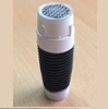
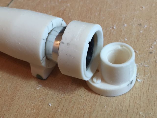
At this stage it can be seen that the problem encountered is that the scope is offset so that light can't pass directly though. This picture shows what you will see when you join the smaller end of the scope to the central section.
In order to overcome this I took the 2 prisms from the monocular and set about planning how I could use these to bend the light around the step in the scope.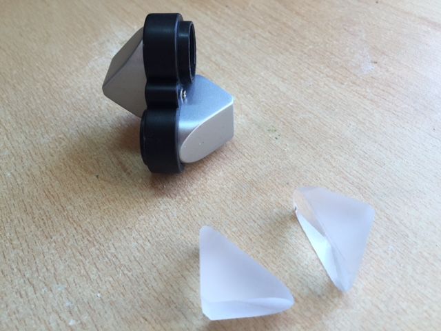
I have provided below a picture of the theory of how this works to hopefully clarify what I am trying to describe.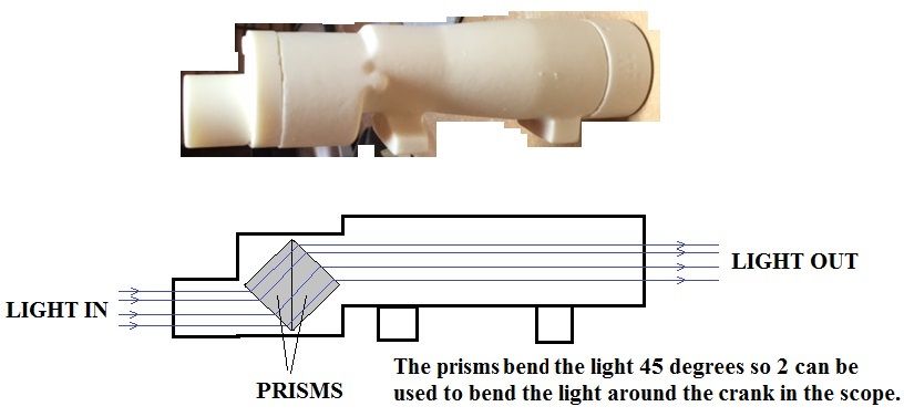
The main issue here is that the prisms are almost as long as the scope diameter so care is required when installing them (There is not much room for error….though there is green stuff).
Taking one of the prisms and placing it on top of the central section of the resin scope a fine pencil can be used to mark out the profile of the prism. This shows the shape and size of the recess that is required to be made in the central section of the scope.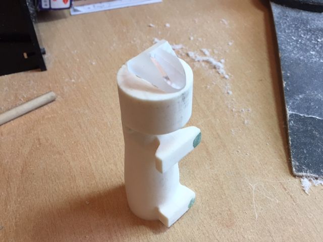
Taking a Dremel I carefully started to remove resin using the pencil line as a guide.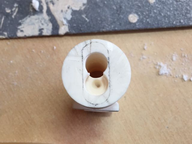

NOTE - Care must be taken to not drill through the kink in the scope (This kink also restricts the depth that the prisms can be embedded in the scope).
After much drilling and sanding I reached the stage where I was unable to excavate any further without risk of making a hole in the wall of the scope (If it is possible to use slightly smaller prisms this would be an easier task).
The 2 prisms are then dropped in to position remembering to clean then both before installing then otherwise you will have finger prints when looking through the scope.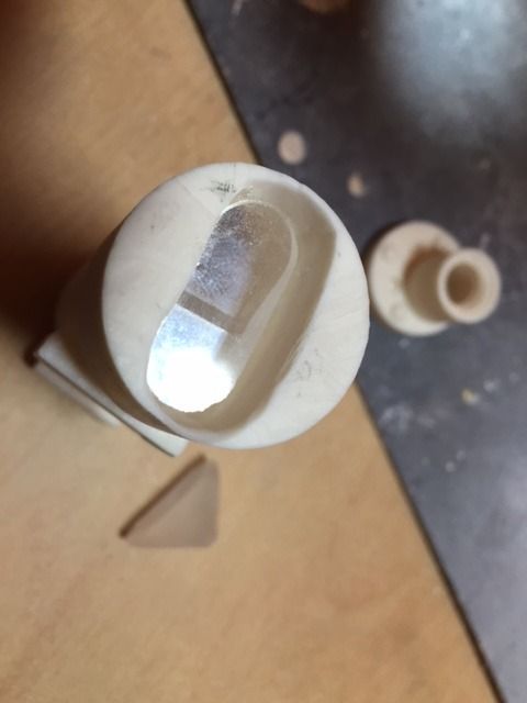
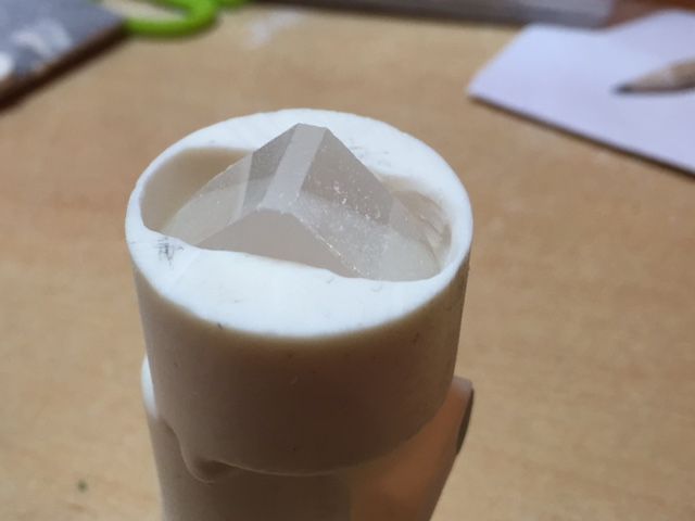
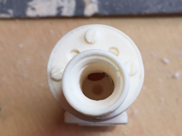
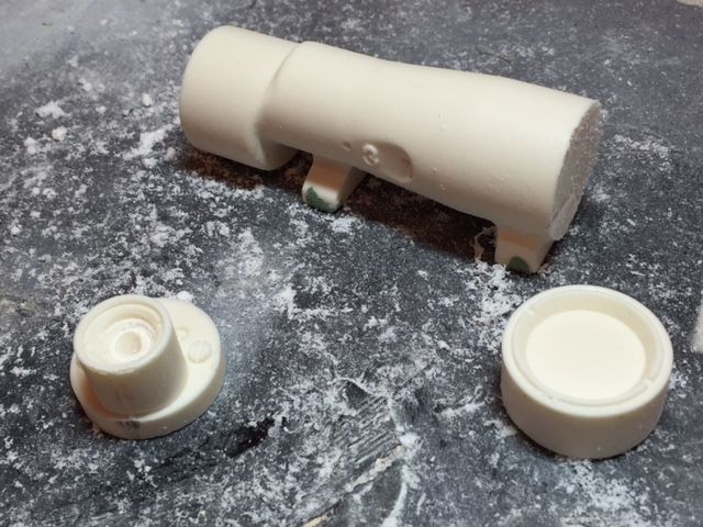
As can be seen from the photograph above the ‘corner’ of the second prism to be installed projects out of the central section. Therefore the solution to ensure that the prisms can be installed is to open out a small section of the end scope section (See below).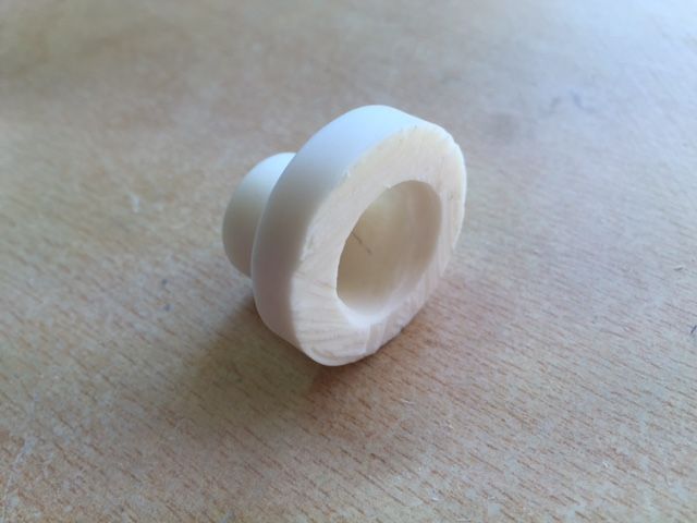
We now have the 3 sections of the scope ready to be trial fitted. I installed the small lens from the monocular in to the small lens housing in the resin scope and then fitted the 3 sections together temporarily sticking them together with some masking tape.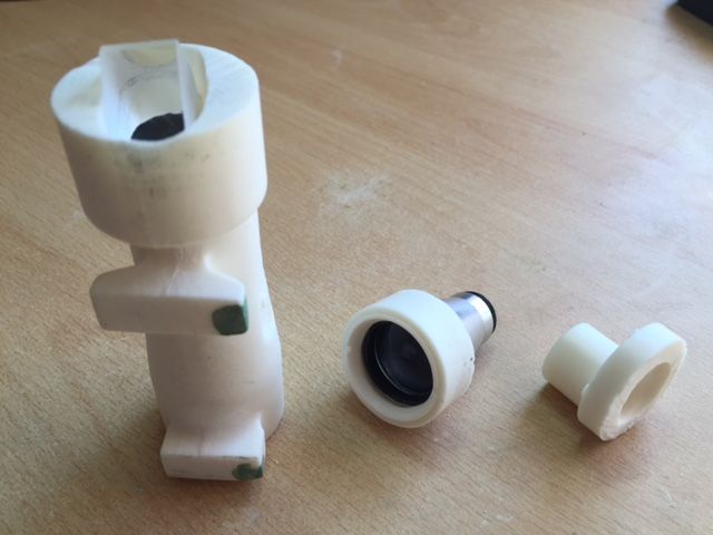
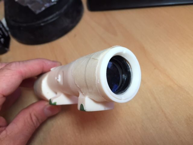
This was where I got to when I took the picture through the scope that I posted earlier. Nothing has been glued as yet as I need to be able to open up the scope to install the crosshairs once I have sorted that out.
I will post further updates as I progress.-
4
-
-
The scope build has turned out to be a project in itself however I have been enjoying the challenge.
The next stage of the scope modification uses parts taken from the monocular shown on the first page of this thread and as far as I am aware has not been done previously.
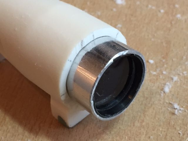
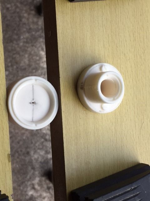
I decided to incorporate the large lens housing from the monocular as this would hold the lens firmly in place and also provide the ‘correct’ smooth appearance when looking through the scope.
In order to locate the lens in the correct position in the scope I did however need to remove the front end of the housing using a Dremel and smooth it off/removing sharp edges using a fine sand paper.
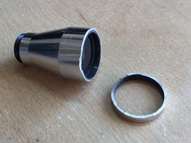
Next I needed to tidy up the large end of the resin scope but also ensure that I retained a small lip to prevent the lens housing from falling out. This was achieved by gently using a sanding bit on the Dremel and checking the fit on a regular basis.
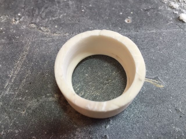
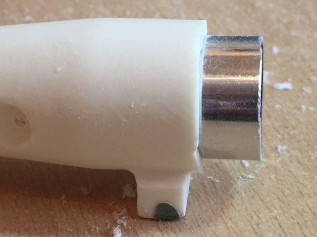
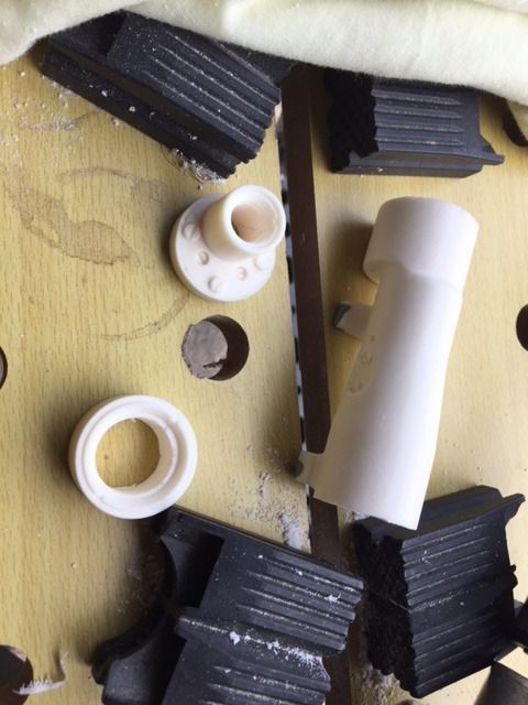
The rear section of the scope housing also needs to be embedded in to the central section of the resin scope but at first wouldn't fit.
Again I gently used a sanding bit on a Dremel to enlarge the diameter of the opening in the resin scope to allow me to fit the lens housing in place. If done carefully a tight fit that doesn't require any gluing can be achieved. I didn't want to glue anything in because I would like the option to be able to tweak the scope and allow access for later work.
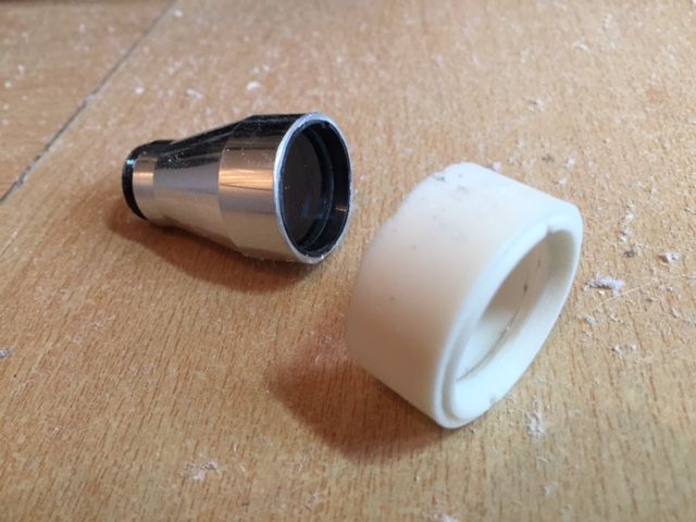
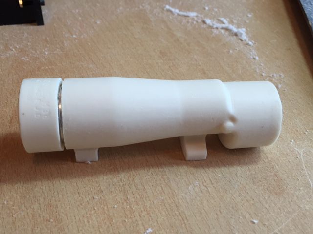
Once this is complete the 3 sections of the scope can be trial fitted.
-
2
-
-
Nice work on the blaster Josh.
-
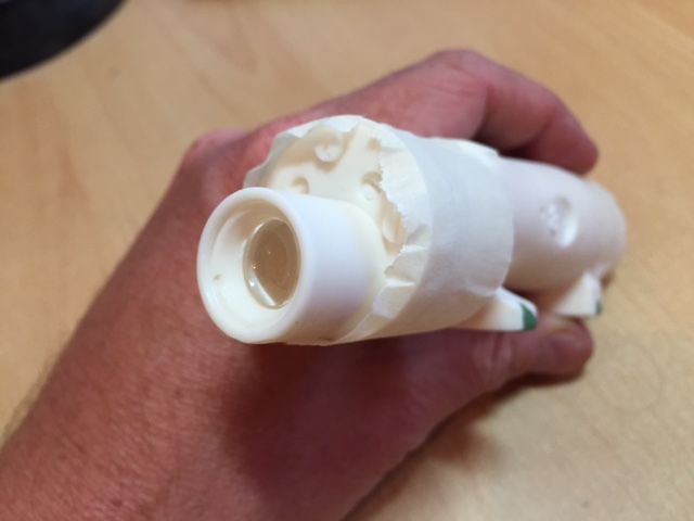
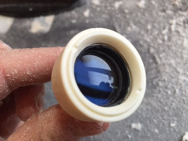
I will post full deals later on what I have been working on and how I did it however here is a quick teaser of the trial assembled scope.
This is not the best photograph however it was difficult to hold the scope, the phone and get the phone to focus on the correct part whilst looking directly through the scope but it does give a good idea of how this is working.
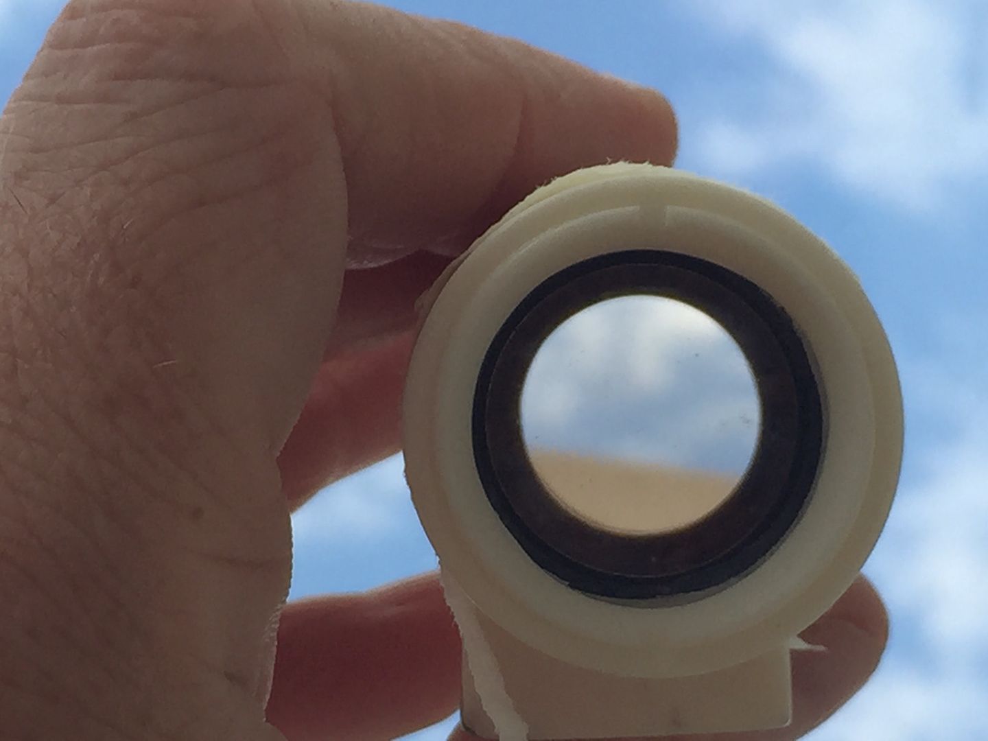
I incorrectly stated earlier that I had used a mirror system to get the light to pass through the scope (I actually used 2 glass prisms).
Images viewed through the scope are actually in focus however they are upside-down. I have been trying to flip the image the correct way around but due to the limited space in the scope have been struggling. I did manage to flip the image the correct way around but found that I couldn't get it to focus correctly when I introduced an additional lens.
That said I am very pleased with the effect.
I do have two quick questions if anyone is able to help.
1) Does anyone know if there is a screen accurate cross-hair or do people generally come up with there own ?
2) I have also tested a prototype cross-hair effect which seems to work well but I need to think about how I go about producing the final version. Effectively I need to produce a good quality cross-hair on a thin circular sheet of glass or other transparent material. I do have an idea myself but don't yet know if it will work out. Does anyone have any suggestions for this ?
-
1
-
-
Well I have made some good progress with the scope but finished too later to post pictures so I will do that tomorrow.
What I have been working on is how to get light to pass through the scope in a more realistic way. The problem is that because the scope is cranked you do not look directly through a single cylinder and as a result because the scope is staggered you get a very limited amount of light passing through.
I have however managed to come up with a system ofmirrorsprisms which reflect the light around this step in the scope.
Initial results look very promising.
I will be keen to see what people's thoughts and feedback is on what I have done once I post pictures.-
2
-
-
Thanks for the feedback guys it is very much appreciated.
Do we know which were 'screen used' ?
EDIT - I have an idea how to possibly recreate the sight rivet detail shown in the picture I posted above. I'll look in to this a little further.
-
Michael - I have also seen both of these but am not sure which is correct (Unless both are correct for Sterlings manufactured in different years i,e. unless the design changed from one to another).
EDIT - I found this on the photo reference gallery.
-
Can anyone post a close up picture of the rear sight of a real Sterling ?
I would like to upgrade the side bolt detail but want to make sure that what I do is as accurate as possible.
-
As promised in my earlier post here is my latest update showing work that I have done so far on the scope.
I almost had to force myself to start cutting in to it as I didn't want to have a major disaster on my hands however once I got started things felt much better.
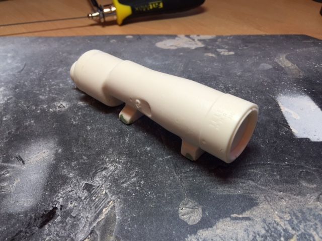
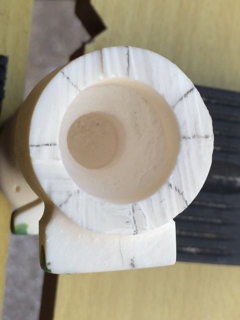
First of all I used a fine cutting disk on my Dremel to cut around the end of the scope closest to where the small lens will be installed. I needed to finish off the cut with a coping saw because the cutting disc wasn't large enough to cut all the way through.
I decided that the best place to cut the scope was where the scope actually has a joint that way when I come to put it all back together I will be able to properly hide the fact that I have cut it open.
I then repeated the same process at the end of the scope towards the large lens.
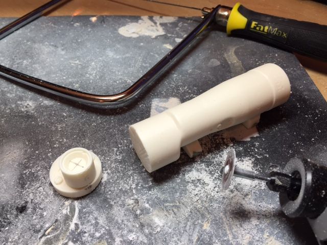
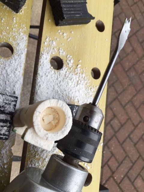
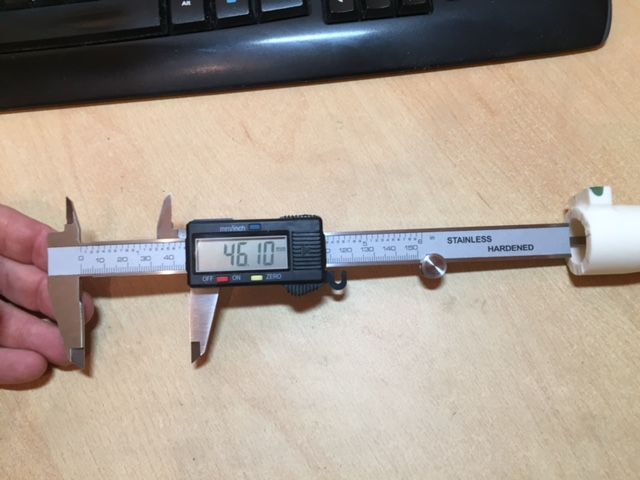
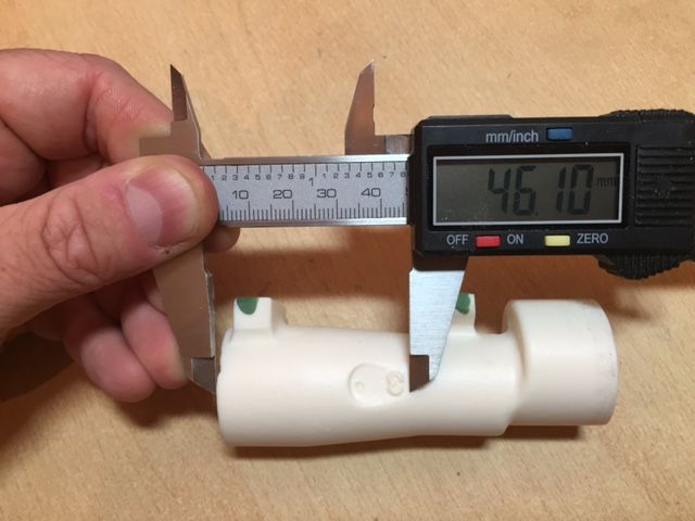
The next step was a little tricky as I don't have a vice (yet). I placed the 2 sections of the scope that I had removed in a workbench and carefully marked the centre of the resin lenses for drilling. To do this I measured the diameter of the lens with digital callipers than adjusted the callipers to have the distance. I then used the callipers adjusted in this way to locate the centre of each lens by measuring twice at 90 degrees to each other.
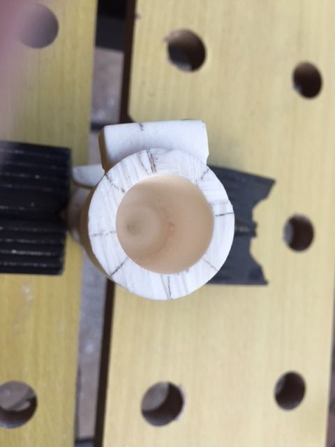
An an electric drill was then used to carefully drill out the resin lenses.
I then set up 2 drills,(I only used 2 drills just to save the time of swapping drill bits), the first with a 10mm diameter drill bit and the second with a 20mm drill bit and drilled alternately with the small drill bit and then with the larger drill bit to start to hollow out the main section of the scope. I started drilling from the end adjacent to the larger lens.
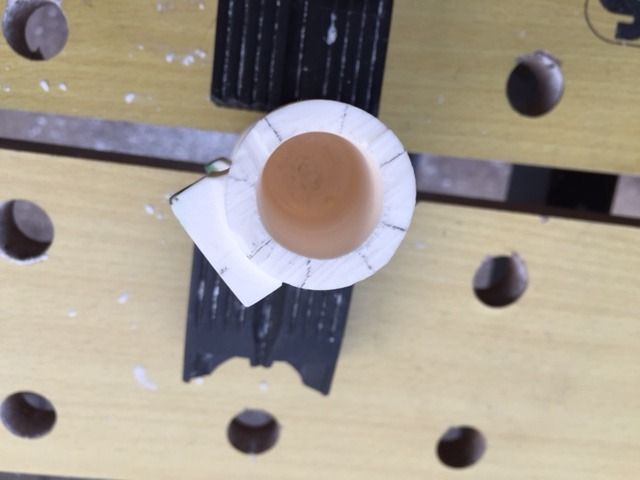
I was concious that as the scope narrows the deeper I was drilling so checked the depth of the hole that I had drilled with calliper regularly. Once I got to a depth of 46mm I replaced the 20mm drill bit with a 10mm drill bit and drilled the rest of the way through (I may open this up a little more tomorrow).
I wanted to make sure that I didn't drill through the wall of the scope by drilling too deep with the larger diameter bit (It is easier to remove more resin later if needed than repair the wall of the scope).
I still have much to do and most, if not all of what I have done here, is based on a number of other really helpful threads. In particular Squimspickle's M38 excellent scope thread provided me with the inspiration to carry out this modification.
Tomorrow however I am going to aim to carry out some further modifications that I don't think have been done before.....Hopefully I'll be successful and if not at least I have some green stuff to hand.
I must say when I first bought the DD kit I never imagined that I would be cutting and carving it up and really enjoying myself whilst doing it

-
3
-
-
Well I have now started to look at the scope and though I have quite a lot of work to do to get it completed I hope to try something a little different.
I will get some pictures posted tonight showing haw far I have managed to get.
-
Based on Scott's photographs that he kindly provided I have had a go a reproducing the rivet effect the end of the folding stock.
I took an eyelet and glued it onto a steel washer which seems to reproduce the detail pretty well and was quick and easy to do.
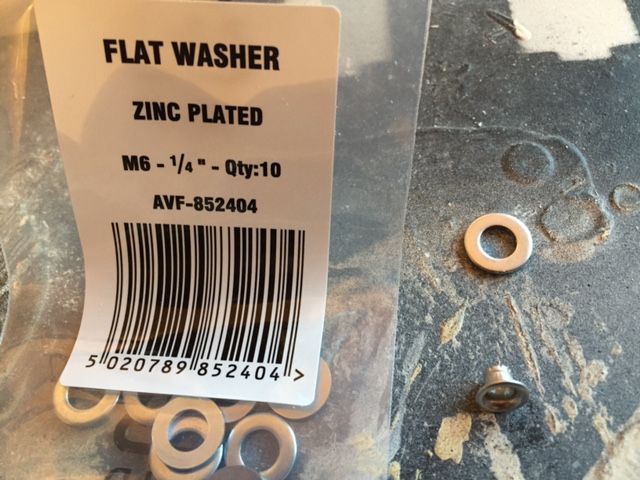
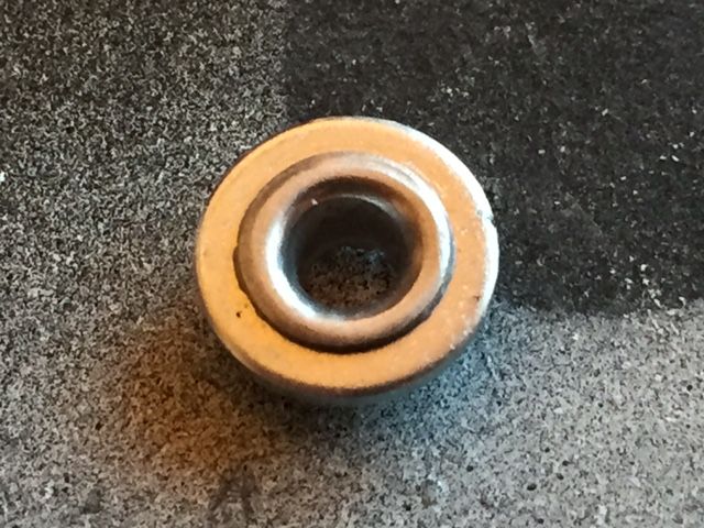
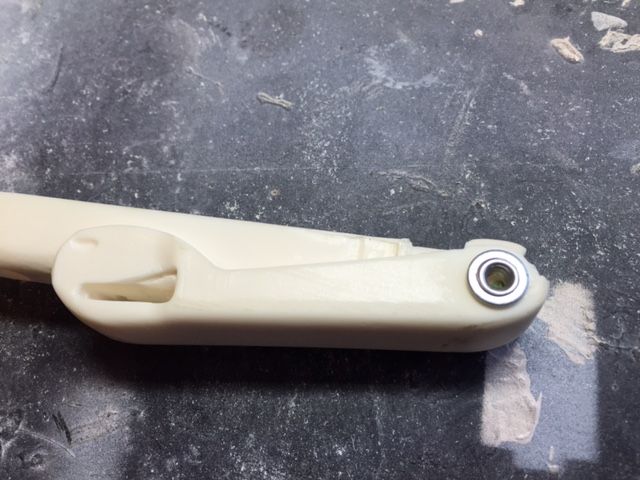
This is what it looks like in position.
-
2
-
-
Thanks Tino.
I will be using the aluminium parts from the completions set for my blaster but also wanted to experiment printing some especially with regard to the end caps.
I may print end caps and see if the look good on the ends of the aluminium parts.
-
Nice work with the new scope rail Michael.

-
1
-
-
David and Josh - Good luck with your blaster builds.
-
Wow great looking kit Richard I can't wait to see this build develop.
-
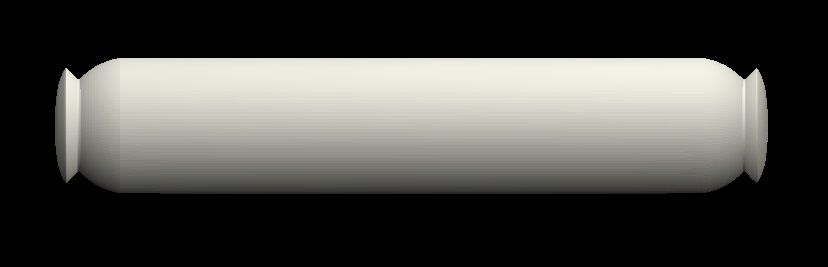
Can anyone tell me what the overall length of the fuses to the cylinders is supposed to be ?
EDIT - I may try to 3D print some to see how they come out. I have modelled them as shown in the picture below however I need to scale to the correct length.
-
That is very helpful indeed Scott.
Thanks very much for going to the trouble of taking and posting the photos.
-
@ Michael - Thank for posting the warning about the scope rail I'm sure it will help many others avoid the same issue. The blaster build is looking great by the way.
@ Chris - Thanks for posting some very very helpful photographs.
-
This is the video of the updated switch mechanism in action.
https://www.youtube.com/watch?v=91Qd9dKLicE
Scott - I agree that the eyelets look a good match for the larger 'rivet' detail and smaller detail looks like something that a small diameter tube could replicate.
-
1
-
Thrawns Guard's ANH E11 blaster build
in Build Threads Requireing Maintenance
Posted
I've not been able to do too much with the scope today as I have spayed they inside gloss black and want to make sure that the paint has properly dried before I start putting the scope back together
I also have to decide on the scope reticle I intend to use.