skyone
-
Posts
326 -
Joined
-
Last visited
Content Type
Profiles
Forums
Gallery
Articles
Everything posted by skyone
-

arduino: a cheap board for E11 blaster effects
skyone replied to skyone's topic in Electronics for Helmets / Blasters
just to let you know that this is the most updated working scheme, using 3 tiny transitors instead of led drivers and a 3.7volts lithium battery. this is the easy assembly kit and all the components needed list the most updated arduino code is here (bottom page): for more info you can reach me on facebook here -
arduino: a cheap board for E11 blaster effects
skyone replied to skyone's topic in Electronics for Helmets / Blasters
i just tested the new pcb board where i replaced the led drivers with 3 small transistors and it was working fine if there wasn't an error on the original scheme (i used a differente transistor schematic) so i have to reprint another stock -
arduino: a cheap board for E11 blaster effects
skyone replied to skyone's topic in Electronics for Helmets / Blasters
i have to finish the E11/sterling model first, to make boards 100% compatible with spaces, speakers, led and buttons -
arduino: a cheap board for E11 blaster effects
skyone replied to skyone's topic in Electronics for Helmets / Blasters
updating this project a bit, i canceled the led drivers and moved to 3 transistors + 3 resistors 1/2w to control the 3watt RGB super bright leds i will post more updates with the scheme -
Arduino Based Voice Changer
skyone replied to MissionTrooper's topic in Electronics for Helmets / Blasters
the 1 kohm resistor is needed between Arduino TX and DFPlayer RX because the serial input is goign at 3.3 volts while arduino otuput is 5 volts. " 4.1 Serial Communication Connect Module's serial port is 3.3V TTL level, so the default interface level is 3.3V. If the MCU system is 5V. It is recommended connect a 1K resistor in series" http://www.picaxe.com/docs/spe033.pdf btw great work! -
arduino: a cheap board for E11 blaster effects
skyone replied to skyone's topic in Electronics for Helmets / Blasters
just send me a PM and i will send you the link with the zip file to download (sent you) IMPORTANT NOTE ABOUT THE PROJECT: i fixed the RESISTOR value between the MP3 Player (DF Player) and Arduino, it must be 1 KOHM instead of 10KOHM or the DF player (and clones) wont work fine or at all! -
Arduino Based Voice Changer
skyone replied to MissionTrooper's topic in Electronics for Helmets / Blasters
that sounds great, i just ordered the MAX4466 over ebay i think it can go even with 3 AA alkaline batteries -
Arduino Based Voice Changer
skyone replied to MissionTrooper's topic in Electronics for Helmets / Blasters
it's working great! the MAX4466 preamp microphone is very reliable -
arduino: a cheap board for E11 blaster effects
skyone replied to skyone's topic in Electronics for Helmets / Blasters
edit -
arduino: a cheap board for E11 blaster effects
skyone replied to skyone's topic in Electronics for Helmets / Blasters
just note i made an easy assembly board to make the work easier and better. Just succesfully completed its testing, the sound is loud and clear, no clipping or noise, thanks to PCB connections. With this board it will be easier to fit arduino and their components inside the PVC pipe, saves extra cables and work, no mistakes. Size WxLxH mm main unit: 91x29x21.8 drivers module: 41.5x29x18.70 bar leds module: 35.5x19.5x9.85 -
arduino: a cheap board for E11 blaster effects
skyone replied to skyone's topic in Electronics for Helmets / Blasters
that was a good find, by the way these sounds are streamed at 22.050 kHz / 16 bit because of the limitation of their board. In this project you can play MP3 files at 44.100 kHz (and over), that is much better quality. This is because here the limit is just the SD capacity (up 32GB!). For example, you can upload the best soundtracks from the saga or any background sounds (like the stormtrooper chatting radio from 501forum), playing them while your blaster is folded. If you need the mp3 sounds just send me a pm, i will send you the link and the password. -
arduino: a cheap board for E11 blaster effects
skyone replied to skyone's topic in Electronics for Helmets / Blasters
just in case, i update the range limit of the power supply of the latest scheme with arduino pro mini, from 7,4v - 12v into 7,4v - 9v after some testing and reading around, i realized that these arduino pro mini chinese clones can't handle in this project 12 volts, it will burn their small voltage regulators. By the way, it is really unecessary 12 volts, the project just need around 7,4volts -
well done! waiting for the final
-
arduino: a cheap board for E11 blaster effects
skyone replied to skyone's topic in Electronics for Helmets / Blasters
great job! i like the idea of the transparent rod to light up the bar -
arduino: a cheap board for E11 blaster effects
skyone replied to skyone's topic in Electronics for Helmets / Blasters
love to see such works in this thread well done -
arduino: a cheap board for E11 blaster effects
skyone replied to skyone's topic in Electronics for Helmets / Blasters
you are right The voltage regulator should be positive i used the L7805CV edited first page -
arduino: a cheap board for E11 blaster effects
skyone replied to skyone's topic in Electronics for Helmets / Blasters
sure and it would be very easy it might be better to start a new code with the basic functions fire sound and led light when fire -
arduino: a cheap board for E11 blaster effects
skyone replied to skyone's topic in Electronics for Helmets / Blasters
Ops didnt know of double barrel. If they fire at the same time you might try to use 3 drivers of 700mA for both RGB Leds, the PWM control from arduino should works for both. In that case the 2 RGB leds should be connected between them in parallel to double the amperage needed. Otherwise you still need the 350mA for each color with pt4115 and pwm output. -
arduino: a cheap board for E11 blaster effects
skyone replied to skyone's topic in Electronics for Helmets / Blasters
please when you post in this topic add more specific information how to add that feature in this project, such as the updated scheme, the link of the module (datasheet), otherwise is quite unuseful. Thanks. -
arduino: a cheap board for E11 blaster effects
skyone replied to skyone's topic in Electronics for Helmets / Blasters
not sure what leds you are going to use as fire effect, are you going to use an RGB led or standards led as in the video? or you want to use 2 sets of RGB led? why should you need 2 in that case? drivers are needed in the RGB led because high amperage. In that case you need a 350mA driver for each color. But if you use standard led as the second picture (they rated about 20ma) you don-t need the driver, you can use a resistor as the blue pulse led (around 100ohm). -
arduino: a cheap board for E11 blaster effects
skyone replied to skyone's topic in Electronics for Helmets / Blasters
all the building pictures from page 2 to page 4 are now back online -
arduino: a cheap board for E11 blaster effects
skyone replied to skyone's topic in Electronics for Helmets / Blasters
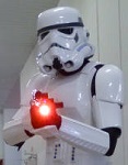
i just updated the first post image scheme, fixed a mistake in the meantime enjoy this pictures from last weekend event with arduino blaster and its powerfull 3watt RGB led! -
arduino: a cheap board for E11 blaster effects
skyone replied to skyone's topic in Electronics for Helmets / Blasters
First post main title updated: Updated scheme, link, info and code working with the new DFPlyer mp3 sound board. -
arduino: a cheap board for E11 blaster effects
skyone replied to skyone's topic in Electronics for Helmets / Blasters
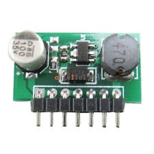
big improvements today! got the new led drivers 1watt each with PT4115 integrated circuit and they work great powering with arduino a super bight 3 watt RGB led! now it is very easy the assembly, thanks to the pins ready to solders. Moreover, i also tested a new Mp3 player board, even smaller and cheaper to the previous one. It is called DFPlayer mp3 mini (also know as Mp3-TF-16P), it communicates with arduino via serial ports, has its own library (very easy to program), it is 3watt mono (who care if it is not stereo) and we can connect to 2 speakers via the small mini amp (3w+3w). Just tested with arduino, a 8GB MiniSD card, RGB led and button and it works great! what else for just 1,20euro? you can watch both succesfull video test on my facebook page here https://www.facebook.com/fxblasterarduino/ very soon i will update the first page with everythings needed associated to this upgrade. And a new project is coming.. -
arduino: a cheap board for E11 blaster effects
skyone replied to skyone's topic in Electronics for Helmets / Blasters
i am studing a pcb board ready to assembly diy kit, in the meantime i have found another set of led driver suitable to this project it has the same PT4115 IC of the led driver linked in the first post, resistors to give 350mA 1W, but it is better because: DC 7-30V to 1.2-28V 350MA 1W http://www.ebay.com/itm/DC-7-30V-to-1-2-28V-350MA-1W-buck-step-down-module-LED-Driver-PWM-dimming-Dimmer-/201541542989 - no unecessary diods - PWM pin is ready, no need to solder wire straigh to the IC pad so, as before, we need 3 of this, one for each colured led (RGB) it is untested yet, i will order, if ok i will update the first page replacing the old one.