


Dracotrooper
-
Posts
766 -
Joined
-
Last visited
-
Days Won
5
Content Type
Profiles
Forums
Gallery
Articles
Media Demo
Posts posted by Dracotrooper
-
-
Welcome to the FISD!
-
Hi everybody,
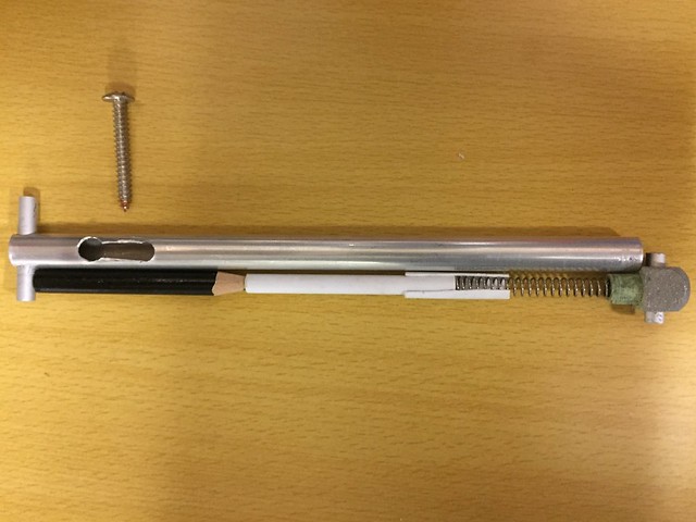
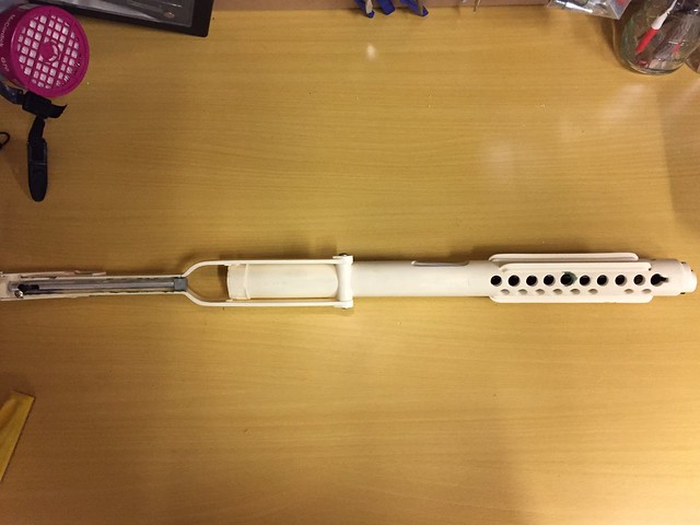
Ah, the fun continues and quite happy about some results this latest go. In this latest round, I've cut out the latch on the inner rod of the folding stock and installed the latch itself. Hinge bolts also installed; folding stock now swivels and extends to the full back position. Although not pictured, it locks into place when pushed against the end cap, which was really exciting for me to see that functionality.
I know I needed to be pretty picky about the screw used for making the latch piece. It was a screw with a width just over 4mm so there was minimal back and forth when placed through and against the vent hole notch. The screw was wood in type so that it will have maximum grab when screwed into the pencil. It's length was measured out carefully as well so that there's minimal gap between the folding stock and receiver tube.
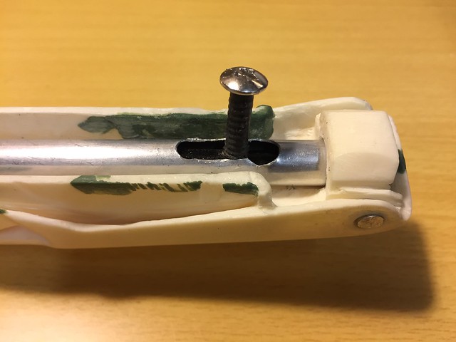
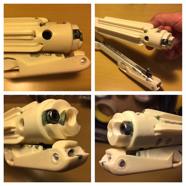
Here is a close-up of the latch cut-out. Haven't done much since the rough cut-out of it.

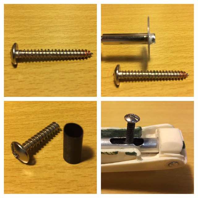
I used my Dremel with Diamond Cutter to shorten the screw. Pliers were used to hold the screw during cutting; the screw gets really hot! 5mm black heat shrink tubing placed and heated with heat gun to shrink the tubing onto the bolt thread. Latch piece screwed into pencil.
Seeing the latch piece installed was a moment of pride as I prepared a long way to get here. It is functional and able to slide up and down the inner rod =)
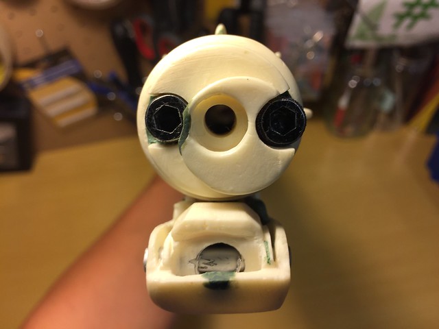
I was initially pretty confused on how to use carriage bolts for this part of the installation. The folding stock hinges installed nice and flush, with a bit of tightness when swiveling the folding stock, which I like.
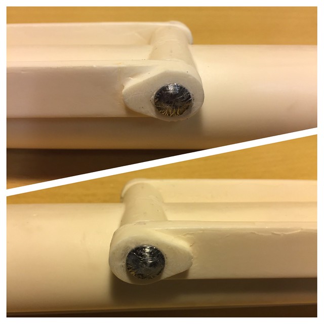
Here are some pictures of the folding stock attached.

Finally, I confirmed that my latch piece dimensions are correct as it is able to bring the folding stock fairly flush against the receiver tube with showing minimal gap.
Thanks for reading!
-
 4
4
-
-
Very impressive armor Kit - welcome to the FISD!
-
I'm doing great Jason - wish you all the best on being a member of the 501st! I'm not very knowledgeable on this, someone who is, will, and soon.
-
Welcome to the FISD!
-
Your eye for detail over your kids costumes are amazing - I foresee you suiting up to an amazing storm trooper armour in the future! Welcome to the FISD!
-
1
-
-
I usually drill a tiny pilot hole first to ensure I start dead center then I do go one bit size down from the screw diameter to drill out the hole. If it is too tight to thread you can try using the same size drill bit to shave off a bit more on the sides of the hole. Sometimes I end up going to the next bit size up and it still leaves enough resin to thread into. If that takes off too much, green stuff or hobby epoxy will help to seal it up and re-drill to a better fitting.
Right right, tiny pilot hole ensures for precision and one drill bit size down for pilot hole that's counter sunk a bit with bolt diameter to allow for easier grab contact when bolt is manually screwed in. I can see, that it is here, effort can be made to make sure bolt is coming in perpendicular with the piece. As it turned out, I blundered my pilot hole and waiting for green stuff to cure to have a second go.Also I have been testing the use of Blu tac as a non permanent way to keep things in place but allow parts to move without having to commit to glues. For my F-11D stock handle, I used aluminum tubing as a port to insert the screws into. I stuffed the tube with blue tac, screw the bolts into the tubing and they stay in place , allowing the stock handle to move.
Interesting results you've come away with in using Blu tac, glad that's working for you. Will need to explore this method for myself if I have the need. Thanks Brian for your help. -
As I'm relatively new to hobby building...I have a question about screw installation. With my coach bolts measuring a width of 5 / 32 " including the thread, do I simply go one step down to 9 / 64 " to create the pilot hole? Following, in going about to manually screw the coach bolt, would I then have the thread groves for a nice snug fit? This makes sense to me but I want to know if this is common practice or perhaps there's another method.

-
Welcome to the FISD!
-
Assuming you only apply glue to the barrel/stock mount, NOT the folding stock itself, I'd assume you'd still have full motion. :-)
Ah of course! Thanks for clearing that up for me Dan
-
1
-
-
Hi Jesse, Not saying its the right way to do it, but, I just made the hole in the folding stock large enough to take the square. As coach bolts usually have a nut at the back, which can't really be done here, I'll be gluing the coach bolt thread into the body (when I'm happy with where everything sits etc). :-)
Thanks Dan - I understand more of the mechanics involved in using this kind of screw, very helpful. As I am creating a folding stock that can lock and unlock at the latch, I am wondering if applying CA glue at this hinge part would inhibit this functionality...I made the hole large enough to be snug on the square and thread. For a long time they were held in with friction! Though after a few times apart this was no longer good enough so I added a drop of CA glue.
Interesting testimonial Chris, with the friction giving way, you need to apply CA glue anyway. If I need to apply CA glue, how to still enable swivelling of my folding stock? I am still rather confused... -
Hi all,
I'm unclear as to how to install the bolts that hold the folding stock fork ends to the rear-under side of the receiver tube. The bolts from the completion set are domed with a square part directly under this domed bolt head. The bolt including thread measures 5 / 32 inches. How do I turn the screw and what pilot hole size is best to ensure a snug fit? What to do with the square base directly under the domed bolt head? I did a crude attempt that was strenuous and caused loud squeak sounds!


-
I learned this past year, everyone is on their personal build journey, you'll get there future trooper!
-
oooh, your blaster is looking more fine as each day progresses Dan! I like your measure twice, cut once approach. It's unfortunate about the trigger guard mishap but you still have plenty of aluminum for a second go. I will also need to study Chris's documentation on how he successfully bend aluminum.
-
1
-
-
Hi all,
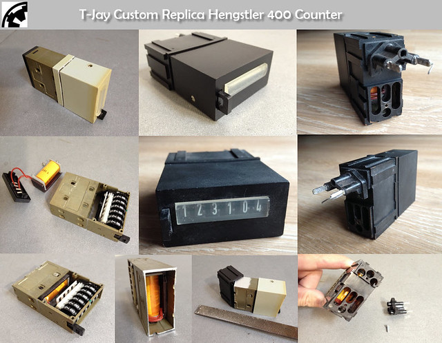
I recently acquired a very interesting piece for my E-11 Blaster and excited to share! I have a replica Hengstler 400 Counter created by Tino himself. I just so happen to inquire about his counters after placing my completion set order as he had a limited run back on 2015 for conversion counters. I was delighted to hear he was about to do a limited run of complete counters and that I was first in line for one of these. As it turns out, he is not offering a run of these any longer so I have the one and only unique piece! I'm feeling pretty special about now.
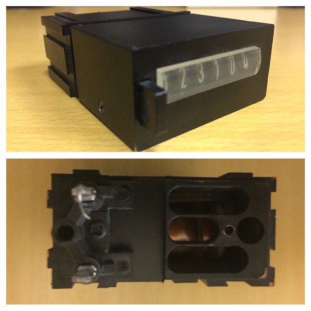

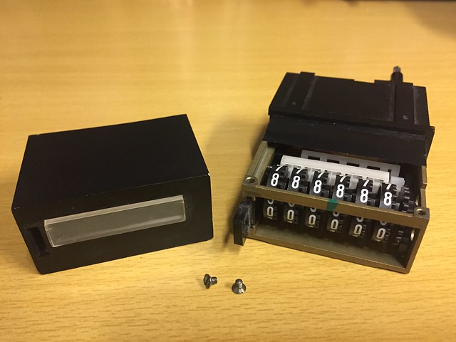
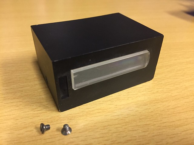
This replica Hengstler 400 Counter is a complete piece, fitted with an original Hengstler socket, and maintains the exact dimensions of the original counters. Tino masterfully shortens the metal housing and plastic cover to correct Hengstler size. Sorry Eagle enthusiasts, no big or small logo on this type of counter =) Without the two screws and boarder as well.
Furthermore, this type of counter came with a D-shaped window for the plastic case side of the counter. The curvature is nice and I appreciate this detail. I agree with Tino that this stylized window exceeds the flat window on the original counters.
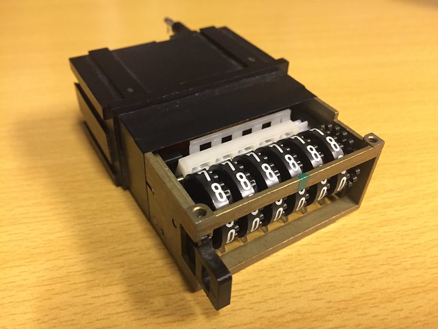
The reset button for the number rolls is operational and numbers can be reset to zero with a push of this button. Number rolls are set manually by finger. Number rolls are each in black with all lettering in white, which is screen accurate.
A really interesting feature that adds to the realism of the piece is the preservation of the coil; it can be seen inside the black plastic socket through the slots. The coil also adds believable weight to the counter. Adding further to the realism is Tino's added touch of including soldering and a short wire to the connector pins. I also asked Tino to age the counter and he's done a stand-up job.
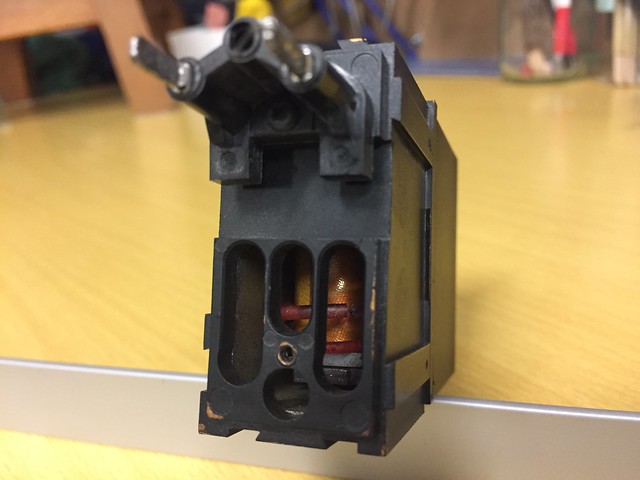
Tino with his fine craftsmanship, impressive indeed - I am fortunate to own this unique piece.
-
1
-
-
Wish you all the best James in getting EIB status. You look absolutely lethal by the way! A TK with administration rights can move your post to here I believe - Request Expert Infantryman Status
-
Welcome to the FISD! You are taken care of here!
-
8 minutes ago, CableGuy said:
Cheers Jesse. I appreciate the feedback and advice. :-) I'm currently in the "trial fitting" stage. I think I'm likely to glue quite near the end, once I know where and how everything fits together. Also, painting might be easier with separate parts - for metallic and plastic appearance. And yes - I'm really enjoying it!! Just need more hours in the day. ;-) Sent from my iPhone using Tapatalk
Ahh dude
 that's exactly my approach as well - so funny our approaches are similar: pursue excellence with component pieces. I think I have similar blood to your part of the world as I align myself with Tino's build approach as well lol
-
1
-
-
Nice work Dan - your blaster is really taking shape now. Not sure what stage these photos are on your build but applying CA glue to go along with the bolts may go along way to ensure the grip piece remains attached to the receiver tube. I remember Tino saying somewhere that the glue provided in his completion set is good for resin to resin contact. =), my two cents, hope you're having as much fun as we the audience!
-
1
-
-
Welcome to the FISD Albert! Nice video =)
-
Looking good, ready for battle! congratulations and welcome!
-
2 minutes ago, CableGuy said:
Excellent find, Jesse. I have some aluminium, (approx 2mm thick), that came with Tino's kit that might do the job. It was intended for the scope rail but I ordered a pre-built rail as well, so this is going spare. I think that should be okay. I've not really worked with metal in this was before. Any tips for cutting? Hacksaw? Not sure how straight or tidy the edge would be with a hacksaw?
Funny you should relay this - I too have this spare aluminum part as I opted for the upcharge to get the finished scope rail with Tino's Completion set. Good to know it measures 2mm in thickness. Warning! Aluminum gets really hot, really fast! I found out the hard way when I initially attempted to cut to various sizes, the 5mm aluminum rod provided in the kit. The trigger guard is a much larger piece of aluminum and you want straight edges too, let alone a curved surface! I am thinking commissioning a fabricator to get it done for a few bucks is the safest way to go, and it also ensures for a quality piece. Yeah, I'm without the proper tools. Perhaps a solution can be suggested here...
-
Let's get some traction on this together shall we?
I've come across a posting by Lucas (ZeroRoom) back in 2011 with topic 'The Best Sterling Templates EVER!' I downloaded the PDF on the trigger group:

The length of the trigger guard, laid out and flat is 105mm long and discussions say the width is between 11 and 13mm. Perhaps we can gauge a workable width by measuring the width of our Doopydoos 'ports' (for lack of a better word), that take in the trigger guard ends?
Discussions say dimensions are not off of a British Sterling, but I gather the measurements are still suitable.
-
2
-
-
3 hours ago, T-Jay said:
Very cool progress, Jesse. Loving how familiar some of your pictures look to me
 Thanks for the kudos. Happy to help.
Locking forward to your folding stock locking mechanism...
Tino, you're the man

-
1
-

Noobie signing in
in New Member Introductions Archive
Posted
Great to have you join us, welcome to the FISD!