

ireachy
-
Posts
50 -
Joined
-
Last visited
Content Type
Profiles
Forums
Gallery
Articles
Everything posted by ireachy
-
The belt is one of the most complex parts of the R1 TK armour. Not only does it have projections that key it to the ab plate - as per Jimmiroquai's posts - but it also has that difficult two-part construction, with the overlaps at the sides. In some pics from the SWCE display the back part of the belt even angles up slightly to the det pack attachment area. It is also probably worth looking at the shoretrooper belt and compare the way that the belt boxes (on the actual belt itself) are constructed. I also think that the hanging belt boxes attach to the belt in a similar way as the shoretrooper ones do. They attach 'into' the belt box detail above them.
-
Will pluck up the courage soon for the tube stripe cut away. Superglue gel is a useful tip thanks. I'll stream through plenty of ref material before I tackle the jaw seamline. Thanks for the pointers. If any help then here's a link to the pics I took at Celebration Europe last year. There are many tighter / better pics out there than these, but I did try and get some unusual angles for a few of the shots. Feel free to use if you'd like. http://s1146.photobucket.com/user/Ian_Reach/library/SWCE%20-%20RO%20-%20Stormtrooper?sort=3&page=1 ireachy
-
Par_, I followed your method regarding use of black electrical tape for the brow. If you pull / stretch the tape as you lay it down along the brow it tends to stick better and conform to the curve. I applied a single strip of the tape aligned with the top front edge and then tucked the reminder along the underside of the brow - the part that is white and inaccurate on the BS helmet. Using the rounded end of a wooden coffee stirrer I then pressed along the under edge to make sure the tape adhered fully. Some of the tape ran over onto the faceplate under the brow. I also pressed this into place. I then used a scalpel blade and cut the excess tape from the faceplate, aligning the blade along the underneath edge of the brow. Using fine pointed tweezers I then removed the excess tape very carefully. Finally, I noticed that I has two very small air bubbles on the front of the brow. Using the scalpel blade I punctured a very tiny hole in the bubble and then smoothed away the bubble. Worked a charm. I haven't added any tape to the upper surface of the brow. The taught electrical tape has blended perfectly with the helmet's original rubber plastic and you cannot see any seam.
-
Par_, good to see the neck trim trick. I have looked at using some OT S-shaped trim but it looks a tad too bulky, so will have a play with your weather excluder idea. Also have some excess trim from X-wing helmet so that may be a go-er too. The cheek tubes are looking great. That is the part that I am likely going to leave to last as it scares the heck out of me - too much opportunity for a catastrophic slip with the Dremel!!! Good spot on recreating the nose / jaw separation line. Something that I will now look to do on mine. I may post some WiP pics of my lid here, but don't want to clutter your build thread. Best, ireachy
-
 Great work sir - as ever. As you and others have said the detail is in the amount of weathering, and having the restraint to dial it back a tad to reflect the SWCE 2016 buckets. Just under a month and I get to see this helmet in person. Can't wait to get my grubby mitts on it and have a real close-up look at your skills. Fab. Next will be the armour!
 -
Hi Riva, just an obs, but the frown mesh - as seen on the helmets at Celebration Europe 2016 - is aligned vertical / horizontal, and not on the diagonal. A very small detail, but easy to mod to get screen accurate if that is your intention. Will enjoy watching your thread as in the process of modding my BS helmet too. Great to see how folks are tackling the mods and tweaks. Keep it coming... ireachy
-
ScouseTrooper, that image is actually concept art for the film - it is not from the film itself. It can be seen in the 'Art of Rogue One' book - although interestingly the image in the book is horizontally flipped - you can tell as the Type 4 pack is a mirror image of the one seen in the trailer long shot and on the Hot Toys etc. ireachy
-
Rogue One Stormtrooper Back Pack part found
ireachy replied to Sly11's topic in Build Threads Requireing Maintenance
Marv, check the R1 back pack build thread in the R1 part of this site. There is an entire section in there about the correct A.L.I.C.E. pack to use and way of distinguishing between medium and large pack - incl. pics for comparison. Aside from the size difference between the centre pocket and the two outer pockets - as per Bulldog's comment above - the easiest way is to look at the number of webbing details on the side of the pack. The medium pack does not have a bottom single webbing patch Whereas the large pack - the one used on the prop seen at Celebration Europe 2016 - does have the extra bottom single webbing patch Hope this helps. ireachy -
Par_, I think that whilst the R1 TK helmet had the mesh under the grill, I am sure that the attached reference shows that it was not 'backed' i.e. there is just the mesh in place. You can see the light or white of the helmet inside showing through. The fantastic hi res image is available here: https://c1.staticflickr.com/9/8604/28089834910_019dda3a55_o.jpg I also believe that the image shows that there is a black tram line running around the cheek and brow rhomboid. But, there is no doubt that these also have a greater 3D 'pop' than is present on the BS helmet. Hope that this is helpful. ireachy
-
Rogue One Stormtrooper Back Pack part found
ireachy replied to Sly11's topic in Build Threads Requireing Maintenance
Sithpiper, when pulling over and down the A.L.I.C.E. pack flap over the centre pocket make sure that you tuck in and under the sides (of the flap) so that the edge aligns with the two webbing guides (on the flap). The total area / width of the flap shouldn't show. In effect the flap is layed out so that the webbing guides align with the edges of the stuffed centre pocket. That will help give the CE shape. When you come to using the polyprop webbing and slider buckles to tie-down down the flap, and also attach A.L.I.C.E. pack to the frame, they should fall / align into the gap between the centre pocket outer edges and the inner edges of the other two pockets. The polyprop webbing actually runs down through and then back up the webbing guides on the flap. When tensioned this also helps give the CE shape to the pack. Also remember to add some stuffing onto the top of the centre pocket - before - pulling over the flap. On the CE pack there is a slight 'hump' to the flap as it pulls down over the centre pocket - ireachy -
Keep it coming - looking to mod my BS now that I have the Jedha pack sorted. Really interested to see what you are looking at regarding replacing the rubber seal / trim for the bottom edge - but waiting patiently so don't let me derail your build :-)
-
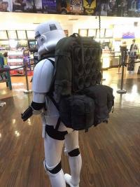
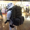
Pic of mr paul's and my packs side-by-side before the midnight launch troop. Both built separately by us and the first time they had been in the same place. Came out fairly close, and we're both happy with the results. Thanks to all on the forum for prompts, questions, demos, input, observations etc. Best, ireachy
-
Great to see so many Jedha patrol troopers with packs. Fab work guys
-
Sithpiper, is that silicon tubing or surgical tubing? I've managed to get 6mm OD / 4mm ID silicone tubing through fairly easy. I did thread up from 3rd to 4th then up to the top eye. Then took the lower part of the tubing and added the wraps 3rd eye down to 2nd eye, then through 1st eye and out with no problem. Just cut point to the end of the tubing to assist the threading through - as illustrated by mr paul above. The silicone tubing has enough stretch in it to help pull through the small diam. top 3 eyes. As mr paul indicates this is achievable with either silicone tubing or the surgical tubing. The key is slow and even pulling whilst holding the eye very firmly between thumb and forefinger - i actually bruised inside of my thumb nail as I locked the eyes in tight under my thumb nail. But that technique meant that I reduced the risk of the eye snapping. Have you managed to get the whole rod threaded with tubing now? ireachy
-
Phillthy, great to see the post of your pack. Been great to see you develop the build from v1.0 to your v2.0. The change in the overall look of the pack is fab. Also, great tip regarding the use of the textured paint and your application tip. The final component of the prop - the canvass roll, webbing, and buckles, plus mr paul's weathering - will be posted imminently. Hoping that others will start to post up their packs as we approach the premiere. ireachy
-
Ammo Box Possibly the first component of the CE back pack found part to be positively identified was the 'ammo box'. It was the component on the prop at CE that made me think "I want to build this. How hard can it be? They've used a horticultural flower pot packer as part of that pack!" Hopefully our more in-depth investigations of the CE pack make amends for my first tentative part identification! As we are aware the ammo box component is actually a Norwegian (NATO) grenade box - M4704-101113. The grenade box consists of two identical halves with two snap on carry handles on one half of the box at either end, and two hinge flaps which are identical, allowing the box to hinge open and also tension snap closed. Most boxes also have a plethora of stickers on them with military ID nos. and warnings regarding explosives. The inside of one half of the box also has a snap on tray with 'cups' to retain the grenades in place. The half with the grenade cup tray in place also has a rubber grommet seal that runs around the periphery of the box half to ensure a watertight closure. The grenade cup tray can be snapped into either half of the box i.e. in true military efficiency all parts of the ammo box are replicated and the various peripheral components can be attached to either of the box halves - which are the same cast piece. The ridges on the outside face of each box also allow a non-slip stacking capability - but that is beyond our requirements for the CE prop replica. The CE pack uses one half of the ammo box without any of the handles or latches. The two handles are easily popped off if you decide to use that half of the box. The hinge / closure latch - there are two of these - also pop off with a little pressure. It is assumed that the various stickers were also removed for the prop. As can be seen in the picture above and below, the rubber grommet seal was also removed for the CE prop. The CE prop uses just one half of the ammo box with all the peripheral pieces removed, except for the grenade cup tray. However, reference shows that the cup tray was removed and a piece of black dyed fabric inserted to baffle / hide the inside of the box half, and maybe provide some added depth / texture for filming. Analyses of reference material has not provided any detailed identification of definitive material used for the black dyed cloth used. Members of the team have used heavy weave cotton or callico and then dyed this material black. Mr paul will detail the installation of the cloth part. The grenade cup tray is simply snapped back into place over the material part. There has been some discussion about the colour of the ammo box on the CE prop, with many reproductions tending for a black spray paint application before weathering. However, as evident in the picture above, we believe that the majority of the ammo box was actually left as found part, with no paint application to the sides of the box. Zooming in on the excellent reference above shows that certainly the interior of the box was left as found - pic below. The outward facing part of the ammo box and grenade cup tray do indicate that the plasticky green colour of the found part may have been knocked back with Olive Drab paint - or some similar colour - and with weathering. The pic below highlights where chipping of paint applications appears to be present and the found part original plastic shows through. An excellent reference for those looking to try and replicate the CE prop in exact detail! It is also clear that a random light spray of matt black has also been applied to small areas of the box lip and parts of the grenade cup tray, although these are generally 'restrained' in their application. The outward facing part is most definitely not a uniform black. Weathering splatters and dusting have been liberally applied. Mr paul will cover how he painted and weathered his version 2.0 pack. The images below show some of mr paul's and my thoughts and investigations we did regarding the application of black paint to the ammo box prop - a haphazard eye into our musings and thoughts as we looked at this component of the CE pack - sorry! As a point to note, we have not glued any of the grenade cups into place on any of our pack builds - they have some back and forwards play and rotate through 360 degrees. However, again, if one is looking for a perfect CE prop replica then the reference here should enable you to judge the rotated position of each grenade cup and you can glue them in the correct position / orientation. One important point - the grenade cup tray has a distinguishing mark on it - a circle with internal outward pointing arrow. On the CE prop the grenade cup tray is snapped onto the ammox box with this distinctive mark located at the bottom centre. Suppliers There are numerous suppliers of the Norwegian grenade box in both Europe and the U.S., although experience showed that initially for the U.K. it proved cheaper to import in from Germany, than buy within The Realm. Germany still appears to be a stronghold for consistent supply for Europe. An on-line search for 'Norwegian grenade box' turns these up from several army surplus suppliers. Avoid searching 'Star Wars ammo box' or 'rogue one ammo box' on Fleabay as you will be 'scalped' wrt cost. We recently saw one go for >£100, and yet they can be sourced for around £30-£40 + postage in U.K. / from Germany. Mr paul will post build titorial, including painting and weathering details, following this post. Important point: the team has been unable to track down any reference for the back of the ammo box prop and so all the points about colouration are made with that caveat. Further, as there is no reference for the back of the ammo box on the CE prop then the team have no definitive answer regarding attachment of the box to the frame. Mr paul will detail how he has attached his ammo box, building upon experience from his version 1.0 and 2.0 builds. Canvas roll, webbing and cam buckles to follow very soon. Then the final instalment will be weathering and overall tweaks to get the 'CE look'. Only three weeks and we get to see these on the screen, and then I expect tons of observations, especially when more reference material is released. Best, ireachy
-
Thanks SlyFox, yes, using your analysis of the angle brace we are now confident the M75 is the correct frame. Maybe I should have gone back and edited the original post as I have been those analyses as a definitive when talking with other folks. Fab investigative work here, loving it... ireachy
-
ALICE pack shoulder straps As has been discussed on various forums and threads such as the Rogue One Back Pack Found Part thread here on FISD, we know that the shoulder straps used on the CE prop are ALICE pack shoulder straps. There are two types of shoulder straps available with the ALICE LC-1 or LC-2 frame, the most common type have padding that extends approx. 2/3 the length of the strap. These are not the ones used on the CE prop. This pic shows the inaccurate but more common ALICE shoulder straps. The shoulder straps used on the CE prop have padding extending the full length of the wide component of the strap and are specifically known as the 'woodland camo shoulder straps'. Experience is showing that many ALICE large packs with frames are being shipped from army surplus stores with the inaccurate shorter padded shoulder straps. It appears a bit of a lottery if you receive a pack with the accurate woodland camo straps. Sourcing from private sellers can guarantee the woodland camo straps where these are shown in pics. It is possible to PM many surplus sellers and check / request supply with the woodland camo straps. The correct straps can also be bought separately, but at least in the UK these are nearly as expensive to buy as the whole ALICE pack and frame combo. So just a word of caution. As you will have seen in mr paul's post regarding dyeing the ALICE pack, the shoulder straps are removed from the frame and dyed at the same time, and in the same way, as the rest of the soft pack. Deviations from standard use and attachment of ALICE shoulder straps to the M75 frame Myself and mr paul have noted some significant variations in the way that the ALICE shoulder straps, when compared to how they are traditionally configured and attached to the ALICE LC-1 or LC-2 frame. We do not think that these facts have been noticed before. These are: The left and right shoulder straps are swapped / switched so that the ALICE left strap becomes the right CE shoulder strap, and the ALICE right strap becomes the left CE shoulder strap; The ALICE buckle used with the tensioning webbing - that runs from the top of the shouder pad and attaches the shoulder strap to the M75 frame - have been reversed / flipped upside down from the standard ALICE configuration; and A slider buckle - the same antique brass slider buckle as used on the front of the CE ALICE pack and at the base - is used to tension the top shoulder webbing to and around the M75 frame horizontal bar. We'll look at each of these points. Shoulder strap switch-over On a standard ALICE pack configuration using the woodland camo straps, the left and right straps are attached as in the pics below, with the cant / bent of the straps flaring to the outside: We know this is the case as you can see the 'V-line' of stitching at the pad bend faces outwards '<' However, on the CE prop the 'V-line' of stitching at the pad bend faces inwards '>', and thus so does the pad bend. This is a significant change to the ALICE pack set-up as deployed, and how you will receive your shoulder straps attached to the ALICE LC-1 or LC-2 frame. Inversion of the ALICE buckle on top of the shoulder padding CE prop reference pictures show that the Alice buckle on top of the shoulder pad, which tensions the shoulder strap to and around the frame horizontal bar, has been inverted compared to standard ALICE strap deployment. In the standard ALICE configuration the ALICE buckle tensions so that it lays flat. However, on the CE prop the ALICE buckle is inverted / turned upside down. In the pics below you can see how the end lip of the ALICE buckle is pitched upwards, rather than laying flat to the should pad. You can also see the curve of the buckle side profile and how this is upside down. Fortunately the right shoulder strap is placed over the pauldron on the CE display and reference shows that the ALICE buckle inversion is present on both shoulder straps. Use of slider buckle to tension the shoulder top webbing and attachment to M75 frame The final variation to the standard, as deployed, ALICE pack shoulder strap configuration concerns the use of a antique brass coloured slider buckle to tension the webbing coming from the top of the shoulder strap and 'lock' the webbing around the M75 frame horizontal bar. We believe that the unorthodox way that the ALICE buckle has been inverted requires the slider buckle to provide extra tension on the webbing - the webbing that leaves the shoulder pad and wraps around the M75 frame horizontal. Without the tension provided by the slider buckle on the webbing at the point where it wraps around the frame, the weight of the frame and pack pulls the inverted ALICE buckle, on the top of the shoulder pad, up and backwards - see pic below for example of inverted ALICE buckle configuration but before we discovered the slider buckle at the frame and the tension it provides. Hopefully these reveals in the nuances of the CE pack prop shoulders is interesting. Mr paul will next run through the attachment of the shoulder straps to the M75 frame showing the CE correct webbing threads through the slider buckle and inverted ALICE buckle. He will also detail the painting of the orange patch / flash present on the left shoulder pad (which is actually the ALICE right hand pad as per standard ALICE pack deployment!). Best, ireachy
-
ALICE pack webbing and buckles The ALICE buckles at the bottom of the pack - used to attach the soft pack to the frame are removed and replaced with ladder / triglide / slider buckles (henceforth referred to as slider buckles). The ALICE pack webbing that wraps over the top of the soft pack and holds down the pack flap over the central external pocket are cut off and replaced with 25mm / 1" polyprop black webbing. Slider buckles - 2 for each webbing strap on either side of the external central pocket, so 4 in total - are also used. SlyFox provides an excellent overview of this webbing on the Rogue One pack found parts thread on this site. Ignore the text in the image below - that was part of mr paul and myself working out slider buckle positioning which mr paul will discuss in the next instalment. The slider buckles appear to be antique brass - see pic above and below. Ignore the arrows in second pic below - again these are part of mr paul and myself working out slider buckle positioning and webbing threading which mr paul will discuss in the next instalment. The first pic also shows that a slight 'lip' to the slider buckle is evident. The dimensions of the slider buckles can be seen in the pic below. 30mm external width / 25mm internal width. So in total for the ALICE soft pack component of the CE pack you will need 6 antique brass slider buckles 30mm external width / 25mm internal width. Note that 2 more of the same slider buckles are used on the shoulder straps to attach the straps to the M75 frame - we will detail this following mr paul's pack build. I am mentioning this here so that you purchase atleast 8 slider buckles. 2m of the black polyprop 25mm / 1" webbing should suffice for the ALICE pack webbing. Note that when replacing the bottom ALICE buckles with the slider buckles, the CE prop re-uses the original ALICE pack webbing for these attachments - DO NOT cut off that webbing, although the webbing that attaches the actual slider buckle to the base of the pack appears to be the black polyprop 25mm webbing. The original ALICE webbing is used to loop around the frame and pass through the slider buckle, attaching the pack to the frame base. Mr paul will detail these points. As discussed on this thread it appears that the bottom slider buckles may be painted black. The other 4 slider buckles used with the black polyprop webbing are left as antique brass. Suppliers The black polyprop 25mm / 1" webbing is relatively ubiquitous and readily available from numerous retailers and online suppliers. The team purchased their antique brass slider buckles - 30mm external width / 25mm internal width - from the following site. It is worth noting that supplies have been cahllenging in the last month or so. It is possible that silver nickel or gunmetal buckles can be weathered using washes and vinegar corrosion techniques to achieve the correct tarnished finish (thanks for the pointer Fett4Real). http://www.ebay.co.uk/itm/181396564350?_trksid=p2055119.m1438.l2649&var=480379766443&ssPageName=STRK%3AMEBIDX%3AIT Mr paul will next detail the adjustments and mods to the ALICE soft pack and packing and folding to achieve the CE prop look. Following that we will detail the shoulder straps including painting of the orange patch / flash. Best, ireachy
-
Also, as an addition, any folks that are at a point where you are adding the orange shoulder strap patch / flash to the left shoulder strap, hold off as we have some observations that will affect how that detail is applied to the prop - hopefully to be detailed by the end of this week - pending tad more investigation we're doing. One month to go 'til premiere and general release - of the movie that is - not reveal wrt shoulder strap... ireachy
-
Just as a thought - wrt reflectivity of the silicone tubing - one mustn't discount the effects of weathering to 'dull' the potential glossiness of the silicone tubing. The rod that underlies the cable also shows the same weathering effects as the cable / tube itself. But as previously stated, the surgical tubing posited by SlyFox is very intriguing. ireachy
-
Bulldog44, we are going to look at SlyFox's pointers as they are compelling. Part of the point of posting the build thread is to look at investigations from others, so that we can all benefit from an open forum and discussion. The beauty of these types of fora The flat black look of the surgical tubing is very intriguing. That resonance with regard to reflectivity, dull and flat colour is important, along with the shaping of the wraps - importantly retention of the slight convex profile - certainly not flattening, tending to concave, the spacing of the wraps and thus the OD of the tubing, and the ability to feed through the rod eyes, and the correct 'pinch'. All great, and the critique, comments are so welcome. The canvas roll will be a case in point! Definitive ID of that roll is elusive at this point - although we do have some 'close' candidates. ireachy
-
ALICE pack I am not going into exhaustive detail regarding the ALICE pack as it has already been confirmed as a found part, indeed it was one of the first parts of the CE pack to be verified. However, there has been some discussion regarding the size of ALICE pack used so there is value in looking at the evidence base for the Large ALICE pack and also points regarding the LC-1 and LC-2 designations, and what, if any bearing these have on the prop. The A.L.I.C.E. system was developed by the U.S. Army during the late 1960s and early 1970s as the standard load carrying system for infantry of that era - All-Purpose Lightweight Individual Carrying Equipment - A.L.I.C.E. It replaced the M-1956 Load-Carrying Equipment (LCE) and M-1967 Modernized Load-Carrying Equipment (MLCE) in 1973. There are 2 components to the system: the fighting load system; and the existence load system. The fighting load was based around a webbing belt and suspenders and designed to be carried by infantry into combat, and at all times. The existence load system was supplementary to the fighting load and was designed to carry additional equipment that a soldier would require i.e. consists of items other than those in the individual fighting load which are required to sustain or protect the infantry rifleman, which may be necessary for the infantry rifleman's increased personal and environmental protection, and which the infantry rifleman normally would not carry. When possible, the individual existence load items are transported by means other than man-carry. Otherwise both the fighting and existence loads are carried by the infantry rifleman. Individual existence load items are usually carried in the field pack (Wikiepedia, 2016). The medium and large field packs are part of the existence load system. Again from Wikiepedia (2016): Field Pack (medium) - The field pack is made of water repellent treated nylon duck and webbing, spacer fabric, and metal hardware. It can be used with or without the LC-1 Field Pack Frame. The main compartment closes by means of a drawstring secured by a plastic cord clamp. A radio pocket is located against the back on the inside. The size of the pack may be decreased for smaller loads by means of three para-cord ties, stitched to the inside bottom of the pack, and three metal D-rings located directly below the internal radio pocket. Three pockets on the outside, with strap and buckle adjustable closures and with snap fasteners for quick access, are provided for miscellaneous items. The top flap has a pocket with a hook and pile fastener tape sealed closure. Equipment hangers are located above each outside pocket and on each side. Drainage eyelets are provided in the bottom of the main compartment and the outside pockets. An envelope pocket is located at the top, back of the pack and padded with spacer cloth, into which the field pack frame is inserted when the field pack is used on the field pack frame. Buckles and straps at each side near the bottom are used for anchoring the field pack to the field pack frame. Two rectangular wire loops located at the top back of the field pack and D rings on each side at the bottom of the field pack are used to provide shoulder strap attachment when the field pack is carried without the field pack frame. A waterproof bag is supplied for the main compartment and each of the three outside pockets for keeping equipment dry. Field Pack (large) - The construction and materials in the large field pack are similar to the medium field pack with the differences being: it is much larger in size; the center outside pocket is larger than the other two main outside pockets; and the addition of three small outside pockets above the larger pockets. The large field pack MUST be used with the LC-1 Field Pack Frame. LC = load carrying. The large field pack has to be carried with the LC-1 or LC-2 frame. The medium did not, although was often used with the frame. The original 1973 fittings for the system were designated LC-1, however in 1977 parts of the system were re-issued with more robust fittings due to failures in the field. These upgraded components were designated LC-2. The main differences for the field packs were: Field Pack, LC-2 medium (NSN 8465-01-019-9102) with new buckles and no liners Field Pack, LC-2 large (NSN 8465-01-019-9103) with new buckles and no liners Frame, Field Pack, LC-2 (NSN 8465-01-073-8326) green aluminium Following pics are the Large pack Diagnostic features of the CE ALICE pack We know that the ALICE frame was discarded / not used as part of the CE prop. The frame as been discussed in this build thread already and is confirmed as the M75 pack frame. Therefore it does not matter whether an LC-1 or LC-2 frame is purchased as this will be discarded during the build. As we know for the CE pack, the ALICE pack shows a larger external central pocket than the twp side pockets. This can be discerned even though the closure flap for the pack is folded down across the central pocket. In addition the key diagnostic feature relates to the webbing mounted on the external sides of the pack. On the medium pack there is two part webbing patch on the upper part of the side wall and then another patch two-thirds of the way up from the bottom of the side wall. On the large patch theses webbing patches are present in the same locations as the medium pack, however there is an additional double patch of webbing located one-third of the way up from the bottom of the side wall. This double patch of webbing is present on the CE prop e.g. definitive ID that the large ALICE pack was used for the prop. The difficult question is around whether an LC-1 or LC-2 large pack was used. As far as we have been able to ascertain there does not appear to be any external cosmetic difference between the LC-1 and LC-2 versions of the large pack. So long as the pack has the standard ALICE buckles then you are good to go. The internal liners are not used as part of the CE prop so will be discarded if you have an LC-1 pack, and will not be missed if you have an LC-2 pack. The critical point is that the ALICE buckles on the webbing must be present. Colour There has been debate about the colour of the ALICE pack used on the CE prop. Is it one of the scarce black ALICE packs, or is a painted / dyed common olive drab pack. Analysis of the numerous reference pictures, both under the convention centre's lighting and from flash photography, makes us believe that an OD pack was used and then dyed black. This is further corroborated by the team dyeing packs and comparing with the reference material. Further this would make more sense as the OD packs are readily available compared with the black version. The 'tell' is associated with the ALICE pack webbing which does not take / hold the black dye as well as the main body of the pack. This 'tell' is present on several of the original ALICE webbing straps retained on the CE pack. Suppliers The large ALICE pack OD is relatively easy to locate in the U.S.A., a little more scarce in Europe, U.K. and in other parts of the World, but still reasonably easy to acquire. The usual army surplus suppliers appear to have them in stock.\ Go-Army on Fleabay UK http://www.epicmilitaria.com/us-army-alice-pack-large-lc-1.html https://colemans.com/shop/pouches-bags/alice-pack-lc-ii-large-u-s-g-i/ The next instalment will look at dyeing the pack, adjusting it and packing to get the CE 'look', and detail modifications such as webbing and buckle replacement. That will be followed by examination of the shoulder straps and attachment to the M75 frame. Best, ireachy BTW: we are trying to get everything for the pack up before the release of Rogue One - we are aware that the clock is ticking - and bearing in mind comments from ukswrath wrt trooping and your garrison position regarding this.
-
SlyFox, thanks for further analyses of the cable. I'll order some of the surgical tubing and get back to you. Compelling observations. Thanks, ireachy
-
Antenna This section focuses on the construction of the antenna for the Rogue One Jedha large back pack. The identification of the found part Avanti Precision 12ft 3-part float rod as the base of the antenna prop enabled a relatively rapid build of the antenna itself. The experience that the team had gained through the construction of mr paul’s version 1.0 antenna meant that many of our observations could be rapidly applied and adjusted for the CE accurate v2.0. The antenna consists of just three components: 1. The Avanti Precision 12ft 3-part float rod; 2. Silicon tubing for the ‘cable’ that runs up and is wrapped around the rod; and 3. Small plastic end cap. The Fishing Rod This part has been described in a previous post - http://www.whitearmor.net/forum/topic/39073-celebration-europe-2016-rogue-one-stormtrooper-back-pack-build/page-3 It is important to note that the top-most eye at the very tip of the Precision rod is not part of the CE prop antenna. This has been removed. Measuring from the top of the whipping on the next eye down (2nd eye from the tip), the rod is cut off at a distance of approximately 50mm up. The CE rod also appears to have been cut or broken a few mm below the bottom of the lowest most whipping which has an eye, near the end section of the rod i.e. the eye and whipping closest to the open end of the rod top section (the 1st eye counting from the open end). Originally we thought the rod had been cut here, but looking at the pic above it is just possible that the rod may have been accidentally broken? The cut-line is not even, but appears jagged and fractured, and is not what one expects. This build thread is concerned with construction of an accurate CE version of the pack, however, in this case it may be prudent to not actually cut through your rod at this location. We state this as promotional pictures and the Hot Toys version of the Jedha large back pack trooper are now showing that at least one of the other screen seen packs has a much higher (longer) antenna than the one used on the CE pack. Also it appears that the bottom of the antenna rod may extend down further alongside the pack than the one on the CE prop. It may be that part of the upper section of the rod’s middle component may actually be used to boost the antenna upwards, and extend downwards? However this is conjecture at the moment, based on a few images from Topps trading cards and the Hot Toys figure. The team mentions these anomalies as we would hate builders to cut the rod, only to find out after the film has been released that the bottom end of the rod top section should actually be present i.e. only absent on the CE prop due to accidental damage. Of course if you are looking to replicate the CE pack exactly, then a partial cut and then snap will provide an accurate replica. The Antenna Cable This section assumes that the top-most end eye of the Precision rod has already been cut off at – as previously described. To replicate the antenna cable the team have identified black silicone tubing as the closest material used. The cable has to be able to be threaded through the fishing rod eyes, be wrapped around part of the rod – showing a distinctive lay and shape to the wraps – and shows ‘pinching’ as it is threaded through the three top-most eyes. Solid core cable has not been able to replicate these characteristic features. Only silicone tubing has been able to give the correct feel to the cable. During the v1.0 build 4mm ID / 6mm OD black silicone tubing was used for the cable. However, this was not being used with the found part Precision rod, and the eyes used were of an incorrect diameter. Further, the 4mm ID tubing showed a glaring inconsistency when wrapped around the rod. On the CE antenna the wrapping between the 2nd and 3rd from bottom eyes has a distinctive shape and form – the wraps show some flattening of the cable profile, but the general shape is held and there is a slight convex profile across the cable. When the 4mm ID silicone tubing was wrapped around a rod the profile of the tubing does not replicate that seen on the CE prop. The 4mm ID tubing is just slightly too wide and the wraps show a slightly concave profile where the walls of the tubing collapse under the tension of the wrapping. This is not CE prop accurate, it should have a slight flattened convex profile as described and seen above. With the Precision rod, and the size of the eyes, and the diameter of the upper section of the rod, the team suggests that 3mm ID / 5mm OD black silicone tubing is used for the antenna cable. This presents the correct wrap profile, is able to thread through the rod eyes - with some manipulation, see following - and shows the CE prop accurate pinching seen at the three top-most eyes. For the CE accurate antenna 3 metres of the 3mm ID black silicone tubing is a sufficient length. If looking at a slightly taller Topps / HT antenna then it is possible that 4m of tubing will be required. To thread the silicone tubing through the Precision rod, the ceramic-type liners in the eyes will first need to be removed. Without doing this a maximum OD of 2mm tubing is all that can be threaded through the eyes. Reference shows that this removal was done for the CE prop. The lining to the eye can simply, but carefully, be removed using needle-nosed pliers to gently crack and then pull out the liner. A point should then be cut at one end of the tubing to aid with threading and pulling it through the eyes. Start at the 3rd eye from the bottom (now the middle eye on the rod after cutting off the tip) and thread and pull through all of the upper eyes – taking care not to break the eyes - until the CE accurate thread and pinch is achieved at the three top-most eyes. These three top-most eyes are also angled upwards slightly and squeezed closer the plane of the rod. This can easily be achieved through applying pressure using pliers. Again, this should be done carefully to avoid breaking / snapping the eyes. Use reference pictures until the correct pitch and angle is achieved. The cable / tube wrap occurs between the 3rd (now the middle eye on the rod) and the next eye below (2nd eye from the bottom of the rod). With the middle eye facing you and the tubing coming down out of the eye wrap the tubing around to left and behind the rod. This will then give the correct orientation of the wrapping as it winds down around the rod for 13 turns. The 14th turn comes around the right side of the rod (with the eyes facing you) and feeds down through the eye (the 2nd eye from the bottom). Remember to apply enough pressure to the wraps to get the correct shape and profile to the cable and try and ensure that the wraps are tidy and evenly spaced apart. As you can see in the pic above mr paul’s v2.0 antenna wraps still need some tidying Exiting the 2nd eye from the bottom the tubing then falls down the rod and is threaded down through the bottom-most eye and out. The surplus cable will be tucked away tidily when the antenna is attached to the build pack. On the CE pack this was tucked into one of the Alice pack right-hand-side webbing patches. On the HT figure the cable end appears to be tucked into the edge of the ammo box. Antenna End Cap The tip of the antenna has an end cap. It should be recognised that there is very little detailed reference of this end cap. Identification of the part, or characteristics of the part, have been attempted whilst allowing for the pitch and angle of photographs taken at CE, and making consideration of the lighting at the venue.The team has approximated the outer dimensions and inner diameter using the width of the rod and comparison to top-most whipping. These are: 1. Cap height of 10-12mm; 2. 4-5mm OD; and 3. 2.0-2.5mm ID. We also believe that it is possibly a black plastic style tip rather than rubber one, due to shine and reflective characteristic of the CE prop. The end cap has a noticeable ‘step-out’ from the rod and we believe has parallel sides. Several end caps have been sourced and tried, and investigations are still proceeding with a new focus on CB radio aerial caps etc. Suppliers Silicone tubing: 3-4m of black silicone tubing 3mm ID / 5mm OD - listed as radiator hose on automotive sites and also listed for commercial kitchen appliances on some site. Fleabay should turn up the correct tubing but beware that many listings of 3mm ID tubing have a 7mm OD which is too large. http://www.ebay.co.uk/itm/3-Metre-Silicone-Vacuum-Hose-Turbo-Radiator-Rubber-Air-Vac-Pipe-Auto-Tubing-Hot-/162022955706?var=&hash=item25b9521aba:m:m23C6xSjCJM2vgcEXG4ouvw http://www.ebay.co.uk/itm/3m-Vacuum-Hose-Silicone-Turbo-Dump-Radiator-Rubber-Air-Vac-Pipe-Tubing-UK-Sale-/152017477960?var=&hash=item2364f2a148:m:mDwesD15p3KaH5oR5sAatVw End cap: Part still to be identified. Various online suppliers of plastic end caps and CB aerial caps tried. We are suggesting that any ideas that builders have regarding the antenna end cap can be discussed in the pack found part thread as well as here: http://www.whitearmor.net/forum/topic/38162-rogue-one-stormtrooper-back-pack-part-found/page-8 mr paul on the left with the v2.0 pack and CE on the right. The next part of the build will focus on the Alice soft pack component of the CE pack. ireachy
