

Suspend
-
Posts
157 -
Joined
-
Last visited
-
Days Won
2
Content Type
Profiles
Forums
Gallery
Articles
Everything posted by Suspend
-
OK, solved problem #1. I was using mono audio jacks on the line out and microphone inputs. It seems that was my issue. I can only assume that the mono jack was sending the signal on the wrong channel and that's why the audio was almost non-existent. I picked up two stereo panel mount jacks and wired those up and the audio and mic work properly now. The output is really loud. No problem with quiet audio anymore. However, the bluetooth connection error still eludes me. I am unable to connect to the app to change settings. I'm using firmware v3. I've tried my iphone with IOS 12 and also an older iphone with IOS 11 and both cannot connect. So I don't think it's related to the new IOS update. I might try firmware v4 and see if that fixes it... Mark
-
AP Armour - Trimmed - ANH Centurion - First Build Thread
Suspend replied to Mr_Fahrenheit's topic in ANH Build Threads
Well it just so happens that I'm also a 10.5 and I went with the Imperial Boots 11's. There's lots of room in the toe area. In my opinion the toe area borders between an 11 or even a bit larger so that won't be in issue. On the sides they do fit snug. Not painful or even tight....just snug. I did a lot of research before buying mine. TK Boots was just shutting down but still had size 10's. I found out that you can stretch leather boots up to a full size larger using a shoe stretcher device. But in the end I opted for the size 11 Imperial's because I didn't know how small the 10's would actually be. I think Imperial Boots are fantastic. -
Hey all, I've just put a Teensy 3.2 together with a CC2541 BLE module and I'm having some issues. I got the version 3 source code from GitHub and installed it via the Arduino (Verify/Compile/Upload) software. No errors. Everything seemed to go fine. When I plug it into my Aker 1505 I can just barely hear the startup sound. It's super quiet even with the volume cranked. That's problem #1. I thought maybe I need to adjust the volume from the app but I cannot seem to connect via Bluetooth either. The device shows up in the iphone App but when I type the access code I found in the settings.txt file, I get three super quiet beeps and the phone says "Could not connect: Bad device id." At that point I thought I might have my Tx/Rx wires backwards. I saw someone mention the tutorial has them reversed. So I swapped the wires. Now when I type the access code, I get the spinning red cog for a second, the bluetooth light goes solid but the app is still sitting on the connect screen. After a minute or so I get a "request timeout" error. That's problem #2. Help. :-) Mark
-
AP Armour - Trimmed - ANH Centurion - First Build Thread
Suspend replied to Mr_Fahrenheit's topic in ANH Build Threads
I ordered from Imperial Boots last year and shipping was $35 US to Canada. -
Arg!!!! That's so sad. Sorry to hear that.
-
Voice amp placement within armor?
Suspend replied to SyntaxisDan's topic in Electronics for Helmets / Blasters
Thanks!! -
Grrr. You're right. It is just a little low. 5mm higher would be nice. This is a shot wearing the armor. Sorry for the poor quality bathroom lighting. :-) It's pretty close. Think it will be an issue? I guess I could leave the snaps on the torso and take the belt apart instead. I could try to patch the holes and try to set the snaps in the belt 5mm lower to raise the belt up. Mark
-
So for the belt I kind of worked out my own spacing of the snaps. For the right side (when wearing armor) I went over 33mm from the bottom of the vertical ridge and came up 16mm from the bottom return edge. And for the left side (when wearing armor) I also went over 33mm from the vertical ridge on that side but I only came up 14mm from the bottom return edge. It seems the AP armor is not quite straight, probably because the originals weren't either. So coming up 16mm on each side made the belt look ever so slightly lop-sided so I came down 2mm with the hole on the left. With this spacing the female side of the snap winds up dead center of the last ammo bump on the belt. Now for my question.....for the drop boxes.....are they supposed to hang slightly below the belt (2mm) or are they supposed to be actually touching the belt? Thanks, Mark
-
Voice amp placement within armor?
Suspend replied to SyntaxisDan's topic in Electronics for Helmets / Blasters
Just out of interest, which bluetooth mic did you end up going with? Thanks, Mark -
Thanks everyone....that's great to hear!! I've decided to use the Line 24 snaps for the belt to ab. Mark
-
Thanks for the pics, guys!!! Borrowing a page from Alay's build, I used Chicago screws for the ammo belt attachment to the canvas belt. I kind of like the non-permanentness rather than using pop rivets. I used 1/4 inch Chicago screws which I further trimmed off about another 1.5mm (using a dremel cutting disk) to make sure the stem wasn't too long. The left side shows the trimmed down Chicago screws and the right side are the "full height" originals. I marked the hole locations on the canvas belt while the ammo belt was curved around the Ab. I noted that with the belt flat, the outer holes were about 2mm further toward the edges than with the belt curved around the ab. Now just holding the belt in place... Do you think this is OK? The belt is pressed against the bottom of the main button panel. There's a bit of a lip there. Or should it actually sit on top of the main button panel? The photos you guys provided make it seem like it's actually overlapping on top of the button panel. And as a follow up question....popper snaps or line 24 snaps for the belt to AB? I saw the original Ukswrath post used poppers. I have both. I tried a popper just on a scrap piece of ABS and, to me, it didn't seem it had the strength of a line 24. Opinions? Thanks for all the help!! Thinking of this build, I think the belt has me the most stressed. :-) Mark
-
Ok, so I've cleaned up my belt mess. I trimmed the longer side to match the shorter side and did the 45 degree corners to meet the canvas belt. Now I have another question.... I've been reading a bunch of threads on the belt. Ukswrath seem to have the "goto" build thread which shows 15mm up from the mold line and 28mm over on the right and 59mm over on the left for the snap locations on the AB. However, those measurements are for a 100mm (in height) ammo belt. The AP one is closer to 90mm....which makes me think the height up should probably be closer to 20mm instead of 15mm. Then Wook and Bud mention that for themselves, 40mm over instead of 59mm (left side) worked better for them. I was getting pretty confused and I'm thinking of marking my own hole locations......which brings me to the age old question: How close should the ammo belt sit to the button panel? :-) I've seen mention of just touching the button panel, I've seen a few mm under the button panel and I've seen touching and partly covering the bottom button. Help... Thanks, Mark
-
Ok, leaving the helmet for a minute, I need some help / suggestions on the belt.....which I kind of messed up a little bit. Here's the untrimmed AP belt... The belt has the sides on it, where it was molded. From the inside, I scored the edges and snapped them off. Then I could still see where the ABS rounded over the edge so I sanded that mold edge off. I vaguely recall one end not being quite square, so I sanded a little more......and it still wasn't quite square.....so I sanded a little more to square up the end. Can you see where I'm going? I SANDED TOO MUCH. When I went to see what it looks like with the little button covers, I then noticed that one end has a lot less room than the other. I spoke with Mr_Fahrenheit because I know he has a "trimmed" AP kit. I asked him to measure the distance from the last ammo bump to the end of the belt. His "professionally" trimmed kit measured about 3cm from the bump to the belt edge. I have about 3.2 cm on one side and more like 2.5cm on the other. If I may be so bold as to use Mr_Fahrenheit's photo....this is the "professionally trimmed" belt... And this is mine. This is the good side which still has room to spare... And this is the "sanded too much" side with a button cover added for scale... Now I'm not entirely sure what to do and could use some suggestions... My options are: 1) Its probably OK and nobody will notice. Just trim both sides to 2.5cm and install the button covers like the above photo. Yes there should be a bit more "belt" after the button cover, but it's alright. Here my question would be : is it still good enough for centurian? 2) I messed up and it doesn't look right. I need to order a new belt and be more careful when I sand. 3) I guess I could try to "shim" one side to add an ABS strip to take it back to the 3cm again, but it would be difficult to conceal as it would alter the thickness of the belt in that area and the shim would be under constant pressure from the curve of the belt. It probably wouldn't hold. Thoughts? Mark
-
So the plastidip spray worked out great and I added a few more decals. And installed the frown mesh... Extra tooth painted, Daniel. ;-) Next I went to mount the hovi-mic tips. I didn't see any indents for hole locations but I've since seen other people mention indents for the holes. Maybe I didn't look hard enough, but I ended up drilling my own holes.......which were ever so slightly too low....causing the mic tips to point upward. Grrr... I had read about people using a piece of black hose, cut at an angle, to get the tips pointing in the right direction. I tried this but I couldn't find hose that was the right diameter and the hose I did try didn't really work that well. So I decided to make my own shim for behind the mic tips. I stole some of my daughters white playdoh, made a small ball, and stuck it on the end of one of the mic tips, working it around the bolt shaft. Then I installed the mic tip with the playdoh into the helmet and angled it to the correct position. Finally I removed the mic tip and the playdoh made an imprint of the recess. Next I cut out three ABS disks the same diameter as the mic tip. Basically the size was the same as a Canadian quarter. :-) I glued these together with Zap-a-gap. I drilled a hole in the center for the bolt shaft... Then used my dremel to shape the ABS shim edges similar to that of the playdoh. It took a few test fits and some more sanding but soon it fit well. I painted it black and installed it behind the mic tip. Then I did the same for the other side. Mark
-
Just a quick one today, Masked off the helmet and sprayed some plastidip.... Mark
-
AP Armour - Trimmed - ANH Centurion - First Build Thread
Suspend replied to Mr_Fahrenheit's topic in ANH Build Threads
Negative, the AP ones are regular "sticker" stickers. People use water to help position them so they don't just attach to the ABS right away. It took me several attempts to peel them off the paper. The paper kept tearing so I'd move to another corner and eventually the vinyl sticker would lift. Mark -
Continuing..... First pass of satin black on the vocoder. Still need to straighten the lines a bit on the second pass... I haven't done the extra tooth yet, Daniel. Then I decided to do something a little different for the ears. Since the decals for the tears and cap are so clean, I didn't want to mess things up by trying to free-hand paint a black border around the grey of the ears, so I decided to try pin-stripe tape for cars. I imagine it should stick pretty well. I started by painting the ears grey. I used a pencil to follow around the edge first so I knew where to stop painting. The thinnest black pin-stripe tape I could find was 1/8 inch and I think I'd want closer to 1/16 of an inch. I pulled out about 5 inches of pinstripe tape, leaving the backing on the tape. I placed the tape, face down, on my cutting mat and put a piece of packing tape over top to hold it to the mat. The packing tape stuck to the paper backing of the pin stripe tape. I then used a knife to cut down the centerline of the tape vertically, cutting it into two long strips. It's ok if the cut wavers a little because the same thing would happen if you were free-handing the paint job. The black lines would be slightly thinner or thicker. I peeled off the packing tape and peeled the pin stripe tape off the paper backing. Then I wrapped the tape around the grey of the ear. It even covers up any slight imperfections you might have in the edge of the grey. Then I cut one more short strip and left it at 1/8 inch thickness and used that for the ear bar. I'm pretty happy with how it turned out. Way better than I could do by hand. Mark
-
Will do!!
-
Ha ha!!!! Not a chance. Decals are your friend. They should make frown and vocoder decals!! Mark
-
Helmet Continued.... Worked on the teeth next. Lots of filing. I started trying to use a dremel with a sanding drum from behind but it freaked me out so I went back to drilling a small hole and expanding it outward using the needle files. Once I had the teeth gaps mostly out THEN I went from behind with the dremel just to smooth and gently enlarge the hole from behind by sanding away at the bulge behind the tooth gap until the spacing looked right. I think I forgot to take a photo of the end result. Then it was onto painting. First coat.... And the rear decals while waiting for the paint to dry. Humbrol takes a LONG time to dry. :-/ Mark
-
Thanks, I did indeed put ABS paste on the top and underside of the crack. I sanded and polished the top but left the underside "raw" as it won't been seen. I also tried to get a bit of acetone right into the crack with a small paintbrush. I will see how it holds up over time. Mark
-
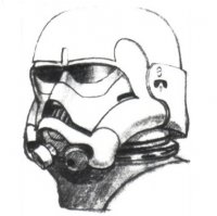
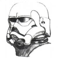
Helmet Time!!!!! Here's the untrimmed AP helmet. I love the fact that it has the trim lines molded into the ABS and approx screw locations too!! No wonder the stormtrooper's couldn't hit anything they shot at... So I started off drilling small holes in the eye sockets with a dremel and then moved the drill bit sideways to connect the holes and cut out the eyes. After that was a lot more sanding and filing than I expected. It took a long time to get the eyes looking the way I wanted. Mark
-
Thanks for the suggestions.....I managed to fix the little crack forming in the corner of my right shin. Here we go: Chop Chop Chop... Poured in some acetone. Spilled some on my cutting mat and immediately lost the paint off the mat. Wow, this stuff is strong. I waited a few hours, splashed in a bit more acetone.....waited longer.....mixed with a stir stick.... At this point it was getting late and the ABS paste was still pretty lumpy so I splashed in a bit more acetone and covered it to sit overnight. The next day it was nice and pasty... I quickly put a blob of ABS paste on top of the crack and below it. I was amazed how quickly it started to set. You have to work fast. Then I waited a little more than a day to make sure it was hard. The next day I sanded and polished the ABS Blob. Wow, good as new.... Next I heated up a small piece of cover strip material and shaped it to fit the area. I glued this in place to help re-enforce the shin hopefully stopped that area from continuing to flex when I am putting on the shin. It's not the prettiest but you can't see a thing from the top or front. It's all inside the shin and will be covered by my leg. :-) Mark
-
Alright, help!! I have an issue... During a test fit today I noticed I've got a crack developing in the top right corner of the right shin. What should I do? Mark
-
Hey Sean, I found I got amazing results with a table top belt sander (a cheap one is less than $100) for larger pieces, flat sides and smooth curves and then 200 grit on a rubber sanding block for finishing up. Mark
