

TKSnake
-
Posts
143 -
Joined
-
Last visited
About TKSnake

Recent Profile Visitors
3,235 profile views


-
Just a generic appearance from LFL but for 3 days. I thought it was going to be another Nissan Rogue commercial shoot and passed. Still kicking myself.
-
Tack marks look fine on a bin, but if we wanted to roll out patches or something that can be shown on a vest or shirt, they would get kind long-ish 😅
-
That's a very clear and thorough reply. Thanks for the explanation @themaninthesuitcase. You'll have to forgive me, it wasn't clear if my proposal was torpedoed or not. We all have lives outside the Legion, and I also understand that these discussions can cause people to become anxious. So please don't stress. If regular runs of precise quantities were run, the issue of extra stock would be a non-issue. It wouldn't even have to be that regular, perhaps once a year. Once somebody got the ball rolling, it might be easier to transition to new staff if need be. The sound of a running merch shop seemed odd to me as well because of not only with the reasons you mention, but with the initial purchase, possibly being left with unsold merch if things change, merch changes, interest dries up etc. To whoever is doing the initial order without a forecast, it could be a big loss to that person or group.
-
@Sly11 and @gmrhodes13, I have a genuine question. Been talking to my friends in JRS who mentioned this: It sounds like JRS is using a similar forum device to help members track their trooping count. I was wondering, if me, or somebody else, did this unofficially, based on the current metrics we use to recognize troop count on the forums, would there be an issue with this? Something as simple as a 3D printed pin could work; or something even as regular as a pin run set up like a coin run, where a collection is done, the order sent, and then stuff is distributed. If FISD staff didn't want to be involved, we could set something up so that it could continue even if staff changes, etc. I'm missing the details on this, but would be interested to know what happened to avoid any pitfalls. Honestly, if something were set up, we would only want enough to cover materials and postage.
-

TKSnake's ANH TK Repair & Electronics Tutorials
TKSnake replied to TKSnake's topic in Tutorials, Tips and HOWTOs
How to Make a Hearing Assist Please see this post here! -
Sometimes it's hard to hear in a bucket, especially if one has loud blower fans running. There are two main options people will use: use quieter fans (sometimes not an option in hot places) or use a hearing assist. Hearing assists can be tricky to install, but if you're handy with a soldering iron, they're actually not too hard to build using an off-the-shelf kit, extra wiring, and a shrink wrap. I did this work years ago for myself, but for those interested in learning how to become a maker, I'll include some additional thoughts here. My original build blog for the hearing assist Part 1: How to Solder I covered this in an older forum post that you can find here. Part 2: The Velleman MK136 Super Stereo Ear IMPO it's the worst-kept secret that this off-the-shelf kit is the heart of most hearing assists used in TK buckets to date, because it's prefab and inexpensive. When you're paying for a hearing assist that's put together, you're mostly paying for the person's time to put it together, which isn't trivial. That being said, with some time, effort, and slight modification, you can install the kit with the included microphones into your helmet, and wire them back to the main board for amplification to the headphones or ear buds of your choice. The kit is still widely available on Amazon and other online retailers. You can use this link to search Google. The kit is easy to assembly because the instructions are clear and all components are through-soldered. This means there's no surface-mount soldering, chips, ICs, etc. to solder. It's 100% analogue. Just put the leads through the board, solder them, and trim the excess lead with wire clippers. There are plenty of video tutorials discussing how to put these together (try these YouTube videos). However, before you add the microphones or battery pack, pay attention to Part 3. Part 3 - Modifying the Velleman to Use in your Helmet The Microphones For the default kit, the mics are soldered directly to the board, where you don't want them. They need to be mounted close to the outside of your helmet without being seen. To do this, you'll want to solder about 12" / 30 cm of lead wire between the microphones and board, maybe more depending on where you want to mount the board inside your helmet. An easy way to measure is to use wire or string to measure between where you plan to mount the board and where you plan to mount the microphone. If in doubt, give yourself extra wire. It's not hard to add more wire if need be, but it's extra work that can make an extra point of failure. There are two main things to remember when mounting your mics: They are stereo mics, so the left mic will need to be on the left side of your helmet, and the right mic on your right. * Otherwise, your audio experience won't match what's actually happening. The mics have polarity, so when adding lead wire, keep track of the positive and negative terminals of the mic. * If the mic does not work, you can de-solder the wires, switch them around, and re-solder them. * Bonus points: using Micro JST 1.25 male/ female connectors between the board and mics can make installation, uninstallation, and repairs easier. For mounting mics, there are other posts in FISD that cover that. Most TKs opt for two options: Make mounting holes under either side of the rubber brow gasket so the mics hide underneath the gasket Video by Matt Nelson here Make mounting holes behind the ear pieces, then use jeweler's drill bits to create miniature holes on the black ear stripe through which sound can travel to the mics. Video by UKSWrath here PRO TIP: bend the microphone leads at 90 degree angles before soldering and installation. This will be helpful when installing in either of the above locations. Also, protect and bare wires with shrink wrap or liquid insulation to keep your wires from contacting and shorting out. Here's my own helmet for reference: The Batteries The kit comes with a battery holder for 3x AAA batteries. This is fine but can be bulky inside of a perhaps already-cramped helmet. Some people prefer regular AA batteries though because they're easy to swap if power runs out. If you decide to stay with the 3x AA battery holder, do NOT fasten it to the back of the main board; instead, simply solder it to the board to alongside the board in the helmet. Otherwise, it will be too tall for it to be in the helmet while wearing it. you can even install it elsewhere int he helmet if you add more lead wire between the battery pack and board. Again, you can use JST connectors here to make installation easier, or to swap between batteries or USB power. Speaking of which, if you have an old USB-A male cable lying around, you can easily cut this and splice this into the power leads on the board instead, and run the system off of 5V USB-A power. Then just choose any USB battery pack you prefer. For this, the USB-A connector has 4 wires, but you only need to worry about the 5V and Ground wires, usually red and black respectively matching what you would solder for the AA battery pack or to a JST connector. PRO TIP: avoid battery packs that have auto-shutoff, since the hearing assist may not draw continuous power and such battery packs could shut off mid-troop. Speaking of which, for those with battery packs with more than one USB port: EM Noise and Battery Packs This is fancy stuff, and if you have separate power supplies for your fans and hearing assist, you can skip to the next part. Otherwise, if you're interested, please read. Running USB-powered fans off the same battery pack that's being used for a hearing assist can create EM noise for the listener, which is irritating and reduces the effectiveness of the assist. However, using a filter, like those used for old DSL lines, can mitigate or remove line noise. I wrote about my own experience when I assembled and modified my Velleman some times ago (see "Phase 2" in the blog). I don't use the helmet bracket anymore, but all of the electronics concepts for the filter and assembly still apply. There's an additional FISD post here that discusses it. Keep in mind that using wireless mics can also introduce noise on a hearing assist. There aren't any easy ways around this since the mic lead wires will act as antenna that pick up this noise, beyond using RF shielding, which can be messy and cumbersome. I tried it, but somebody more clever than I might have a better approach. Your best bet is to switch to a wired mic. I use a pico mic and have never looked back. Part 4 - Shrink Wrap or Encasing the Board The easiest way to protect your work is to use 3" shrink wrap. Cut a section long enough to slip the board into, plus a little extra at each end, then shrink it with a heat gun or (hair drier on the hottest setting).You'll probably need to cut through the wrap for the headphone jack, and ensure that your mic lead wires pop out one side while your volume (gain) knob pop out the other. Add labels if you're feeling fancy. There are also 3d Printed cases online, but the ones I've seen are for the assembly with the battery back mounted to the back of the board for the stock Velleman assembly, and wouldn't be useful in this application. But if I end up making an STL or finding one online, I'll append it to this how-to. Part 5 - Mounting We talked about mounting the microphones, but the main board and battery pack mounting is up to the wearer, so long as everything can connect when finished. My personal preference is having the knob close to the bottom of the helmet on the left or right side, so I can easily make volume/ gain adjustments without the knob being noticed. As for how to fasten, most people use double-stick tape or Velcro. The latter can make it easier to remove if the assist isn't needed or repair/ replace if something breaks, especially if JST connectors were used in construction. In my old tutorial, I mounted everything to a helmet bracket, but I later removed the bracket and mounted everything to the inside of the helmet with Velcro. Even later, I switched to mini blower fans, so I removed the assist entirely (the mics are still installed but not used). Summary It's all about time or money. There's nothing wrong with paying somebody to assemble a Velleman Super Stereo Ear for you, but if you have used a soldering iron before, or want to learn how to solder, this isn't a bad way to learn or practice. Either way, installing it can be the tricky part, but with a little extra care during construction, you can even make that a bit easier for yourself.
- 1 reply
-
- 2
-

-
Hash marks would be fine for bins, but kill marks might be a bit much. Good for TIE pilots, but for troopers? Whatever we use, it should have delineations of 5, 10, 50, 100, etc. Accuracy jokes aside, we're not talking about hitting anything except the number of troops under one's belt. Are Roman numerals used in canon? Even if not, we could use them for major troop milestones, like Albin has done with membership anniversary coins. Or we could just mike vinyl stickers for totes, cars, etc. when troopers

-
It definitely helps encourage people to trip for certain groups. I'll admit that I dodn't *need* to troop for swag, but having even just a patch or rocker to commemorate m one's 50th or 100th troop in armor would be a nice incentive. Without trying to sound trite, JRS does more for less. Certainly it's true that a TIE costume can be used for for several other costumes, but they rewards members for doing those troops. It's sounds like ACD and Pathfinders might be considering similar tacks to encourage membership and trooping. I've known some members who will choose TI over TK so they can get closer to some wings It's certainly harder to put together TK armor, but my argument is that the division does less to recognize hard charging troopers who have to take more time to get into and out of costume every time they troop, can't (easily) sit down or take restroom breaks, etc. Getting recognition, for example, Expert Infantry and Centurion is nice with respect to attention to detail and screen accuracy, but personally (and perhaps to others) it's not as important as representing the Legion, doing troops, and being a Bad Guy Doing Good. Based on past FISD swag, somebody could put together a Centurion costume, get a gold rocker for their patch vest and then troop in it once. Beyond forum recognition, FISD has never produced swag to recognize troopers who have busted their posteriors in the field. If such swag was tied into to current forum recognition program, it could encourage more forum participation AND more trooping. Obviously, qualified troopers would be paying for their swag once the qualified, and runs could be established on a regular basis to reduce our eliminate out-of-pocket expenses for whoever is coordinating the run. Currently, recognition on the FISD forms only extends to the forums. Unless I print out a digital badge and attach it to a ribbon. Sincerest apologies if that sounded salty.

-
Didn't know if there was a better forum to post this, but some troopers who saw my post on Facebook wanted to port the post here. Original post on FB: https://www.facebook.com/groups/www.whitearmor.net/posts/1658877511410535/ The train of thought started when I was talking to some garrison members post-trop and them talking about how JRS has certificates of recognition, and also physical items like silver and gold wings, for trooping milestones, i.e. the number of times they've trooped in a JRS costume(25 / 50/ 100 times, etc.). I'm wondering if implementing something like this would help with numbers. JRS has pushed FISD into 2nd place overall for most approved costumes, and although it's not a popularity contest, I've noticed at least in my area that it's been harder to get TKs together without concerted effort. FISD already has recognition for costume accuracy tiers, but having recognition for troops done would incentivize getting troopers ack into white armor. Arguably, suiting up in most (if not all) FISD costumes is harder than JRS costumes, but the only recognition we get is for costume accuracy, and maybe some forum swag, but that's about it. Some members thought we should continue the discussion here. Please feel free to leave your thoughts. If this topic has come up in the past, I apologize.
-
I've done this, but I also have miniature jeweler's drill bits that I used with the Dremel to make the holes as small as possible. When I used fans noisy enough to warrant a hearing assist anyhow.
-
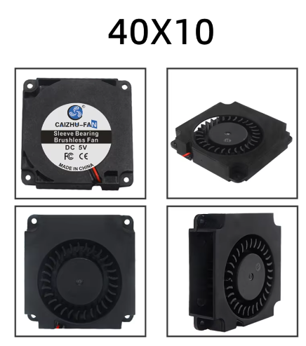
Personally, I just use quieter fans instead of big blowers. It reduces clutter and eliminates how much crap you need to put into a bucket. Wire 4x mini (laptop) blowers to a 5V USB power supply. Not as much wind as two big blowers, but easily more quit and definitely enough to help keep your bucket from fogging in all but the most humid conditions, especially if you have a balaclava to help with sweat. I use either 30 x 10 or 40 x 10 mini blowers; two near the bucket lenses and two lower behind the Hovi tips. Since I've never needed a cludgy hearing assist. My bucket is fitted with the mics but I've never needed to reinstall it (self-built based on the same kit that UKSWrath uses). It's floating around somewhere in one of my spare parts bin.
-
Barrel pt 2 and Receiver Assembly I finished printing out all the barrel parts and tripod parts. At this point, the only pieces left to print are the t-tracks. I finished glueing the inner and outer barrel assemblies up to the muzzle parts, except for Muzzle pt 5 that goes on the ned of the outer barrel. The other muzzle parts were glued together. In the image below, the muzzle is placed on the inner barrel but not glued, so that I can paint and finish the assemblies separately. The reason why I couldn't cut the outer barrel when it was mis-assembled is apparent when the inner barrel is inserted. They need to match perfectly at the muzzle so both assemblies connect there. For the receiver, I installed some shallow screws on the structural reinforcements I added, after drilling pilot holes, for additional strength and to help keep parts aligned during epoxy gluing. After using CA glue to add some structure for the electronic trigger switch (discussed next), there was nothing left to do but epoxy the front and rear right receiver pieces together. One the right side had cured for an hour or so, I dry fit and clamped the left receiver pieces to the right receiver assembly to ensure that there was no bowing an that the left pieces would be able to be bonded without issue. I finally obtained the fast action switch I want to install in case I decide to install electronics later. I wanted to mount it on the mounting arm on the right front receiver part, but I had to highly modify it to make way for the electrical contacts. After that, the arm was flimsy, so I printed some custom supports using MS 3D Builder to make some simple shapes to CA glue into place before major assembly. Once those were dry I bonded the right receiver pieces together as previously described. Then, I CA glued the switch into pace after adding lead wires for future use. Once the right had cured more, I commenced to epoxy the left front and rear receiver together, insert shallow screws in the reinforcement, and then immediately exofy that sub-assembly to the rest of the receiver. I had to use all my clamps for the latter. Notice that the left rear piece is missing the grip. For future electronics installation, I decided to make the left grip removable in order to install a USB battery or other components, since getting into the hollow grip without a removable panel would have been extremely difficult with everything glued together. I fastened a mini rocker switch into the panel to turn any future electronics on or off. I could have mounted it elsewhere but it was an easy instal that required little modification of the model. The additional blocks in the right receiver's handle are for mounting screws for the panel. The reinforcement on the other part of the left rear receiver also doubles screw mounts for the top of the grip panel. When the panel is mounted, it looks like it a natural part of the piece. Finally, the tripod legs are two parts each, but like the barrel parts, only connected together with weak, tiny tabs. I created some scaled-down sections based on the same legs, printed them, and inserted them in the hollow section of the legs to act as reinforcement. While I glued the left receiver to the right, I used the extra epoxy to glue the tripod legs together, and the front sight to the muzzle. Then I laid everything out on the garage floor. I do need to finish assembling the receiver top door, but other than that, I'm going to wait until I get the spray resin I purchased so I can start finishing assembly. The idea is to sand and apply a coat of spray resin to smooth the parts and also add additional strength before fine sanding, priming, painting, drybrushing, and a matte finish. More to come...
-
It's certainly worth future consideration, although one might have to worry about dirt and grime building up on the clear parts over time. I've also had to tear parts apart and glue them together due to bad layer lines, probably due to some extruder clogging. Overall, the epoxy joints seem to be stronger than layer lines. One thing I kept in mind was the "grain" of the print. most of the outer barrel was printed vertically, and the inner barrels printed horizontally, in order to "cross the grains" and further increase strength in the barrel especially. Overall, I'm considering doing a light resin coat on the outside before sanding, priming, and painting. Epoxy's an option but I would have to whip up a lot of small batches and apply it as evenly as possible to avoid pooling, which might be tricky and sticky. I'm currently researching spray-on solutions as I finish initial building.
-
Barrel: Overcoming More Poor Design Issues Waiting to get to the electronics shop to get the switch for the receiver's trigger assembly, I started focusing on printing and assembling barrel parts. The barrel consists of an inner and outer barrel, along with miscellaneous parts for front & rear braces, front site, and the end pieces for the muzzle. The main issue with these parts, like with the receiver, is that, besides some small male and female tabs, there's very little in the way of strong joints on these parts - they're all butt jointed together without any overlap or increase in surface area to make strong adhesion. Taking what I did with the receiver, I used MS 3D builder to slice up some barrel parts and make small connector pieces that would fit inside the barrel pieces, like pipe joints in plumbing, but inside the pipes instead of outside so they'd be hidden from casual view. This took some trial and error, but eventually I found some pieces for the inner and outer barrels that would be close enough but not snug, so I could easily CA glue them in place, and then epoxy two or more pieces together. For the inner barrel pieces, I printed these horizontally since their cross section would not offer a lot of surface area for printing vertically, even with brims. Thankfully, they also didn't require inside supports, making them super easy to print, with only the brim and a slight flat section to remove. I also decided to print these pieces in gunmetal instead of black. Ultimately, these pieces will be inside the outer barrel and not very visible, so I plan to only lightly sand, polish , and paint them in matte clear coat to preserve the PLA's actual color. Some of the muzzle pieces will also be painted in gunmetal but will have some paint and weathering added so they don't stick out too much. The inner barrel had 5 pieces number from front (muzzle side) to rear (receiver side). The outer barrel also has 5 pieces but numbered 1, 2a, 2b, 3, and 4, for no apparent reason. The outer barrel pieces were harder. I printed all but one vertically. Outer Barrel 1 was particularly tricky because it has holes near the very end of the print. I printed the pieces from last to first, starting with piece 4 (with the screw post) to 1. Pieces 1 through 2b I printed vertically, as seen here with the inner barrel counterparts. Piece 2a was high and popped off the print bed during printing (below, center). I ultimately printed this horizontally after running a small test print for feasibility, and although structurally sound, will require a lot of post work to remove print lines and support leftovers. I had the worst time with Outer Barrel 1 (which I'll show in another post). After about 5 attempts and a lot of filament, I discovered on Cura (my slicer) that I could uncheck the "print brim on outside only" to also print the brim inside the hollow part of the piece, and increase surface area to successfully print it vertically. Of course, I ran out of filament after printing about 95% of the piece, so instead of reprinting it again, I used 3D Builder to slice of the missing part, print it separately, and glue it to the end. One of the reasons I ran out of filament is because, for Outer Barrel 3, both ends are the same and aren't keyed to any particular direction, so if you don't check the Sketchfab image, you can easily glue it backwards, which is what I did, and the holes aren't in the correct position. Here's what that looked like: Unfortunately, I didn't realize this until after the pieces were permanently bonded with epoxy. Because sawing them would change their length, which needs to match up precisely with the inner barrels, my only recourse was to redo 15 hours of printing. Again, I was caught off guard by bad design. So.... while I reprinted those pieces, I used the bar clamp on the inner barrel pieces. Inner barrel pieces are easier since they are keyed in one direction and easier to ensure they don't get messed up. The reinforcement inserts were placed with CA glue, and then the pieces were epoxied together for extra strength. Once I had the outer barrel piece printed (AGAIN), I was able to use the bar clamp to get them in the CORRECT order and epoxy them together, shown below. Note how the holes from Piece 3 (the bigger diameter piece on the left) are right up against piece 2b. Also note: piece 2a NEEDS to have the holes oriented on the bottom so the tripod holder can be mounted correctly. Mounting the tripod holder first can help you keep track of proper orientation (Piece 4's flat part on far left is the top of the barrel). After piece 2a but before piece 1 is the AA mount. Piece 1 will be added with corresponding muzzle piece later. For assembly with epoxy, the bar clamp is indispensable and keeps the right amount of pressure on the pieces until the epoxy sets, and makes it easy to make sure the assembly is very straight (super important for barrels). Between this, the extra reinforcement parts between the barrel parts, and using 4 wall prints and 30% infill, I'm hoping for something stronger than the average PLA prop. Finally, I printed out the last of the inner barrel pieces and reinforcement parts. There's a muzzle piece between piece 2 and piece 1 which I also printed out in gunmetal. I'll finish up the barrel more after I get more printed. Until then...
-
Receiver, Pt 2: Reinforcing a Poor Design Late replay as I've been pretty heavily invested in this build, but I'll make new posts in the context of when the photos were taken. Also going to update the original post to include tools I've been using. I decided to build the hollow receiver; eventually I might add electronics, and it would be terribly easy to hide most everything in a hollow receiver. Printing the receiver parts required a lot of supports. I was apprehensive at first, but with the matte black PLPA, they popped out without issue. The hollow receiver is printed in four quadrants. I started with the rear quadrants to ensure parts would match up. Test fitting the stock was very satisfying. Eventually I was able to print all the parts out without too much effort. For all receiver parts, they were printed with the seam down and outside up, so that supports marks would be on the inside of the pieces. For the rear site, If I had to print this again, I't probably do 100% infill. The bottom ring is thin and fragile near where it connects to the rest of the piece, and I had to glue it back onto the main body after it cracked during test fitting. It should be strong enough now but I still think it may break in the future. I did some preliminary fitting of the top cover to the receiver parts. It required sanding down part of the rear lip so that the door could come down far enough to close over the rear receiver. So far the build parts have been clean and crisp. However, the one thing that bothers me about this kit is the lack of connector parts. For example, although the left and right sides fo the receiver have connection and alignment tabs, there's no such luxury between the front and rear right parts. For one of the most vulnerable joints in the build, where the weight of the butt stock and barrel assembly will be centered, there's nothing but a simple butt joint, the weakest of all mechanical connections. Finding some parts on thingiverse (later I would build custom parts with MS 3D Builder) I created some reinforcement shims the help keep the pieces together. Between these, using epoxy, and perhaps even spare hardware fasteners like shallow screws, I'm hoping this will be enough to keep the thing from possibly breaking in half during a troop. More to come soon as I have done a lot more since this.