

Thrawn's guard
-
Posts
479 -
Joined
-
Last visited
-
Days Won
9
Content Type
Profiles
Forums
Gallery
Articles
Everything posted by Thrawn's guard
-
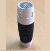
Lastly for this evening I thought that I would make a start on the ejector by removing the inaccurate moulded strip. I carefully used a Dremel to remove the majority of the material before witching to sandpaper and a file mail file to tidy everything up. I have a question for the E11 experts out there. I have seen that there is a section of the ejector on the right hand side that is rebated and has what looks like some form of slot and cylinder in it. Can anyone post a picture of this detail from a real Sterling ?
-
Next is a couple of close ups using green stuff. The first picture shows the result of boring out a thin layer of resin, filling with green stuff and smoothing before using number punches to create an imprint. Again this is a method that I have seen a few times which give a result that I really like, The next shot shows the results for repairs that can be achieved quite easily by using green stuff. The corner of the scope feet has material missing from the casting process. I took a small amount of green stuff and pushed it in to the correct locations ensuring that the 'blob' was slightly larger than needed. Once fully hardened I used a fine file to make it flush. Once painted there should;t be any clue of the original missing section of the feet.
-
Here is a couple of pictures of the front sight guard with texture added using a thin layer of green stuff which has been textured using the handle of a sculpting tool. This is a method that i have seen done a couple of time in various threads and I think that it works pretty well.
-
Nice tip thanks Michael. Here is a quick picture of what I got up to yesterday evening. I repaired the 2 holes that I incorrectly drilled in the folding stock. I also touched up a couple of areas that needed slight repair after being drilled. Once the green stuff has hardened I will smooth with files and sandpaper as required.
-
Having spent much of the evening looking in to the serial number insert shown above I decided to make sure that I would at least end the day having made some progress with my build. To that end I decided to carry out a few repairs using green stuff as well as adding texture to the front scope guard. I also added a serial number to the top of the magazine housing. I know that it will almost certainly be hidden by the power cells that I intend adding however it will be one of the small things that personalises this blaster. The other reason for doing this was that I wanted to practice using the punch in green stuff technique and this inconspicuious spot gave me the perfect opportunity. It turned out to be a good choice to do this in any event as I stamped my 3 the wrong way around, repaired the area for a second attempt then stamped it the wrong way around again. Well at least that was a lesson learnt. I will post some pictures during the course of tomorrow showing what I have described here.
-
This evening I have been playing about with trying to get a 3D printed serial number insert modelled and printed. I'm not too far off but due to the small size of the digits the print isn't quite achieving the quality I was hoping for. I have tried to fit the full 15 digit serial number format as described by T-Jay i.e. X00 0 000 X 0000 (X = letter and 0 = Number). All in all it has been a bit of a frustrating evening. This is a picture of it placed against the blaster to show roughly were it would be located. Do you think the stamp in green stuff is the better solution ? EDIT The more I look at it the less happy i am with the finish.
-
The scope is really coming on well. Do you plan to add any brass weathering effect ? I'm sure you will get your reticle sorted out. I'm not sure what I will do with mine yet or even what the requirements if any for centurion are.
-
Just a short build update for this evening. I decided to have a go at a working fire mode selector switch as this seemed one of the similar modifications and would give me a feel for what I needed to do for the working trigger modification. Firstly I placed the selector switch in the correct location checking that as it rotated around it could select the separate modes without fouling anything. Once I had a suitable position I drew around the base of the selector switch before rechecking that it was still in the correct position by placing the switch in the marked up area and pointing it in all 3 mode selection positions in turn. I then marked up the centre of the hole for fitting the selector switch pin. I then used a Dremel to drill out a hole in both the handle section or the base of the selector switch ensuring that the hole wasn't too deep i.e. I didn't want to drill all the way through!!! Once I had drilled the hole in both parts I checked the depth of each hole so that I knew how long to make the fixing 'pin'. I decided that I wanted to use a mechanical screw for the selector switch 'pin' for 2 reasons. Firstly I didn't want any issues with the resin cracking by using a screw where the threads were too deep. Secondly the pitch of the threads is much shallower on a mechanical screw so as the selector switch is operated the switch wouldn't be slack in one setting and stiff in the opposite setting (I hope that this makes sense). Two lines were then marked on the mechanical screw. The line on the far right shows the length of screw which will be located in to the handle section and the next line shows the additional length of screw required to fit in to the base of the selector switch. The rest of the screw is not needed so I used my Dremel with a cutting disk to carefully cut the head section of the screw off. I also wore safety glasses as I did this as I have had a number of cutting disks shatter during use in the past with bits of disk flying off in all sorts of directions (Better to be safe than sorry). All that needed to be done now was test fit the selector switch to make sure it fit and worked well. Once test fitted the switch is removed until painting and final assembly. Thankfully all seemed to work fine....so back to researching and deciding what part of the build to look at tomorrow, A quick message to anyone out there who is tempted to have a go at modifying a resin blaster but feels a little worried that they won't have the ability I would say give it a go. You only need to do small bite size chunks of work at a time and when it is broken down in to these small tasks there really isn't anything that I have come across yet that is particularly difficult. The community on here is also very helpful and knowledgeable. Also if you do make a mistake it is not the end of the world as most are easily repairable using a 2 part modelling putty called green stuff (You basically mix a strip of the putty together with your fingers, sculpt to the shape required and the putty will then set. If needed you can then file or drill it as you would with the resin that the model consists of. EDIT - Later in my build thread I carry out a improved method of installing a working selector switch.
-
I was going to look at the working trigger modification this evening but thought that before I did so I would ask the communities' opinion on the following: - I would like to have a stiffer trigger mechanism than a ballpoint pen spring would provide. Has anyone tried interlinking 2 ball point pen springs within each other to double the stiffness ? Alternatively can anyone think of a cheap source of a similar sized but stiffer spring ?
-
I really like the look. I'm also wondering if the serial numbers came out perfect on the real Sterlings or if there were variations in the quality of each stamped digit. If the original serial numbers sometimes tended to have variations then perhaps what you have here already accurately represents what you are looking to achieve. If not then it may be an option to try to remove only the area local to digits that you are not happy with, reapply green stuff and restamp. I will also be looking to add a similar detail so this procedure is very interesting. I originally considered actually stamping a small strip of metal and then incorporating it though I have no idea at this stage how easy or difficult that would be or how well it would turn out.
-
Full resin E-11 from DoopyDoo's with some modifications
Thrawn's guard replied to T-Jay's topic in ANH BlasTech E11
Hi Tino I'd not realised that. I recall seeing wires on screenshots from some official Star Wars sources but assumed that they were from actual movie footage. -
Hey Michael thanks for letting me know. I'm not 100% sure myself as I seem to recall seeing it on either side (I may be wrong). The good news is that I designed the pin sight housing as a tight fit item so I can slide it out and put it back in the other way around. I can also twist the sight pin around 180 degrees if needed. This may have been the original design which would explain why there may be conflicting reference details. Is there anyone on here who has a real Sterling who can advise?
-
Thanks Michael. I'm trying to do whatever jobs I can whilst I wait for the completion set. In many ways it is working out well as it is giving me the time to do some research between each section of the build. I'll have to look and see what I can get on with tonight.
-
This build has been added to my reference library. It's another example of some fantastic work which has resulted in something that you can be very proud of.
-
Michael this build is getting better all the time. I particularly like you use of a switch in the magazine release button (and your serial umbers look much better). I will need to look in to how to paint up my blaster at some stage too so I will watch your progress with interest.
-
As I was just putting all my tools away I came across this (It is the handle of one of the sculpting tools I just bought. It looks like I have solved the problem of finding something with the correct texture for the front sight guard
-
Unable to find something with a texture that I was happy with to add the texture to the front sight guard I thought that I would do some work upgrading the Doopydoos folding stock. Where to begin.......Well I decided to go for the obvious and open out the holes along the length of the folding stock. First of all I drilled some pilot holes to help keep the larger holes that I would drill next located in the correct position. Next I needed to open up the underside of the stock so that I can install the cylinder from Tino's completion set when it arrives. I decided at this stage to only remove the resin local to the holes that I had drilled through. That way I can then increase the length of the recess to suit the actual cylinder length later. To do this I drilled a line of holes carefully making sure that I did not drill all the way through. I then used a rotary grinding bit on my Dremel to remove the remaining material and tidy things up. Next I drilled through the hole locations (One at the very front of the stock and one halfway down. As a final job for today I decided to cut away the material in the end of the stock release lever. Firstly I marked up which part of the recess was to be opened up all the way through (Basically I looked at the line of the underside of the stock and drew a line projecting this line through the area I was modifying). The area of resin that I have coloured in is the section that is retained (The rest is removed). I then drilled a line of holes in the area of the resin to be removed. TIP - Drilling from both sides rather than drilling all the way from one side prevents the drill bit emerging in the wrong location. The fine engraving bit can then be used to remove material between the holes. Once drilled and opened up a fine file was used to smooth the slot (It was actually a disposable nail fine which is useful here as they compress so the file itself exerted the pressure on both top and bottom face of the slot as I used it. The area that I has previously shaded in does not get removed however it is supposed to be a section of the main stock arm that you can see through the stock release handle. Therefore the edge should be made to match the bottom edge of the main section of the stock. For example this is not a hard edge it is actually rounded off to match the rest of the stock arm. I have a little more cleaning to do on this but here is what it is looking like at the moment. Well I only intended working on the blaster for an hour or so today and ended up spending much longer than that.........I seem to be addicted. As always if anyone has any suggestions or comments they will be most welcome.
-
How to: Make your own M40/M39 E-11 Blaster Scope
Thrawn's guard replied to aliens8us's topic in Tutorials, Tips and HOWTOs
Nice work Jonathan. I think if you made the feet, filled joints with green stuff added some lenses plus painted and weathered it this could look really good. I would be very interested to see how this progresses. -
OK time for another progress update. This is the humble beginnings of my front sight pin. I decided to use a screw because I wanted to replicate the look of the original Sterling sight and it also allows me to actually screw the pin in to the housing. I then screwed it in to the end of a piece of wood that was secured in a work bench. Having done this the first task was to carefully cut off the head using a cutting disc on my Dremel. Once the head had been removed I began to shape the end of the screw shank using a grinding tool on my Dremel. Using a cutting disc I then formed a vertical groove in the thread of the screw which is a detail used on the actual Sterling sight (The grub screw is then fixed through the side of the housing and locks the sight pin in the correct orientation), Using this method once the grub screw from Tino's completion set arrives I will be able to install it and secure the pin in a similar manner to a Sterling. In reality I didn't really need to do this or glue the pin in because it screws in tight. I then cut the pin off the rest of the screw (I decided to cut it off a little longer than required so that I could then grind it to the correct length). When I test fitted the pin the sight pin was as suspected too long, (better too long than not long enough), so screwed it in the the housing that I 3D printed so that I had something to hold it with and shortened it by grinding it down so that I would get the correct hight within the sight surround. At this stage I also slightly reshaped the profile of the pin to make it more accurate, It seems like a lot of work on such a small detail but it was something that I wanted to try to make as accurately as possible.........it was also fun :-) I still need to texture the surround but I feel that I am now starting to make some progress and am getting used to using the tools and working with the materials. I understand that only part of the sight surround is textured so I will get back to my research to see exactly how much.........Unless anyone has any good reference pictures that they could post.
-
Jason - I used the method Adam mentioned above and it separated the parts from the base very nicely. The other big advantage is so long as you don't press too hard there is little chance of any mishaps and you will have very little clean up to do 9It doesn't take long to do either) I would suggest getting the degree finished then starting your build.......just my opinion but the degree is very important and i'm sure you have put much work in to it over the previous few years. The blaster can wait for a few weeks :-) Good luck with both your degree and your build.
-
The triangular file was really useful (I bought it as part of a set of 6 different files and it wasn't expensive). Depth wise I kept a good eye on things and managed to avoid going too deep. The depth of the front sight pin housing modelled is such that if the slot is formed for it to slide in it doesn't cut too deeply in to the top of the barrel and in this was acts basically as a template (Probably more luck than by design). last night we had family call over of a couple of days so I didn't get the chance to do as much work on the blaster as I intended however I did print off the latest version of the front sight pin housing and test fit it. It is not too easy to see but I now have the vertical circular hole for the sight pin to fix in to and also the horizontal hole from the side for installing the grub screw once it arrives. I also need to look in to whether I need to sand down the base of the sight surround to get a closer fit......More research i guess unless anyone can tell me if this is what the detail is like on the actual sterling sight surround.
-
Great work with your cylinders so far. I can't wait to see them finished.
-
It turned out that my Flashplayer on both my home and work computer was out of date. The solution is either update your Flashplayer or if using Internet explorer use google chrome instead. @ aliens8us - Nice picture.
-
Full resin E-11 from DoopyDoo's with some modifications
Thrawn's guard replied to T-Jay's topic in ANH BlasTech E11
This is another unbelievable thread on a amazing blaster and a great resource for my own build. There are many items here that have inspired me and given me great ideas. Tino one quick question. Can I ask why you decided to not use wires connecting to your power cylinders ? Was it just personal preference ? -
I am really enjoying this build and are trying to take on board as much as i can from the many amazing builds on this forum. I would however like to try to come up with something something new/improved to contribute the the community however I am struggling as each element of the build I think about already has a number of fantastic examples. I'll keep thinking and maybe come up with something to post on here.
