

Suspend
-
Posts
157 -
Joined
-
Last visited
-
Days Won
2
Content Type
Profiles
Forums
Gallery
Articles
Media Demo
Posts posted by Suspend
-
-
Nice work, Greg. I've been lurking in the background following your build to see what I'm in for. I'm starting my own AP build as soon as I finish my blaster.
You look awesome!
Mark
-
Scope done? :-)
Mark
-
 1
1
-
-
Just now, T-Jay said:
The 3 bigger screws on the outer edge sit on top of the surface, while the 2 smaller ones are about 1mm under the surface.
That was fast. Thanks, Tino!!!
Mark
-
1
-
-
17 minutes ago, T-Jay said:
Please don't feel pushed, Mark. I just wonder when people upgrade their build with a completion set and skip the easy mods. So in this case at least it turned out useful to mention it. No worries, adding these screws is not a big thing (done in a few minutes) and is the exact same effort now.
No, T-Jay, I definitely don't feel pushed. I appreciate the reminder. I totally forgot about the screws. I'm sure I would have noticed eventually as I have all the parts from your kit in a Tupperware box. I just have to check some photos to see if the screws are recessed or sit on the surface.
Mark
-
6 hours ago, T-Jay said:
Additional work on the power cylinders looks good and helps bringing them closer to the real thing.

Very good build progress on the scope. I just wondered that the front section had to be destroyed to get the lenses. Was the connection glued instead of screwed?
Are you not going to add the 5 metal screws on the scope front?
DOH!!! I totally forgot the screws.
 Scope not done...
Yes, the black lens tube was glued to the chrome plastic housing.
Mark
-
Most Impressive......
(Spoke like Lord Vader, of course)
-
1
-
-
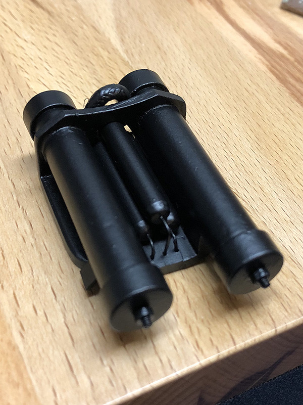
Oooh, good. Thanks, T-Jay. I was actually working on the scope this weekend. But first let me quickly wrap up the power cylinders.
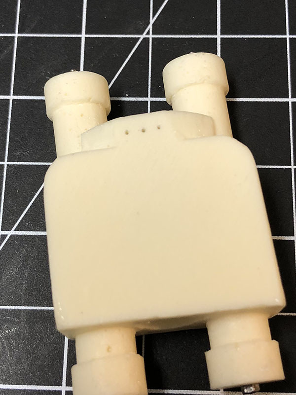
With the gentle nudging from T-Jay and DracoTrooper, I did go back and make two more changes to the Power Cylinders. I added two little "wing" tabs using the ABS sheet from T-Jays Completion Kit and then I sanded down the edge of the power cylinder frame to make them angled. But just the sides. I couldn't do anything with the middle as I had already wired up the back of the fuses with the red wire. Here's a couple of photos:
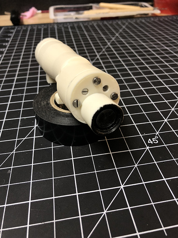
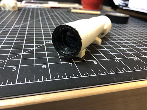
Ok, the scope...
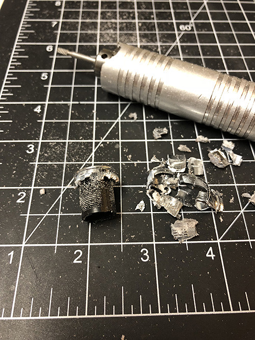
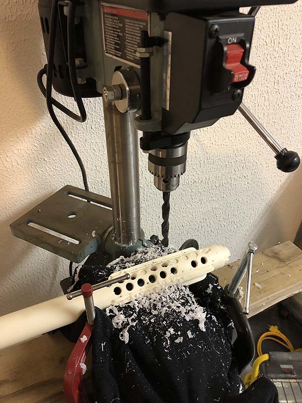
I started off with the grand idea that the scope would be fairly straight forward. I have a drill press (pillar drill) and I already have some spade bits. I set off marking the center of the scope and went to the drill press...
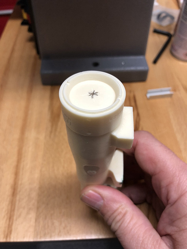
And that's about where things took a turn. I tried using the drill press to hollow out the scope but about 1 mm in I could already see the drill was going too fast to be able to aim down the tube. As soon as the spade bit reached the frame of the lens I could see it was off and I lost a bit of the lens ring. I immediately stopped. The drill press was out.
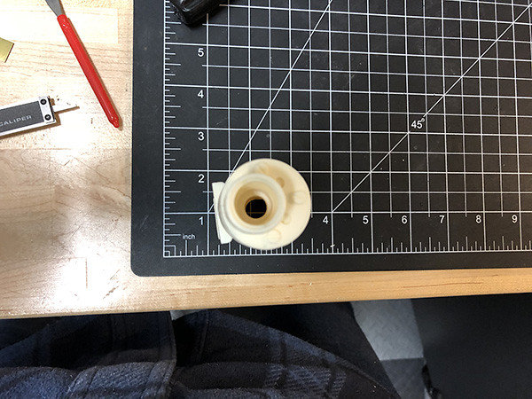
Back to my friend the dremel. I found I had way more control with a burr tip. I used the burr to go in about an inch. Widening the hole as I went. Then I used a larger sanding drum to open and round off the hole to the correct size.
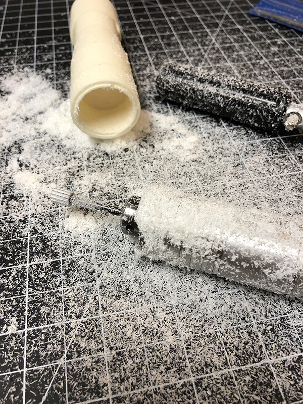
Once I had the opening to the correct size, then I went back to the spade bits but this time in a hand drill. I found it a lot easier to use a spade bit once I already had the opening a good inch deep. I could angle the bits slightly as I was heading deep into the scope tube to avoid getting too close to the sides. Once I was fairly deep I switched back to a regular drill bit. Similarly, I used several sizes of drill bit on the smaller lens end (front) and then drilled at an angle toward the main shaft. Surprisingly, both holes met up fairly uneventfully.
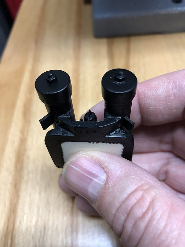
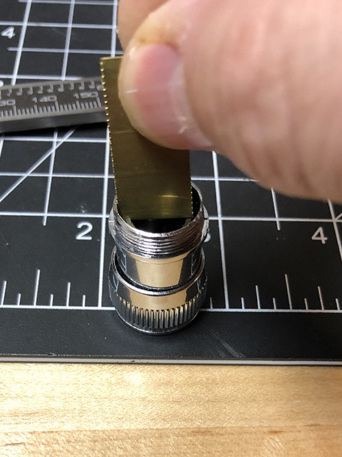
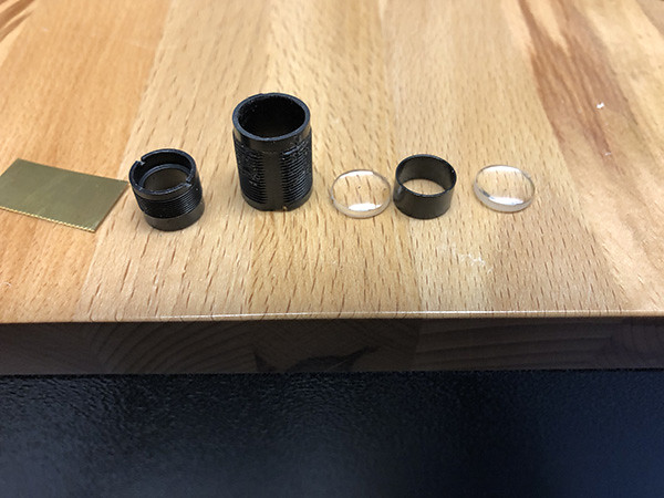
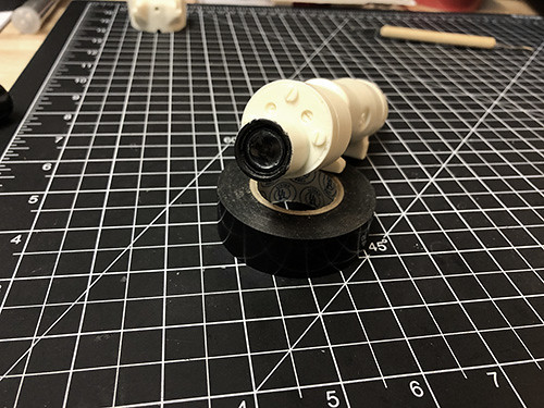
Next I took apart the monocular from T-Jay's kit. You can see how the monocular comes apart from his pictures one message back. Unscrewing the pieces was easy but I ended up cutting a little sheet of brass to unscrew the smaller lens. It needed a tool to fit in and unscrew the inner lenses and I didn't have a pocket knife as shown in his photos. Ya gotta make due with what you have. :-)
Once I removed the lenses then I started breaking apart the chrome outer plastic, as well. I wanted the lens housing from the center. I ended up using a burr tool in the dremel to carefully cut away the plastic.
What I was left with was the smaller lens pieces.
Next I used CableGuy's fancy trick of using Playdoh and a lego flag pole to help glue (CA) one of the small lenses back into the lens tube.
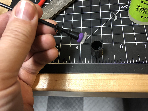
And used E6000 to glue the cross-hair lens onto the bottom of large lens.
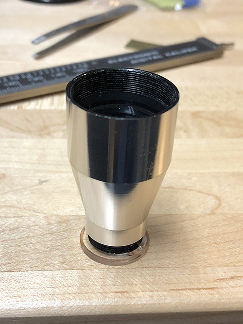
At this point I used a sanding drum to get both ends of the scope to the right size. The large lens with the cross-hair disk could fit in the large end of the scope and the small lens tube with the lens glued in the front could fit in the small end of the scope. Once everything was dry I sprayed some flat black paint into the inside of the scope to stop reflections. And when that was all dry I used E6000 to glue the small and larger lens tubes in place. Woo-hoo!! Scope done. Except for paint.
Mark
-
2
-
-
Hey Dan, thanks for the quick response. I just happen to have a Lego flagpole, play-doh and superglue. I'll do the same. :-)
Mark
-
2
-
-
Hey Cableguy, can I ask you about your scope? I see how you hollowed out the eye piece to insert the monocular part end the end, but what did you end up doing with the front? Did you drill out the front lens area and leave it open or did you insert a lens in the front, as well? Also, if you inserted a lens in the front, was it just a glass disc or did you find a way to insert the other end of the monocular too?
Thanks!!
Mark
-
You know, I looked at the shape of the backplate and I really thought about the wing stubs.....but then a little devil appeared on my shoulder and said, "Don't forget you have a full set of AP armor sitting in a box in your bedroom just waiting to be assembled..."
Ugh, I may have to go back tonight and revisit the power cylinders...

Mark
-
1
-
-
Thanks guys, the kind words mean a lot. There really are a great bunch of people here.
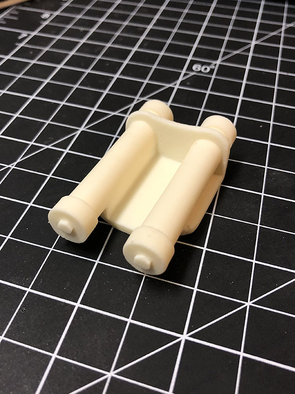
Next up....the Power Cylinders...that's what I'm calling them...I don't think I did anything special here. Pretty much the usual "Power Cylinder Procedure" that I've seen in other builds.
Here's how they started from Doopydoo's kit:
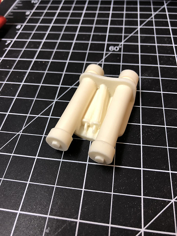
Many people don't like the way the 3 central fuses are mounted and overlap each other. So there is a lot of very careful dremeling and a lot of very careful filing and somewhat careful sanding to get rid of them. I used a dremel to get the large chunks away and switched to box shaped needle files to clear out the rest of the resin. It was a lot of work...
All gone...just like they were never there.
Selfie....
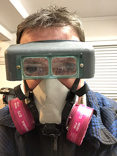
These head mounted magnifiers are like a gift from heaven. There's no way I could do all this detailed work without them. Note the layers of clothing. It's "January-in-Canada" cold in my garage.
Ok, back to work. I used a flat needle file to file off the resin bolt heads from the ends of the power cylinders, then cut the tiny, tiny, tiny bolts from T-Jay's kit in half and mounted them (with the nuts) on the fronts and backs of each cylinder.
Now it was time to make some more use of my Dad's old jewelry tools. He had some drill bits that are super small. I believe I used a 0.55mm bit to drill holes for the fuse leads in the bottom of the power cylinder block.
Next I used the aluminum rods supplied by T-Jay and cut out three replacement fuse pieces.
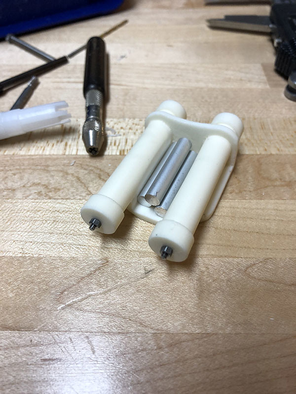
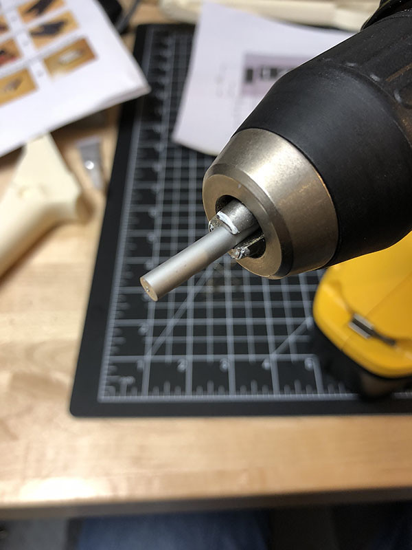
The using the same tiny bit, drilled holes in the ends of the fuse pieces.
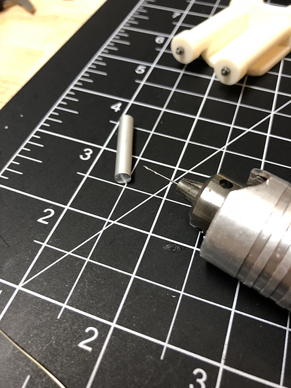
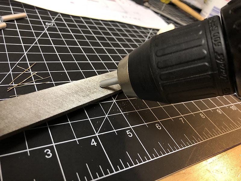
I can't recall which build thread I saw this in, but someone put each fuse piece into an electric drill (instead of a drill bit) and drove along a metal file to taper the ends of the aluminum rods. This was a great idea but it did leave a few scratches in the aluminum from the teeth of the drill chuck.
Then I used a mini-drop of CA glue to hold the little pieces of wire in the ends of the fuses. Not sure if CA glue will actually do much since it's aluminum, but it seemed to work ok to hold them in place for the next step.
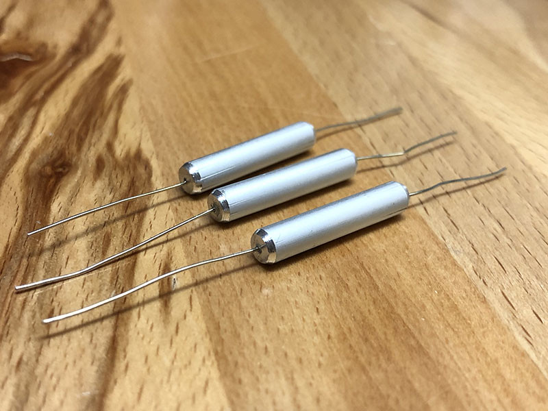
I used a bit of "green stuff" to create the end caps for the fuse thingy's. I know the end caps aren't shaped correctly, but the end caps are so small, I doubt anyone but WhiteArmor readers would notice.
I cut a hole in the rear of the fuse block so that the fuses could fit in through.
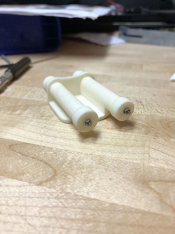
Then I painted the inside of the fuse block black and painted the aluminum fuses with primer and then black as well. I figured it would be hard to get spray paint in there later so I would get better coverage now. After they dried I glued them in place with E6000 and started to work on the wires. I carefully bend right angles on the front leads and fed them into the little holes I drilled in the front. For the rear, it looks like the original cylinders use 1960's resistors. I couldn't find any in my parts box but I found some 1980's resistors. Close enough for me. I glued 2 together for each side and used T-Jay's red insulated wire to wire them to the aluminum fuse wires. Yes, I actually soldered them as if they were real electronics. Here's an "in-progress" shot....and you can also see the "tiny drill bit" case in the background.
Finally, the whole thing got a coat of matte black. Again....weathering to come at the end.
That's it for the power cylinders. I'll probably do some catch up work next on the easier stuff.
Mark
-
2
-
-
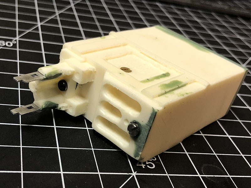
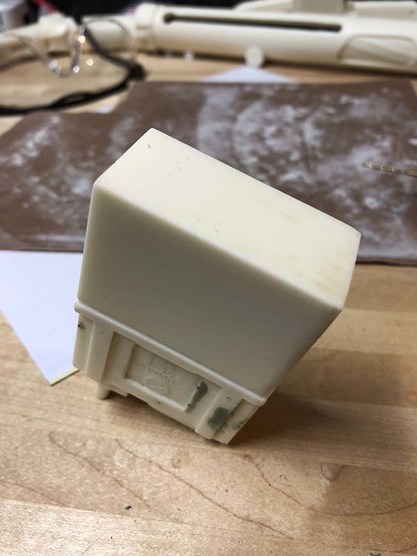
Ok, I've FINALLY made some descent progress on the counter. First up I used some cut up cigar box nails (really small) to fashion pins to hold the counter reset button in place. This is to give it some added strength in case it gets bumped. Hopefully it won't break off so easily.
Then I added the screws from T-Jay's kit as well as one of my own to the counter. Replacing the poorly cast resin ones by grinding them out with a dremel. I also glued on the top plate and window that I made (correctly positioned this time) and filled the edges with "green stuff" to hide the seams (again).
I should mention, I really didn't like working with "green stuff" at first. It's REALLY sticky. It kept sticking to my fingers and to any sculpting tools I tried to use to smooth it down and shape it. I got so fed up that I went to a local hobby store and picked up some modelling putty. It was Squadron Products fast drying, white putty, hobby filler. But you know what, I didn't like that either. It's a cream that goes on easily, but it's kind of "sandy" in texture and, worst of all, it wants to keep that sandy texture when it gets painted. Almost like wood the way it absorbs paint instead of paint sitting on the surface. Anyway, I went back to "green stuff" because it takes paint like plastic. Super smooth. And I learned to keep a bowl of water handy when I'm working with it. I keep my fingers and tools wet and the "green stuff" behaves better.
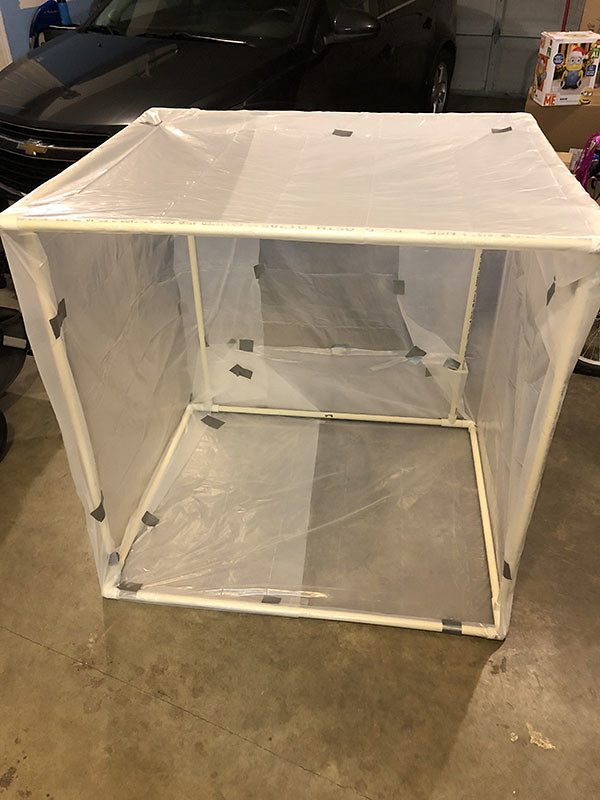
I was getting really anxious to see what the counter would look like painted. So I took a break and built a little spray booth using 1" PVC plumbing pipe and some plastic "drop cloth" painter sheets. It's about 3 1/2 feet square. It's kinda cold this time of year and it's gonna rain for months so I can't paint outside. This way I can paint in the garage where it's at least a bit warmer.
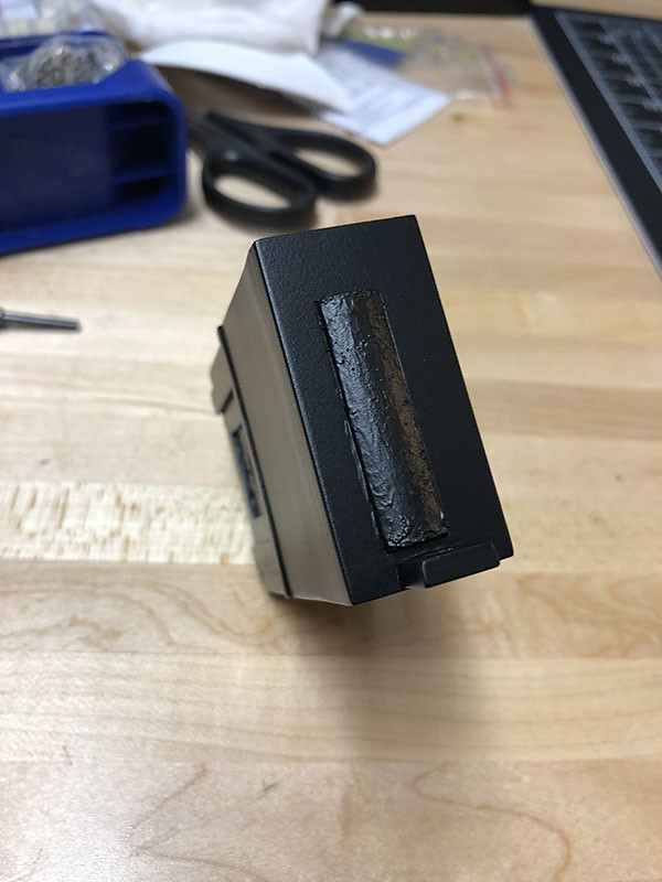
I also did something a little different with the counter window. Instead of trying to mask it off with tape, which would have been really difficult, I painted it with liquid latex. I dressed up as a zombie for Halloween last year and I still had some liquid latex left over. I gave the clear window about 4-5 coats, letting each one dry for several minutes before I started the next coat. This formed a barrier to keep the paint off but still something I could peel off easily. In this case I think it worked better than tape.
Ok, big reveal....
Here's the counter with the liquid latex barrier still on...
And with the latex peeled off...
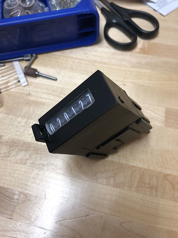
From the side:
And a before/after:
I'm pretty happy with the way it turned out. Makes me feel good about my first build.
I'm not going to do any weathering yet. I'll save all that until the end.
I think the power cylinders will be next...
Mark
-
6
-
-
Time for an update...
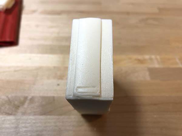
I originally toyed with the idea of using a dremel to cut a recess into the top of the counter and place a photo of the counter numbers in there. Then covering it with the "ruler" window I made. But I was really nervous about using a dremel to cut a perfect rectangle and there wouldn't be much room to get a file in there to clean the edges. So I had a new idea....
I've got some spare plexiglas scraps laying around so I cut one of these scraps to the same dimensions as the top of the counter.
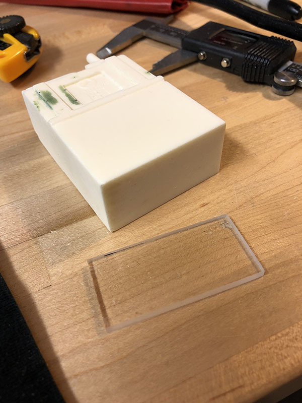
Then I sanded the same thickness off the top of the counter. This way when I glue this plate to the top of the counter, the counter (as a whole) will still be the correct dimensions.
Using the measurements from the Hengstler template, I marked the plexiglas with the locations of the counter window and the reset button.
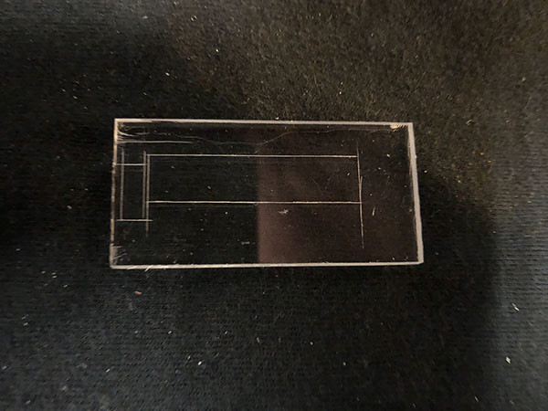
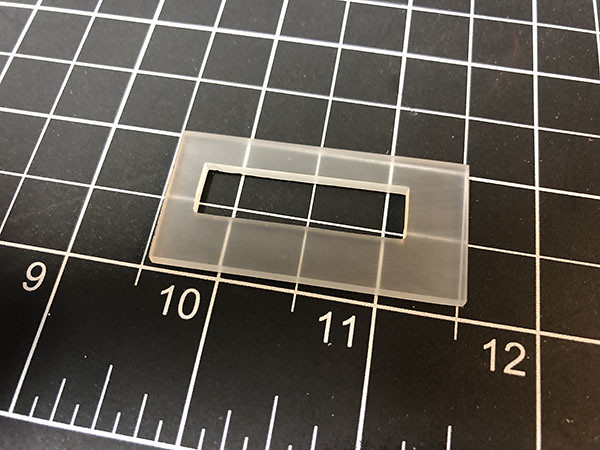
Then I cut out the rectangle for the window and filed it down so that my ruler window would fit inside. I actually had to make a second ruler window because my first was too thin now that it was to fit inside this new top. Luckily I still had lots of ruler left. (Now there's a sentence that possibly no one has ever used before. A friend of mine and I like to pay attention to unique sentences that may be new to the world.... "Luckily I still had lots of ruler left." This might be the first time anyone has ever said those words.

I decided against cutting out the area for the reset switch. There's just not much plastic between the reset hole and the window hole and I didn't want to break things. So the reset button will be glued onto the surface later. I can re-enforce it with some little nails to help stop the reset button from breaking off.
Next, I borrowed SIMpixel's counter number template from his build and made a few modifications of my own using Photoshop. I had some test numbers printed out at my local photo store. This example shows two different font sizes along with white borders and no white borders.
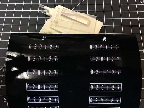
The idea is to cut out the numbers and glue them to the counter. Then glue the new counter top and window onto the top of the counter, over the numbers. And that's what is drying right now so I don't have any photos yet.
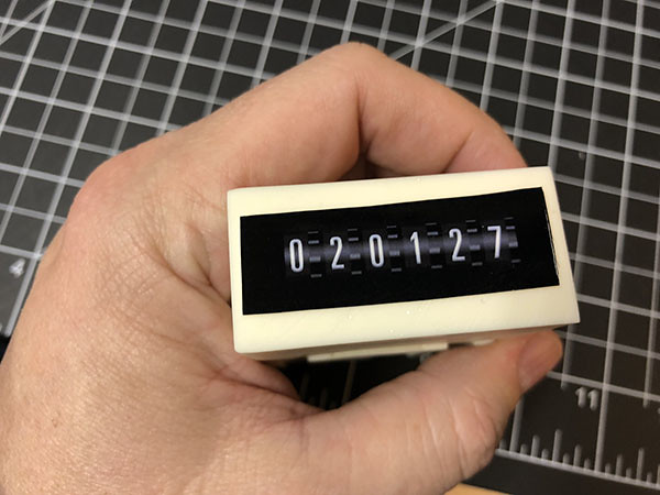
Also, I may as well mention that this progress didn't go exactly as planned. For my first attempt, I ended up gluing the numbers in the wrong location and glued the top onto the counter, also in the incorrect location. I had everything upside down. Of course, I only noticed this after filling all the edges with green stuff and getting it all perfectly sanded smooth.
 I had to pry it all apart, sand down the glue and green stuff and start again. Luckily I printed out several counter samples and I could also reuse all the parts after sanding off the old glue.
That's it for now.
Mark
-
4
-
-
Hey guys, I'm working on an E11 build and thinking ahead to paint. Most of the build threads I've read use Humbrol spray paint. Often grey primer, then a metallic silver, followed by flat black. Now for some reason Humbrol Spray is impossible to find in Canada. I've checked most of the big hobby stores in the Vancouver area as well as online all over Canada and I can't locate any Humbrol spray cans. Lots of the little Humbrol tins but no spray.
So, my question is: what is the general opinion of using Tamiya paints for this purpose? I noticed Humbrol is acrylic and Tamiya is lacquer or synthetic lacquer. I'm concerned about getting into a situation where I'm following and example from the forum (such as using a Hammer paint from the hardware store) and finding out that it doesn't stick to Tamiya.
Thoughts?
Thanks,
Mark
-
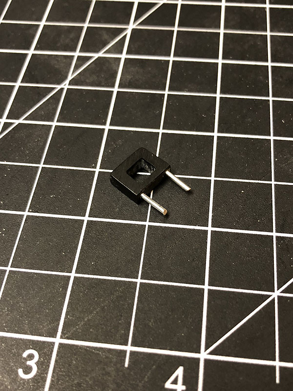
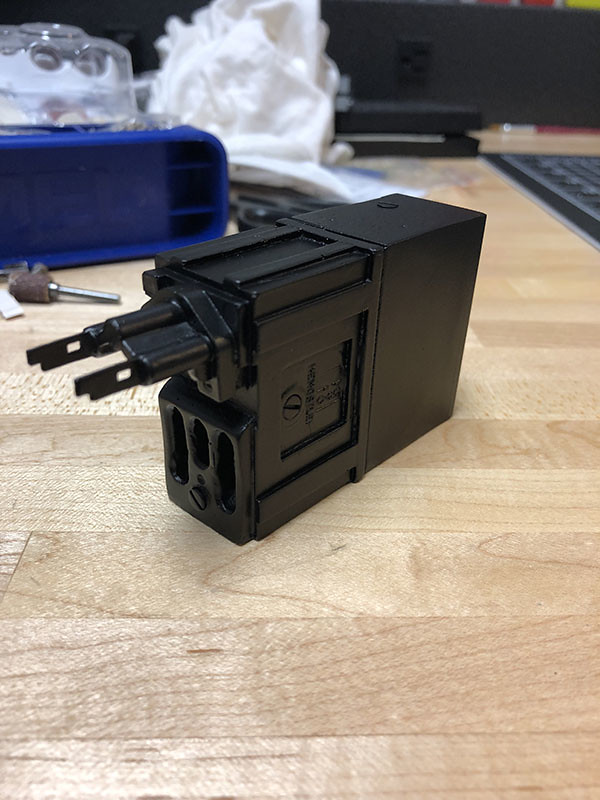
I worked a little more on the counter today. Grabbed an old car fuse and chopped it up. Used the parts for the electrode part of the counter. It may be a little "idealized" but I like the shape of the contacts. :-)
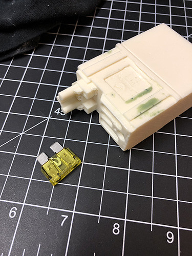
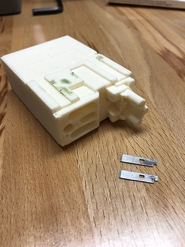
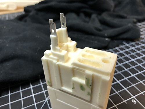
I also drilled a small hole in each of the metal fuse parts in the side that fits into the socket. That way the glue has a little more to grab. Just needs a bit of "green stuff" to fill the tiny gaps either side of the socket where I had to cut the slit for the metal parts.
Mark
-
2
-
-
I just thought I'd throw in my 2 cents on undersuits as I've been researching them for my TK build. The ones I'm thinking of ordering are from Renaissance Dancewear.
http://www.renaissancedancewear.com/stormtrooper.html
They claim to be the undersuit provider for the Episode 1 promotion tour so they should be pretty authentic. Not the cheapest but it looks like they are custom made to your exact size. Plus an optional zippered crotch. :-)
Mark
-
Thanks all for the kind words.
Chris, yes it is a Foredom, an old one. :-) It works great but the flexible shaft does take some getting used to. It feels like it's fighting you at times.
I spoke with T-Jay and he says the height of the reset button is 6.5 mm in case anyone else needs to know.
Back to dremelsville....
Mark
-
1
-
-
Awesome. (Photos worked)
Next I drilled out the lower vent holes on the main tube...
I inherited a bunch of my dad's tools when he passed away. He used to be big into woodworking and jewelry making. I knew these tools would come in handy one day. He also had a flexible shaft dremel like device that you hold like a pen and the motor hangs on the wall connected by a 1 meter flexible shaft. Should make some of the cutting and grinding work easier.
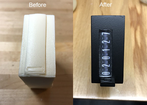
At this point I stopped working on the main tube and went to the Hengstler Counter. I filled a few tiny bubbles with "green stuff" and started working on the counter. The little reset button on the Doopydoo's looks wrong and I wanted a window with the numbers inside not the solid window of the Doopy's. So I sanded down the fake window and button. Sadly, I also lost the "Hengstler" text on the front, but it was so faint it would have probably filled in with paint anyway and been lost. You could barely see it on the photo...
Before:
After
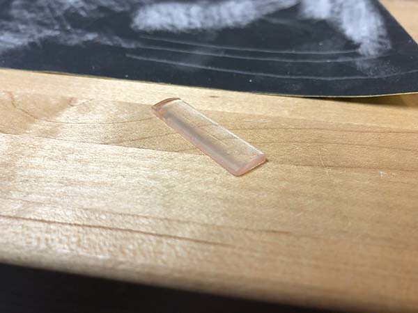
Next I needed to make a window and new button. I'm sure not a master dremel-man creating curved plexiglass using nothing but skill and a beer, but I think I've seen clear curved plastic before. A trip to my local office supply store revealed this ruler...
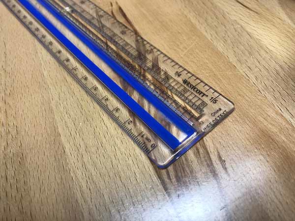
It's got a nice curve over the blue paint...
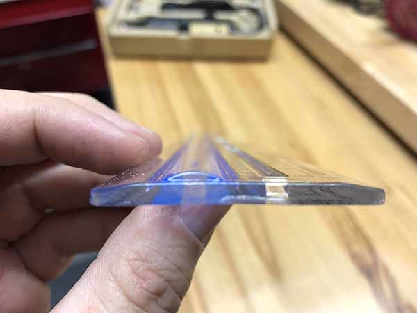
And the blue paint comes off nicely...
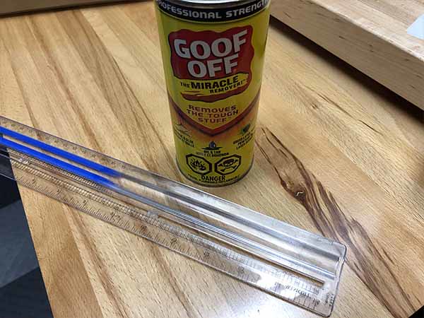
I got the size from the FISD Reference Page. Chop-Chop, Dremel, Dremel.....one Hengstler Counter Window...
Next a found I had a piece of smoked black acrylic, so I chopped this up to create the reset button. The same reference page showed the length and width of the button, but not the height.
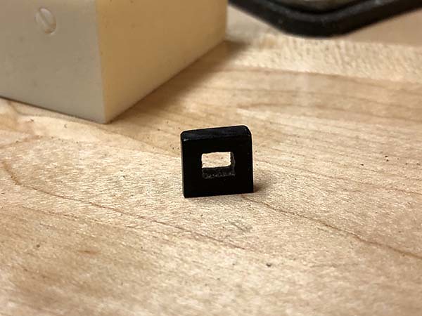
The reference page shows the reset button is 3.5mm in width and 10.5mm in length but it doesn't state the height. Does anyone know how tall the reset button of the Hengstler Counter is supposed to be?
Thanks,
Mark
-
2
-
-
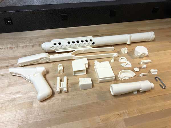
Hey guys, I've been reading the forums and "lurking" for a several months. After a bunch of research I decided on buying a Doopydoo's E11 along with T-Jay's Completion Kit. I think it's the best "bang for the buck" and leaves a lot of room for modifications. I'm amazed at the quality of T-Jays build. I probably won't be able to devote enough time to do all the mods in the completion kit, but I'd like to do enough to take things a good few steps above a straight Doopydoo.
In the future I'd love to do an all metal build like Fieldmarshall's as a display piece. But one thing at a time. For now I need to get my feet wet with a resin E11. My armor arrived a few days ago but I'm going to stick with my E11 build for now. Better to learn on something less expensive than armor. :-)
Here's the standard box, wash and inventory pics....
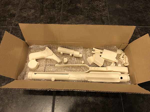
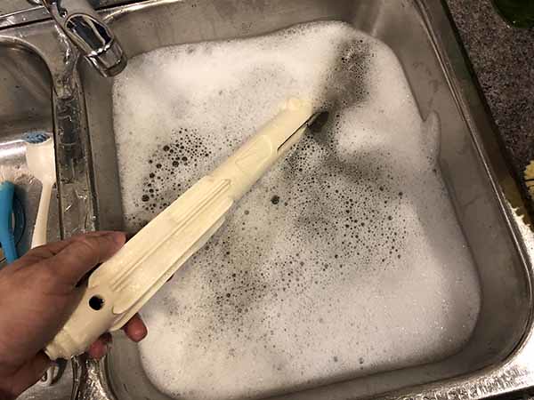
Can someone let me know if the photo's worked? It's my first time using Flickr to post embedded photos.
Thanks,
Mark
-
1
-
-
Merry Christmas and/or Happy Holidays, Everyone!!!
-
3
-
-
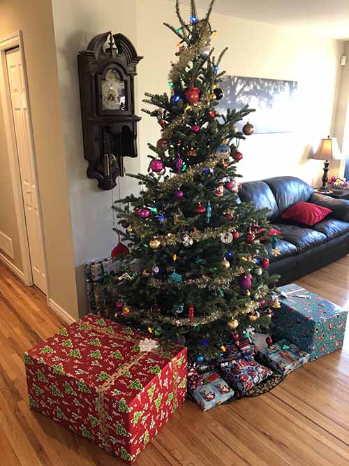
Ok, so it's Friday, three days before Christmas, and I'm jumping up and down like a school girl yelling:
OMG, OMG, OMG, OMG!!!!!
Santa came a few days early this year!!!
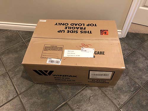
Now I'm going to summon up ALL of my strength....I will NOT open the box.
I'm wrapping it and putting it under the Christmas Tree. My daughter (age 6) will just have to deal with the fact that Daddy's Present from Santa is bigger than hers.

Mark
-
5
-
-
Thats PERFECT. Thanks, guys!!!
-
Hey guys, I'm just about to start a Doopydoo's/T-Jay build and I can't seem to find any reference photos of the bottom of the actual magazine clip. Does anyone have any images showing the detail on the bottom of the clip? Specifically the location of the round button and the lettering "OFF" and arrow?
Thanks,
Mark
-
Check out what I found at my local grocery store!! What better way to start off the journey of becoming a trooper? :-)
P.S. - Amazon has them too.
-
1
-

Wook's First Build - ANH Stunt TK (AP)
in ANH Build Threads
Posted
Thanks, Greg. A summary post of tips sounds great. I look forward to it.
Mark