Skippy
-
Posts
22 -
Joined
-
Last visited
Content Type
Profiles
Forums
Gallery
Articles
Everything posted by Skippy
-
Can you please change my name FROM SaluteToChickens TO Skippy Im trying to get all my forum names the same. Thanks!
-
I tried E6000 as well and it did not work at all. I use regular SuperGlue and it worked perfectly. I have even ran my gloves through the washing machine and the hand plates are still perfectly attached. Sent from my iPhone using Tapatalk
-
Thanks Ukswrath. You where part of my inspiration to do this project.
-
I wanted to pimp out my Anovos bucket and add all the bells and whistles. It is a space helmet after all. I added adjustable fans, hearing assist and room for upgrades all while keeping everything contained within the bucket and on 1 battery. After months of experimenting, and trial & error, this is where I ended up. General Mods First I painted the inside of my helmet with black truck bed liner. I used that to help add a little rigidity to the bucket, its textured so things will adhere to it better, and it looks cool. I ended up using a hardhat helmet liner. I tried the tactical helmet pads, but it just didn't work for me. The hardhat solution is perfect. I took out the lens and cut them to shape. I then got Tee Nuts from home Depot, bent down the sharp bits and glued them to the inside of the bucket. I could then use screws to attach the lens. To keep the helmet exactly where it needs to be on my head and stop the bobble-head look that some troopers have, I cut the nose bridge off of a pair of dollar store safety glasses and glued them to my TK lenses. All the helmet weight is on my head, the nose bridge just keeps my head locked in place. Electronics Here are the overall components and schematic. Here are the schematics. I will explain each part bellow. The blue lines show each of the different components. Battery This is a 12 volt (12.5 actually, 2A, 3500mAh) battery that I got from Amazon.com used to power string lights, (https://www.amazon.com/gp/product/B007RQW5WG/ref=oh_aui_detailpage_o04_s00?ie=UTF8&psc=1) I got it because its small, relatively light, but most importantly is has 3 cells in it. I realized that I was able to tap into each cell individually to get different voltages from it. I’m able to get 12.5 volts, 8 volts and 4 volts with a common ground. This was an amazing discovery, because I was playing with different voltage regulators, but they are bulky inside the helmet and create heat. Also opening the enclosure and using just the battery shrank the size of the battery. Inside the battery enclosure was a printed circuit board used to charge the battery. The circuit board monitors all 3 cells as it charges, so I had to cut the 4 connections, and install a 4 pin connector. So instead of the circuit board attaching directly to the battery cells, it goes though the connector first. You don't need the circuit board to use the battery, only charge it. It just so happened that the leads off the battery are 12.5v, 8v, 4v and a common ground. Perfect for what I need! To charge the battery I just attached it to this make shift adapter and use the provided wall transformer to charge it. Fans I wanted very quiet, but powerful fans. I found I was very limited at what was available with 5 volt fans. So I found these 12volt blower fans that where the size I wanted. (https://www.digikey.ca/products/en?keywords=bfb04512MD ). They where on the expensive side at $20 each, but they were perfect for my needs. I placed them inside the helmet blowing up beside the mic tips as seen below. My chin sits comfortably between them. One of the reasons I put them there was in was a good place to mount them for vibration reduction. The more I can reduce the vibrations, the quieter they will be. I made small adapter plates (from scrap styrene) to be able to mount them inside the curved helmet. I purposely left one side open so it can wiggle and absorb some of the vibrations. I glued the adapter plates in the helmet, but used Velcro to attache the fans. This is partly for extra vibration reduction, but mostly to be able to easily take them out if they need servicing. Adjustable Voltage Regulator To control the fans I decided to make an adjustable voltage regulator in order to turn them down or off. I got all the parts to make my own at a surplus store for maybe $3. I used the following schematic, which is all over the Internet. You need a LM317 voltage reg, 0.1uF capacitor, 240 ohm resistor and a 5k pot. I later found out you and buy pre-made ones on ebay for $1.50. I ordered one just to test it out. It works just as good, but because it’s on a printed circuit board, it has a much larger footprint then the one I built. Two VERY IMPORTANT things to note about this regulator is: 1) At full power it works great, no issues. When it’s turned down, and lets say the fans are running at 30%, the LM317 will produce heat and it gets fairly warm (that power has to go somewhere). I bent out a heat sync and I mounted flush inside of my bucket as seen bellow (it's the silver sheet metal part). For the very rare occasions I turn down the fans, the heat sink will solve that problem. 2) One of the biggest problems people run into when using one battery to power fans and a hearing assist is electrical noise. You can hear the static and buzzing in the headphones caused by noise from the fans. A filter in the system can help fix that. I discovered that this voltage regulator acts as a filter and it solved that problem for me. Hearing Assist A didn't know if I would actually use it, but I decided to go for broke and install it anyways. This came with a lot of challenges, including electrical noise, RF interference and power issues. But I got it all figured. The basic board is a very nice project board that I got from amazon.com for $14 (and a backup form a surplus store for $12) (https://www.amazon.com/gp/product/B0006HJSLE/ref=oh_aui_detailpage_o09_s01?ie=UTF8&psc=1) The board takes about 2 ish hours to put together, it comes with great instructions and the full schematics which was super helpful when modifying it. The board runs at 4.5 volts, but it can take 5v no problem. However I get 4v or 8v off my battery. I decided to use the 8v with a step down to make sure the board always gets its 5v. To step down the voltage I soldered in a LM7805 voltage regulator. It creates a constant 5V, I then soldered connector wires to it. Similar to the Adjustable voltage Regulator, the LM7805 produces heat. However the hearing assist draws almost no current (I measured it, but forgot the number. Its something like 10mA) so heat didn't end up being an issue. Next was the hardest problem to solve, the RF noise. If you use a wired microphone, this is a non-issue for you. I wanted to use a wireless microphone from amazon.ca (https://www.amazon.ca/gp/product/B01DNJKUI6/ref=oh_aui_detailpage_o00_s01?ie=UTF8&psc=1). This wireless microphone gives off a signal that the receiver picks up. The hearing assist AND mic cables also liked to pick up a lot of noise from it, in the form of a loud hissing/buzzing. Using regular wire to extend the mics from the board wasn't an option. I tested several cables (shielded wire, twisted pairs, Shielded twisted pairs, etc) and I surprisingly found that regular XLR microphone cable worked the best by far. It picked up no noise, it was black and flexible (perfect for the inside of the bucket, because some of the other cables was really stiff), and cheap at $0.10/foot at the surplus store. The only annoying thing was the cable had a braded shield. It was annoying to cut wile not damaging the wires or drain wire (the cable that runs with the shield for grounding purposes). I also added a connector in the cable so I could swap out the mics. If you do this, make sure to not only connect the 2 leads, but the drain wires as well to help shield the system. I used JB wield as a strain relief for the mic cables at the board and on the mics, as pictured bellow. I now had to shield the board. I used 2” heat shrink around the circuit to protect the components from shorting. I then used some copper ribbon I got at the surplus store for $5 ish. I wrapped it like a gift and soldered it together. I also soldered the two drain wires from the mic cables and the common ground from the power to the copper shield. This may have been overkill, but it works. I then wrapped the whole thing in another layer of heat shrink just to protect it all. RF interference is now a thing of the past. During my experiments, I damaged the mics that came with the kit, so I had to order a new set. I ordered 5 different types, just to try them all and experiment with them. The biggest obstacle here was all these mics are grounded to the negative lead. I wanted an independent ground to help with RF noise. Some mics you were able to scratch off the ground jumper with a knife and solder onto that. I ended up liking these noise canceling mics the best, but I will need to experiment with others at different troops. https://www.digikey.ca/product-detail/en/cui-inc/CMP-5247TF-K/102-1729-ND/1869989 To mount the mics, I did what everyone else does. I took the ear caps off the helmet and drilled a hole behind them. I drilled tiny holes in the ear cap so when replaced the sound can go it. After a fresh coat of paint, you don't see the tiny holes. To mount the actual mics, I used rubber grommets. This made it so I can easily swap out the mics, and the grommet act as a shock absorbent and dampener. So when someone taps your helmet, you don't hear it in the mics as much. To hear things, the headphones work but there is room for improvement. I tried using small speakers (from an old ski helmet) inside the helmet instead of headphones, but they just produce feedback. For now I have these $17 headphones (https://www.amazon.com/gp/product/B00V0JYQ50/ref=oh_aui_detailpage_o09_s04?ie=UTF8&psc=1). To pull in the headphone cable once the helmet is on, I attached the wire to a $5 retractable badge holder (https://www.amazon.com/gp/product/B01G1EY1Q2/ref=oh_aui_detailpage_o00_s00?ie=UTF8&psc=1). Once the helmet is on, it’s comfortable. This system works, but hopefully I can find a better alternative to these headphones eventually. Battery Indicator I wanted to put a battery indicator in the helmet to keep an eye on the battery. I came up with 2 easy solutions. Option 1: at $14 its the more accurate solution. (https://www.amazon.com/gp/product/B01LQ7MT4K/ref=oh_aui_detailpage_o00_s00?ie=UTF8&psc=1) It gives a very accurate reading, however it's a little on the large size, and its always on. I epoxied a switch to it so I can turn it off so it doesn’t light up the inside of my bucket when I am wearing it. Option 2: is $16 but better for what I need. (https://www.amazon.com/gp/product/B01E0U0JW4/ref=oh_aui_detailpage_o00_s00?ie=UTF8&psc=1). This indicator isn’t made for this type of battery, so there is a roughly 15% error on its read out. However, its small, waterproof, and when activated it only stays on for 30 seconds before turning off. As long as I am aware for the 15% error, it’s not a huge issue for me. For testing I use option 1, but I have option 2 installed inside the bucket. Note: You attach the indicators to the 12V on the battery. System as a whole This may seem like a lot of stuff, but I got it all to comfortably fit inside the helmet. I’ve ran a few tests and troops since installing it and it all works great. I’ve ran the whole system for 10+ hours straight (with different fan speeds) to see how long the battery would last for. I got bored and stopped the test after a little over 10 hour mark, so I know it will run for at least that long. I didn't weigh the helmet before, but it now only weights 2.4lbs with everything installed. I also made sure to balance the helmet when installing everything. The battery is mounted about 1 inch off center to help balance it on my head. I used connectors on every component, and Velcro with a little hot glue to install them. So if anything needs to be serviced or upgraded, its all removable. I used a large switch for master power switch, and mounted it where I could easily reach it while fully suited up incase of an emergency.
-

Celebration Art Show Exclusive Stormtrooper Equipment Print
Skippy replied to mr_sparkle's topic in Off Topic
Pre-ordered mine yesterday as well. It's an awesome design. Just out of curiosity, what made you go with the R1 TK as apose to the OT? Sent from my iPhone using Tapatalk -
My kit is done and approved, but after a troop I think it would be a little more comfortable if I cut out a small bit out of the thigh behind the knee. I know its been done, but I can't seem to find anything on it. Has anyone done this?
-
After just a few hours I got this up and running! Its an amazing project, thanks for making it so straight forward lerxstrulz . I wont be able to install it on my TK for a few weeks, but this is my set up so far. I opened my Aker MR1505 and tapped into its battery. That battery runs at roughly 8V so I had to step it down using a LM7805. There was just enough spare room iniside the Aker enclosure that I was able to do it. I then ran power to the 5V and Ground pin (it works great, but from the best I can see, if I run power to it AND plug in the USB into my computer at the same time I will have a problem. So its and either or thing). I put about 1.5 inches of wire on all the connectors so once I find an enclosure for it I can have just the wires stick out with a small hole. I also just ordered a few cheap Micro SD cards so I can have a few different profiles available to troop in based upon the type of troop (with and without a background loop, or different inputs for wireless or wired mic).
-
I'm just starting this project and I had an idea. Instead of having another battery, could you not tap into the Aker speaker battery? That battery is rated at 7.5 volts, but if you add a small voltage regulator to dump it down, it should work. Especially since the current draw is so low on the Teensy. That would save space and it would be one less battery to worry about. I just ordered everything I need and I should hopefully have this built in the next few weeks. Also lerxstrulz thanks for putting these tutorials and code together. I was looking for a way of doing this for a while, until I stumbled upon your thread.
-
Requesting Detachment Access TK-78383 http://www.501st.com/members/displaymemberdetails.php?userID=22846 Thanks!
-
Thanks guys! Yeah, that pain in the an impolite person logo is on my to-do list. @allan1313 I mostly used 2 inch elastic. I made temporary nylon straps that I can adjust the length of to connect the front and the back at the shoulders just to get the fit right.
-
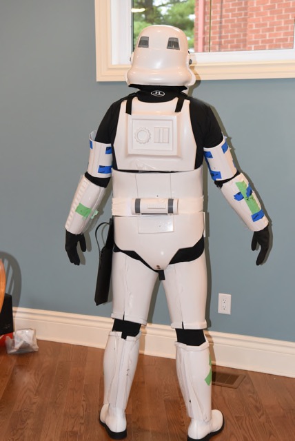
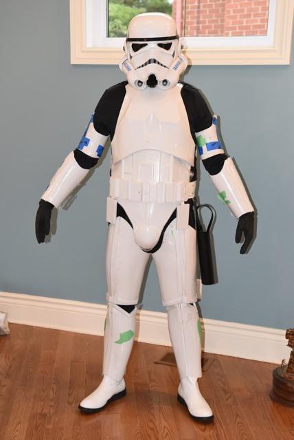
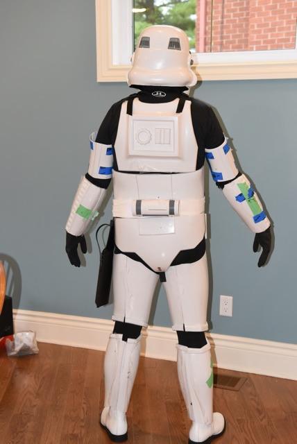
Excited to finally be at this point! Just did my first full test fit (minus the shoulder bells). Hows it looking to everyone fit wise?
-
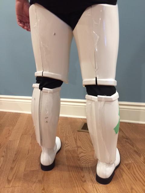
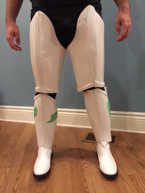
I just finished putting together my lower half (minus the cover strips, sniper plate and ammo) and I was just trying to figure out the fit. I cant bend my legs at all. I was planning on cutting out the back of the knee a little, but how does the rest fit? I think I should maybe trim the thighs, but I wanted to check here first.