

Coloursergeant
-
Posts
68 -
Joined
-
Last visited
Content Type
Profiles
Forums
Gallery
Articles
Media Demo
Posts posted by Coloursergeant
-
-
Looks like a great job, and a fun time for all!
Sent from my iPhone using Tapatalk
-
 1
1
-
-
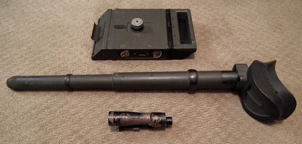
Just as an interesting comparison, here is a photo of some WWII tank scopes from my collection.
The long one is the actual gunner's sighting telescope. It is a model M70-F dated 1943 and is from an M4 Sherman armed with a 75mm gun. You can see how much larger it is than the 1943 dated M38 telescope next to it.
Behind them is a standard M6 periscope, which is the same size as the M4 periscope that the M38 was originally installed inside of.
-
3
-
-
Great looking blaster! I love seeing the real thing.
Did you make that stand?
Sent from my iPhone using Tapatalk
-
Great work on this project so far! I'm loving the whole idea of making everything from scratch.
I've never seen a hand punch that could punch metal like that before, I'm going to have to try to find one to add to my tool kit!

-
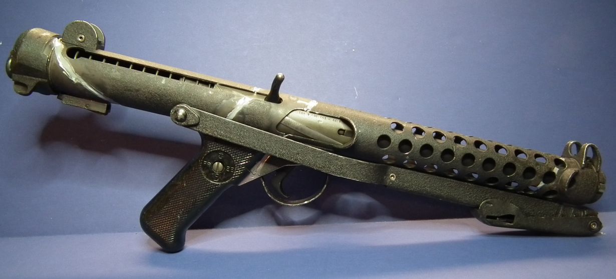
Here is my just completed Sterling ANH E-11
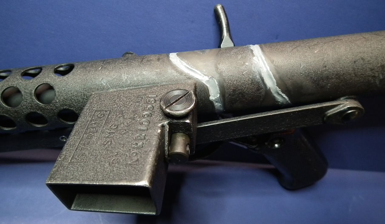
1968 Sterling SMG (demilled)
Real Hengstler 890
Aluminum M38 Replica (fieldmarshall)
Metal Power Cylinders (fieldmarshall)
Gino's T-Track
-
1
-
-
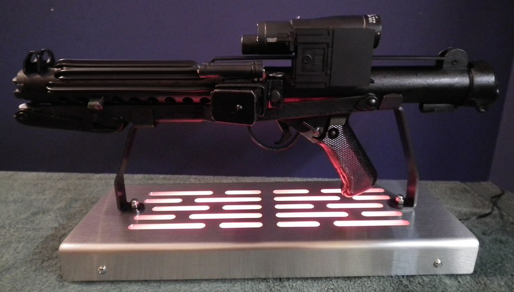
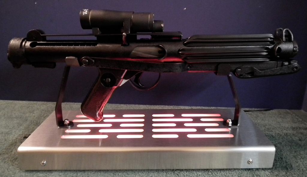
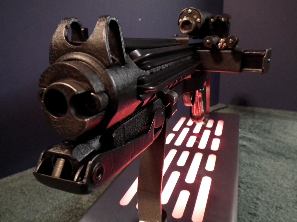
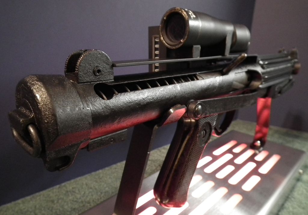
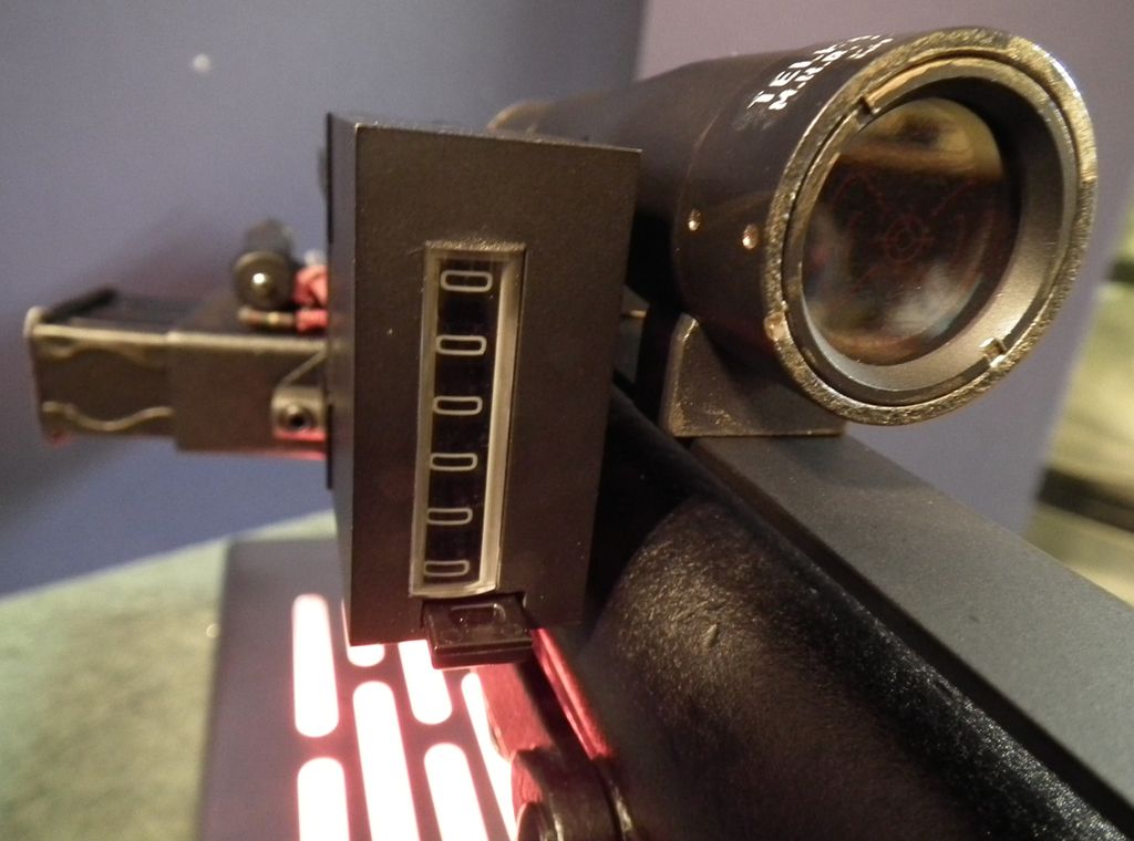
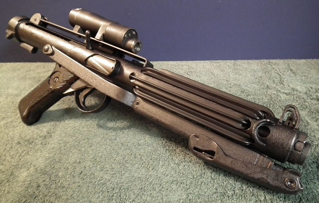
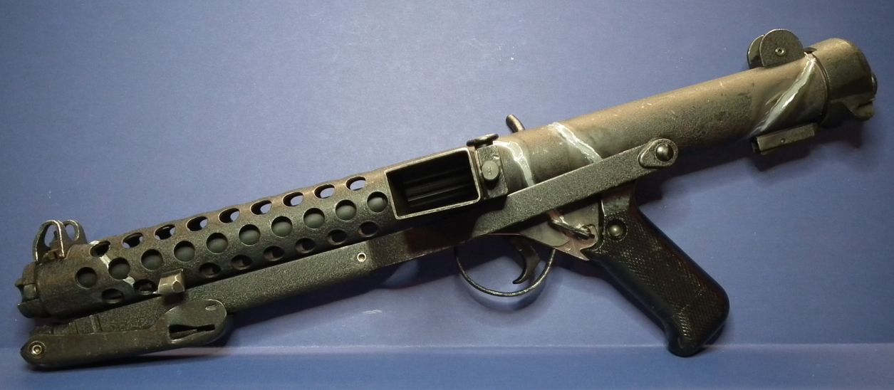
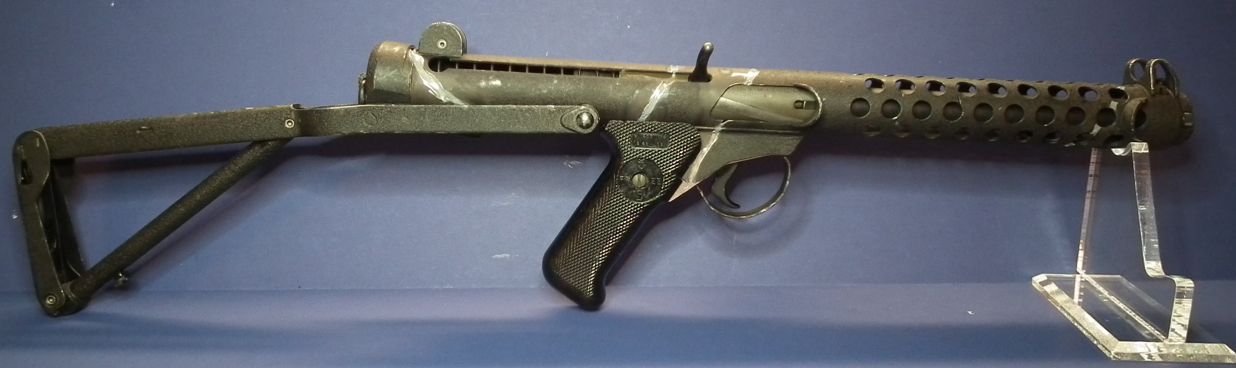
Okay, I have reached a point where I can call it finished! (at least for now anyway)

It's far from perfect, but I am VERY happy with it! Here are some pics.
I'm also really pleased with the stand I found for it. It has a remote control, lots of different light colors, and various lighting effects. Best part is it holds this heavy beast most solidly!
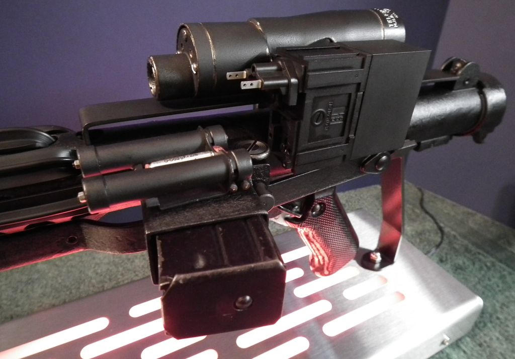
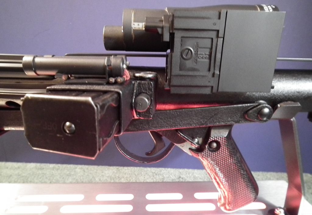
Another thank you to Chris (Fieldmarshall) for the M38 scope and the power cylinders. I left the resistors and the red cloth wire covers unpainted, I only dry-brushed them some to dirty them up just a little. They are just too nice to cover up and I also wanted to leave little bits unpainted here and there to show the various materials, colors and textures.
My T-Tracks didn't come out too bad, but next time I hope to do better.
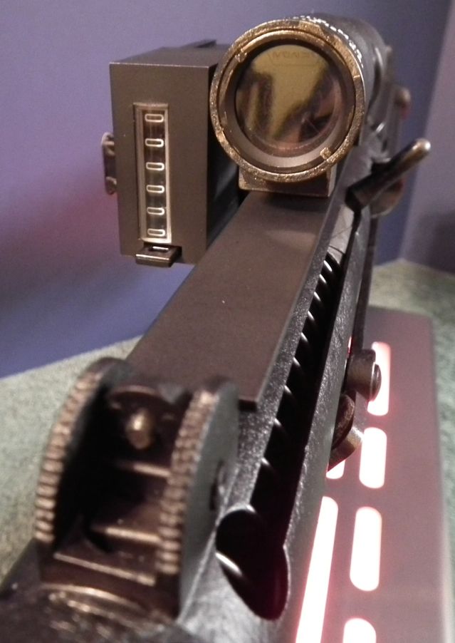
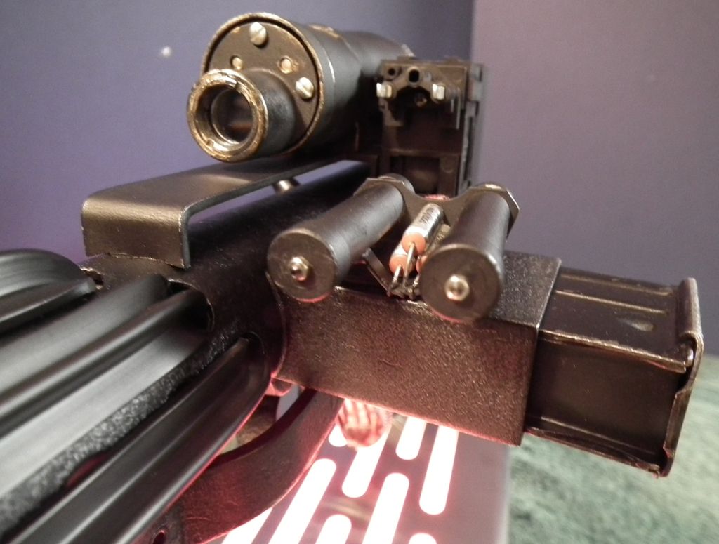
I love this view of the business end!


Once I get my TK number, I'll set it on the Hengstler and block the reset button internally to lock it in place.
I'm sure once I've had a little break, I'll come back to this and tinker with it some more, but right now I just want to enjoy it for a while.
Oh, and the final weight completely assembled??? 7 lbs 12.2 oz (3.52 kg)!!!
This baby packs quite a heft!
Thanks to everyone who helped on this by providing parts, helpful advice and instruction, or who just followed along. Hopefully something here will help or inspire someone else someday.
-
2
-
-
I keep coming back and watching this over again. I hope you end up making another!
Oh, and I shared it on Facebook for you!
-
1
-
-
This is a pretty cool project. I didn't think you could really do this type of modification with the material the Hyperfirms were made of, but you've proven it!
I'll keep following along, I may have to get one of these now.
-
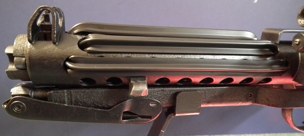
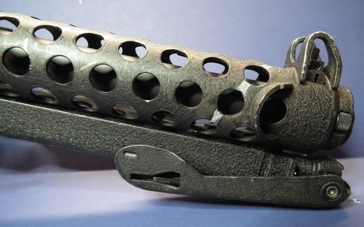
Great update, Jon. Another good thing on the little wider T-tracks from Roy is the fact, that the venting holes in the receiver tube are being fully covered. With thinner tracks it can end up like this:
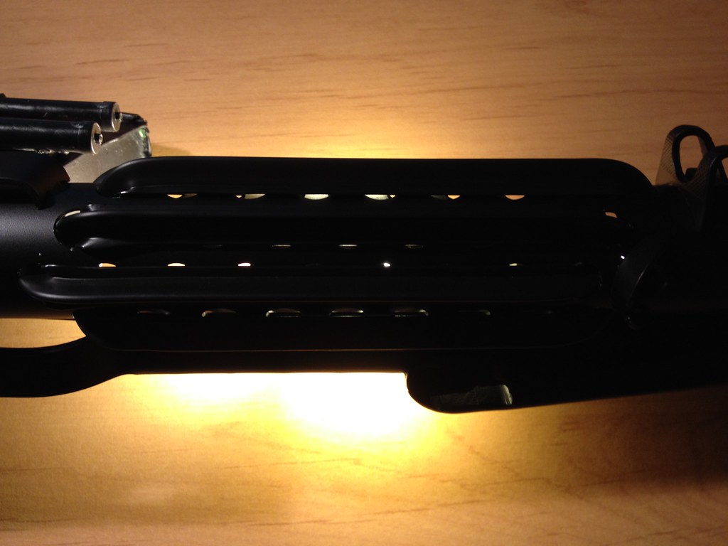
And thanks for mentioning the T-track tutorial. Glad if it was (or will be) of any help. When do we get to see pictures of your finished tracks?

Good point about the wider tracks Tino.
I am gluing down my tracks with E6000 to keep them tightly in place. The steel blaster is so heavy that I felt it put too much pressure on the tracks while handling it. Right now everything is clamped in place while drying.
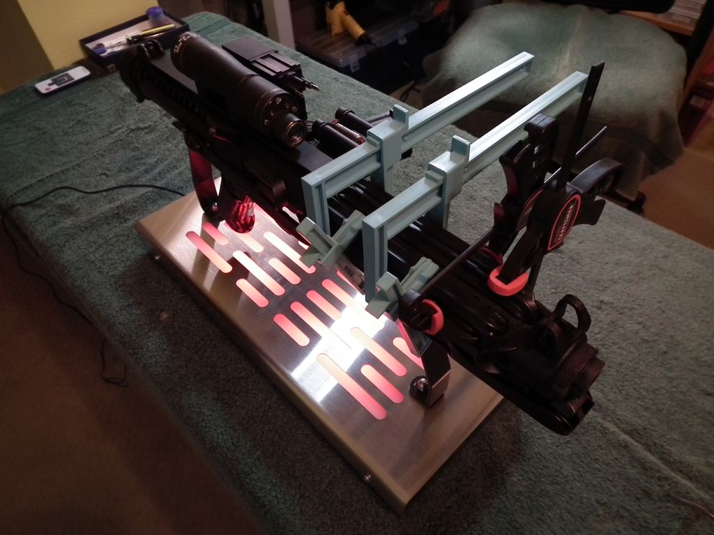
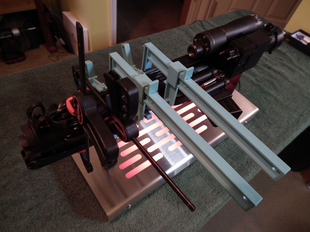
These pics also give a little preview of the awesome blaster stand I picked up from Canadian seller QuestDesign on eBay. It is strong enough to handle the weight of the steel blaster, and the color-changing lighting effects it has are really cool! It even has a remote control for operating the lights.
I ended up using Scotch 414 "Extremely Strong" double sided mounting tape to install my power cells. They claim the tape will hold up to 30 lbs and it's already black so it blends right in. It comes in one inch width, which is perfect for the power cells. It seems to be holding the cells very securely and is not visible at all, so I'm pretty happy with that.
-
1
-
-
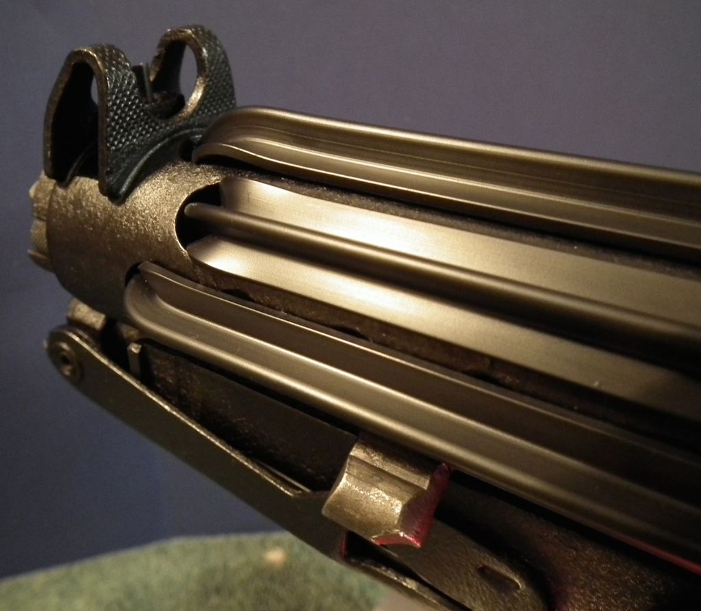
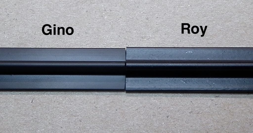
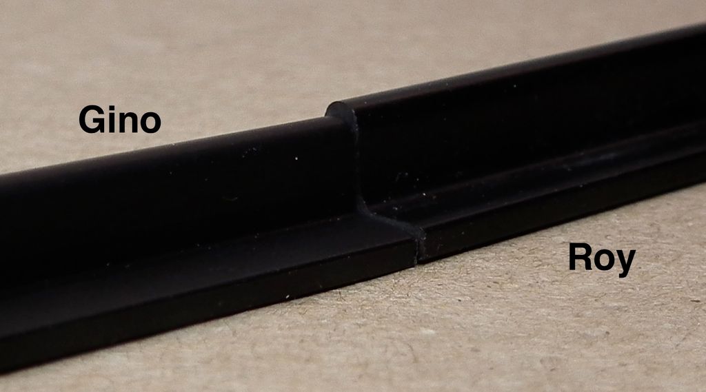
I had mentioned earlier in this thread that I had ordered T-Track from both Gino on TheRPF and Roy at wannawanga to compare them. I have both sets in hand now, so I thought I would post some comparison pics.
Here are the two side by side. You can see that they both seem to have the correct shape when compared to images of original film used track over on the e-11blaster website.
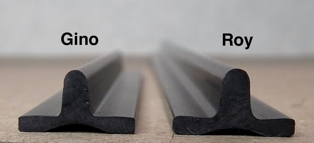
Roy's just seems to be a little bit larger in all dimensions than Gino's.
At half the price Roy's is a pretty good deal, but I think that I like Gino's the best (IMHO) and that is what I used on this project. Gino also provided an extra two inches to the length of material supplied (10" vs 8" from Roy) and I really appreciated the extra material, as I had some errors while getting the hang of heating and bending the track that had to be cut off an discarded. If I hadn't had the extra long material I may not have been able to complete the job.
With that said I would still say that Roy's is a good choice, especially when cost is a consideration. And as Tino (T-Jay) pointed out, Roy's wider track could do a better job of covering the vent holes in the tube. I will certainly be using the track I bought from Roy on my next project.
As far as I know these are the only two current sources for correctly shaped T-Track.
-
1
-
-
Wow, this worked very well. I was indeed curious to see how you bring that pattern only to the repaired spots. Well done!

Thanks Tino!
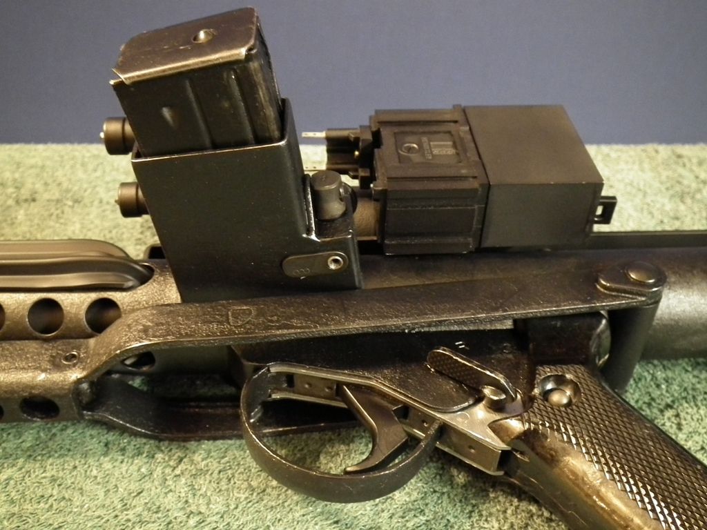
After working so hard to preserve the original finish, every time I mocked up the blaster with the prop add-ons (Scope, Hengstler, etc.) it just didn't look quite right. After a while I realized that the original finish had too much grey in it. It wasn't black enough to mesh well with the black add-on parts.
So I took what felt to me like a huge risk, and I shot the whole body of the Sterling with satin black (okay, I actually had one too many beers that night and decided to take it outside and paint it in the dark!). Immediately after painting it, I thought "what a disaster", I just hung it up to dry and left it until the next day (i.e. passed out) I still wasn't feeling very good about it the next day (hungover), but once I started assembling it and installing the greeblies, all of a sudden it felt like I was looking at a real E-11! Assembled the deeper black color made a huge difference and now the greeblies look like they belong, and everything meshes together like it should. I couldn't be happier.
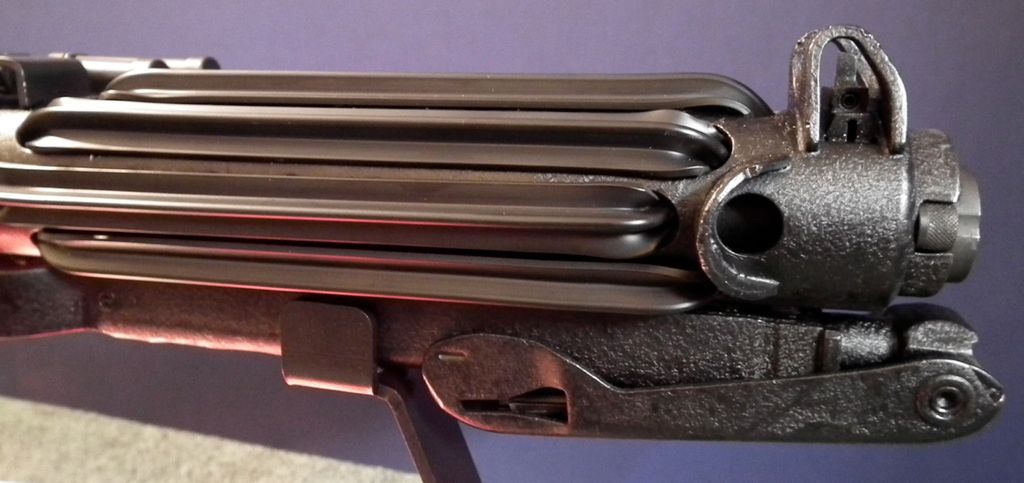
I did leave the nose cap unpainted to preserve one bit of the original finish. It just appears to have been slightly oxidized from the "energy bolts" it has fired in combat!
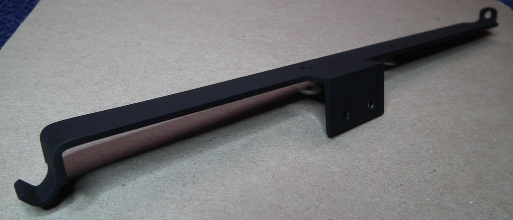
I have also finished reworking the scope mount so that it fits properly, and is level. I curled the front tab around enough that when installed it presses up against the inside of the Sterling tube to hold the front quite snugly in place. I also drilled and tapped the 200 Meter peep sight opening on the Sterling for a 6-32 screw thread, and I am using a blackened button head hex screw to attach the rear of the scope mount to the sight.
For smooth metal parts like this, I paint them with flat black and then after the paint has dried for a day, I rub it down with gun oil and an old tee-shirt (I use Break Free CLP gun oil). This smooths out the matt surface and leaves it looking more like a Military black oxide finish. In the first pic below, the paint is still matt black and hasn't been rubbed with gun oil yet.
I also found some blackened button head 4-40 hex screws for attaching my Hengstler. Much better than the painted phillips head screws I had at first!
I have also started working on the T-Tracks. Here I have to shout-out another big thank you to Tino for his excellent tutorial on this subject, I would have been completely lost without it!
I used some of my leftover copper pipe to make a jig for making the first bend in each track. Since my Sterling has been "permanently" assembled, I cannot get inside the outer tube very well, and my PVC inner barrel is slightly oversized which limits the available space even more. This jig allows me to press up on the T-Track inside the tube while it cools, using a gloved finger of course!
I'm getting close to the end on this project now. All that really remains is the final installation of the T-Tracks and gluing the power cell assembly in place. I must confess that I am nervous about the final T-Track bends. It seems like a lot has to be done very quickly to get the track in place before the plastic cools.
Does anyone have any suggestions on what adhesive to use for attaching the power cells? Has anyone used E-6000 on a metal to metal joint like that?
-
1
-
-
Howdy from Everglades Squad!
Hi Ben,
Your the first person I've "met" from the Everglades Squad!
With a little luck I'll meet you in person at a troop someday.
I'll get on the the local boards once I have my BBB Day.
Jon
-
Thanks everyone for the warm welcome!
-
From what I've gathered so far, all the available Sterling parts kits people are getting come damaged from drilling. Is this correct or not?
I've seen some pretty messed up parts kits out there. Most of the stuff on Gunbroker is pretty bad, and over-priced. But the set I recently purchased from Numrich Gun Parts Corp was pretty nice.
You can see photos of in my build thread here: http://www.whitearmor.net/forum/topic/38788-coloursergeants-steel-e-11-blaster-build/
The tube was torch cut in four places, but the cuts where small and neatly done. There were no missing parts and nothing was "drilled" as you mentioned in your inquiry.
I elected to buy the version with the demilled barrel, so the barrel was saw cut at the front and back, making it three pieces. But they offer a kit with an intact barrel if that's what you want, it just costs a lot more.
The kits don't come with magazines, but they have them on offer too, and the one I received was very nice.
If you are in the US, then this would be a pretty good choice.
I hope this helps.
Good luck!
-
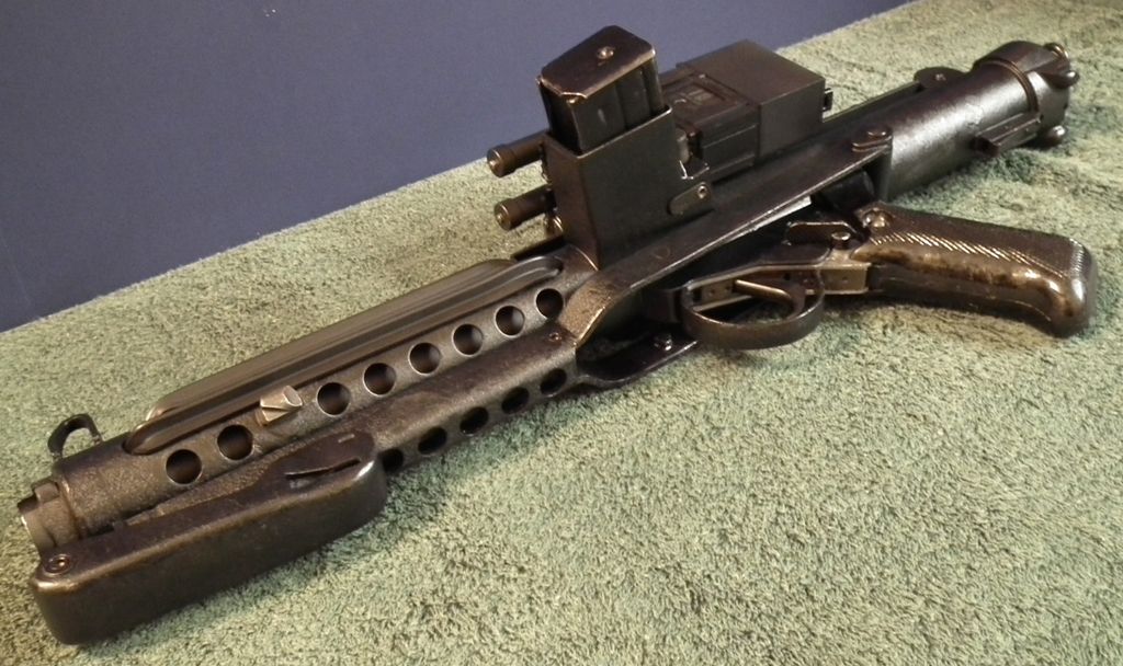
Okay, so finally the basic Sterling is finished!
I finished filling the gaps using epoxy ribbon putty which worked out pretty well. Once the filling and shaping was done, I brushed on some Humbrol matt black to help me see where I still needed to smooth out the seams. When I did that, I was surprised to see how well the matt black blended into the rest of the original finish, it just needed some more texture. I experimented with dabbing the paint with an old brush and that did add some texture, but not enough. Next I picked up some Rustoleum textured black spray paint. I spayed this into a cup and then painted it on with a brush. It still gave the needed texture without having to mask and allowed me to blend the paint more subtly into the surrounding areas. I then went over top of that with the humbrol matt black again to match the color of the original finish.
My goal has always been to preserve as much of the original finish as possible, so this allowed me to accomplish that.
Here's how it came out. It could be improved but I think it's good enough for now, and I'm anxious to get on with converting the Sterling into an E-11.
Next I need to work on the scope mount bracket that I purchased. It doesn't fit quite right and is going to need some modification.
-
2
-
-
I thought it was time I should make a newbie post to introduce myself. I actually joined the forum a year ago and was planning on moving forward with my armor purchase at that time, but as often happens life got in the way for a while. Buy I am happy to say that I am getting very close to my Big Brown Box Day from RS Prop Masters!
This has been a life-long dream for me, I had just turned 14 years old when I sat in the movie theater that day in May 1977 and watched an Imperial Star Destroyer roar out of the top of the screen, and I knew at that moment that the world had changed forever! And as soon as I saw those troopers in white armor fight their way into the Rebel Blockade Runner, I new what I wanted to be... Fast forward some 39 years and that day is about to come true!
Last year I picked up a WTF bucket built by TKittell on this forum (Thanks Robert!) and I have collected some other key items like an iComm unit and a set of helmet fans from UKSwrath.
Currently I am working on a Sterling based ANH E-11 build and I started a build thread for that here: http://www.whitearmor.net/forum/topic/38788-coloursergeants-steel-e-11-blaster-build/
I am looking forward very much to becoming a 501st member, and hopefully meeting some Everglades Squad members in the not too distant future.
I also want to say how amazed I am at the creativity and craftsmanship of so many of the members here. It's great to see how many members are willing to take the time to share their efforts and everything that they've learned along the way for the benefit of others.
-
Sean, Thanks for the link, this is EXACTLY what I was looking for! All of Tino's work is amazing. I don't know how I had not seen that particular thread before.
-
Thanks, Jon. It looks like you're gearing up for a nice sterling parts build yourself!
Yes, and I will certainly borrow from your painting/finishing methods to repair the crinkle finish on my Sterling!
-
Okay, I have a little more progress to report.
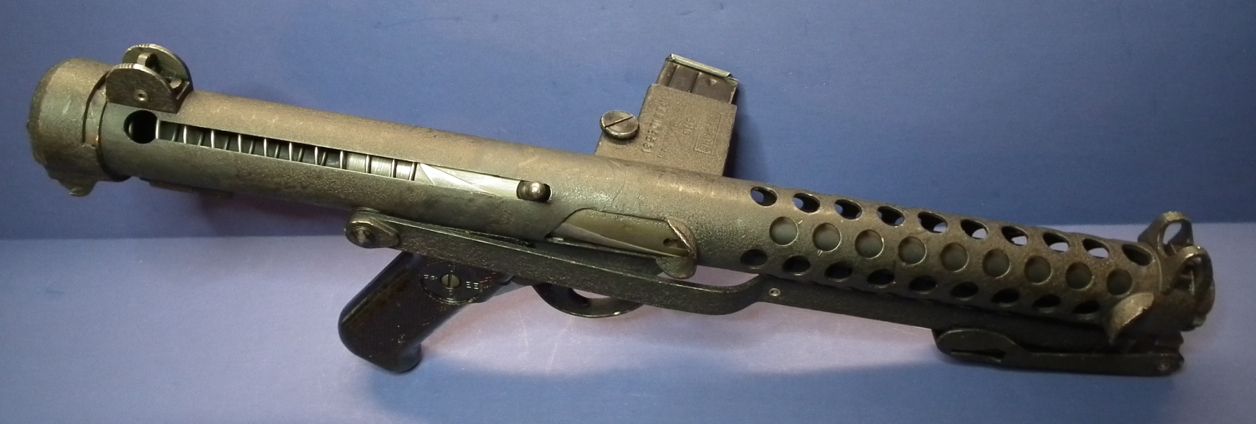
I have finished the structural reconstruction of the basic Sterling. Everything is fully bonded together and just needs cosmetic filling and finishing for the base gun to be complete. I was worried about the joint just behind the cocking handle as this had the least amount of structural support, but it turned out to be very solid.
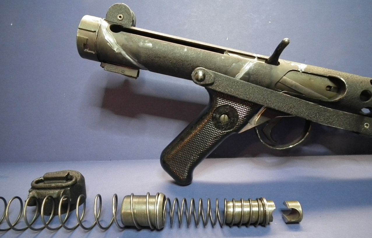
The stock unfolds and locks into place perfectly. The end cap works like it is supposed to and pushes in against the recoil spring to latch and release the open stock.

I used JB Weld to bond the pieces together. I left a little bit of a depression in the JB Weld at most of the seems. I will now go back and fill these in flush with some epoxy modeling putty, or some green stuff, which will be easier to work with than the JB Weld for the final surface.
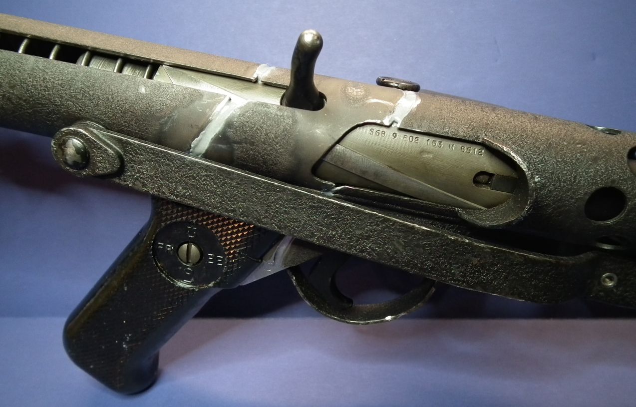
I had the trigger group installed while bonding the center sections together in order to help control the correct spacing, but I made sure that the trigger group did NOT get permanently attached, as I want to be able to remove it later on.
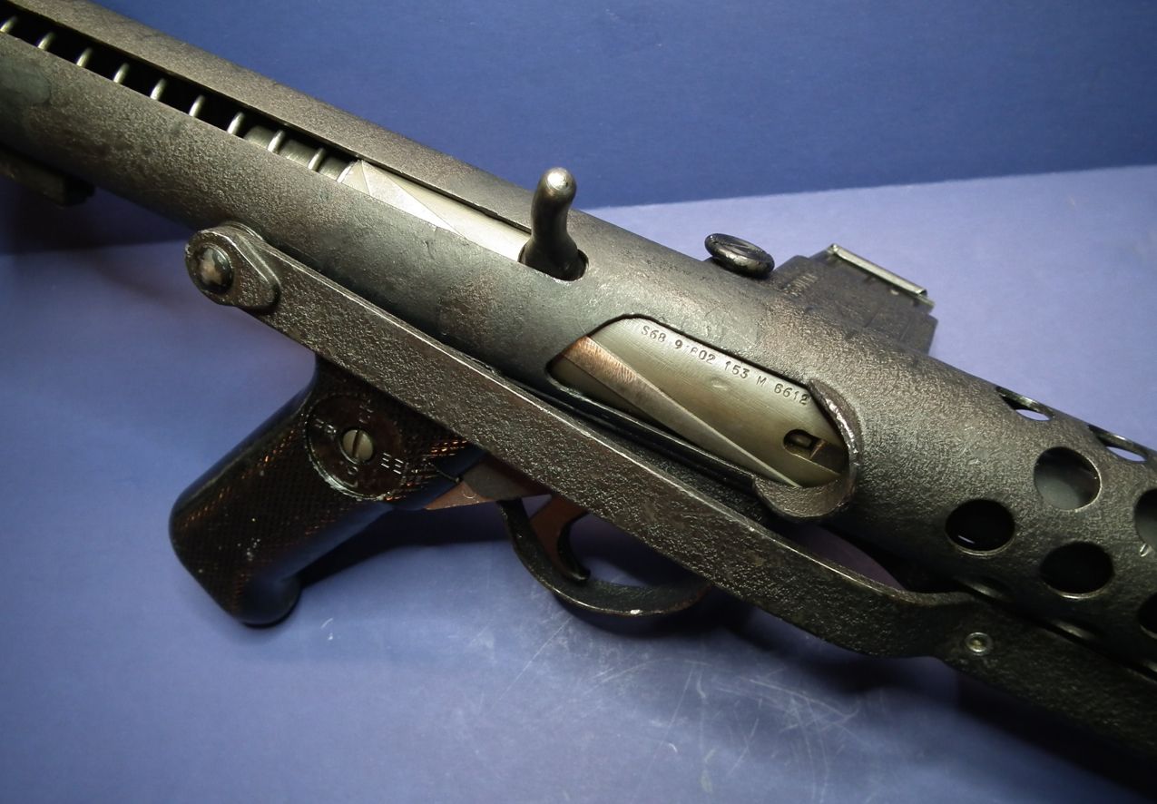
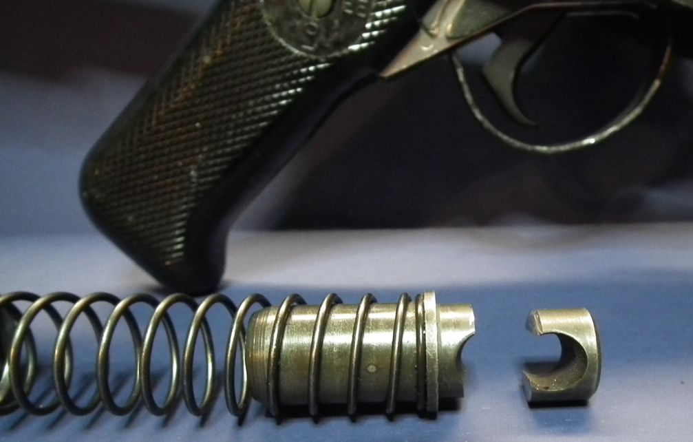
I also wanted to be able to remove the recoil spring after assembly, but as the bolt is permanently bonded in place and can't be removed, I didn't want the front of the spring trapped by the cocking handle which pins it into the bolt. To get around this I just cut off the front of the forward spring fitting that connects with the cocking handle so now the entire spring assembly can still be removed when desired, and you can see the correct 11 coils of the recoil spring when assembled.
Now that I have the assembled basic Sterling in hand, I can immediately feel just how heavy this thing is! I put it on my postal scale and it weighs 6 lbs and 5.8 oz without the magazine installed.
The specs I've seen say that the Sterling is only supposed to weigh 6 lbs 0 oz unloaded, so apparently my additions (copper pipe and JB Weld) have added a little extra weight even after replacing much of the original steel barrel with PVC pipe, cutting off the tip of the recoil spring fitting, and eliminating the sear parts.
The shortened magazine adds another 5.2 ounces.
If anyone else has a Sterling they can put on a scale I'd be interested to know what theirs weighs in at!
Can anyone recommend the best thread(s) to review for cutting, bending, and installing the T-tracks? I have a set of Gino's tracks in hand, and I'm waiting on a set from Roy at Wannawanga so I'll be using one of these sets.
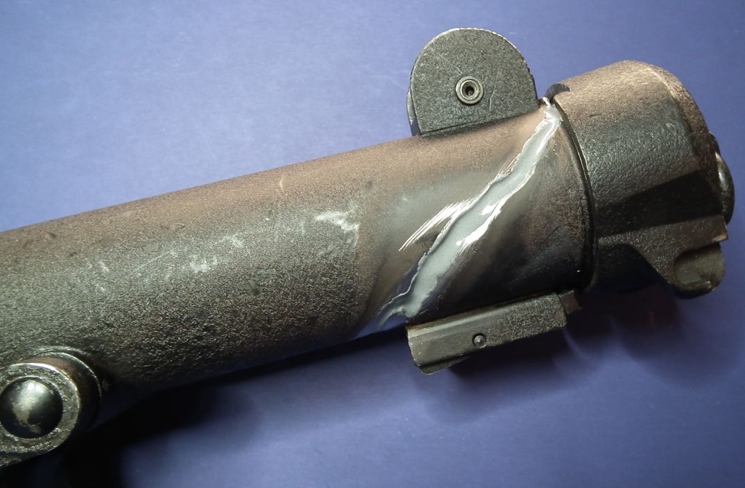
I would also welcome any suggestions for repairing the finish on the Sterling tube at the glued joints without refinishing the entire piece. You can see that the cutting torch burned away sections of the crinkle finish around the cuts. I really want to preserve as much of the original finish as possible.
-
That was Brilliant in all respects. Well done!
Sent from my iPhone using Tapatalk
-
1
-
-
Beautiful Build! I love the weathered and chipped crinkle finish! It looks just like the finish on my original Sterling parts, only even more weathered.
Fantastic job on the electronics/wiring too, that must have been a real challenge, but it came out amazing.
Well done!
-
Hi Jon, welcome to the white zone

That is a very interesting way to re-connect the pieces of the receiver tube. Did you drill the holes in the same diameter than the Sterling holes, or a bit bigger?
The channel for the charging handle seems to be a little wider. Well done, so it cannot be spotted immediately.
Hi T-Jay,
I did make the holes larger than the Sterling in order to hide them better, as you spotted on the charging handle slot. I had to be very careful though as the copper pipe is very soft metal and thin. As more holes were drilled in the pipe the easier it became to deform the copper. The drill bit would tend to grab the edges of the hole and could literally twist the surrounding area out of shape.
I ended up drilling the holes just large enough to fit in a ¼ inch Dremel sanding drum and then had to grid them larger from there. The copper pipe got VERY hot during this and gloves were required to hold the part during grinding.
I had to sand down the outside of the copper pipe insert so that it would fit smoother into the Sterling tube, as it was a very tight fit at first. This also helps leave a little room for JB Weld when fixing it in place.
-
Hi Jon,
welcome to the FISD! Great project you started! I will follow your work.
I love these blaster builds!Cheers
Christian
Hi Christian,
Thank you for the welcome!
I am really looking forward to becoming a 501st member and part of the FISD community.
-
I finally have an update to post. I have been making the parts I'm going to use to reconnect the cut-up tube pieces.
In order to put the tube back together in such a way that it looks intact, but is legally not a functioning firearm again, I am going to have the bolt fixed in place and internally blocked so that it cannot move. I am not going to weld the tube pieces back together, but I am going to epoxy the pieces together with internal splints or splices to help hold everything together rigidly. I am making the splints for the very front and rear cuts using pieces of 1¼" ID copper pipe. This pipe fits perfectly inside the Sterling tube and can be easily cut and drilled to match the outline of the Sterling parts. I used type M pipe which has the thinest walls.
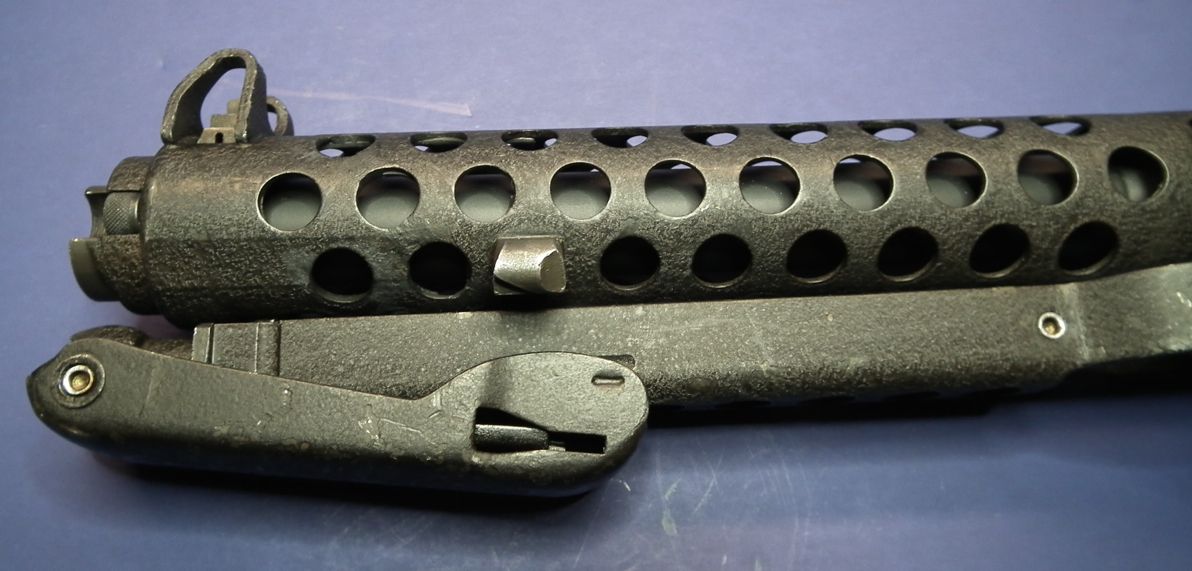
Here are some photos of the front splint I made:
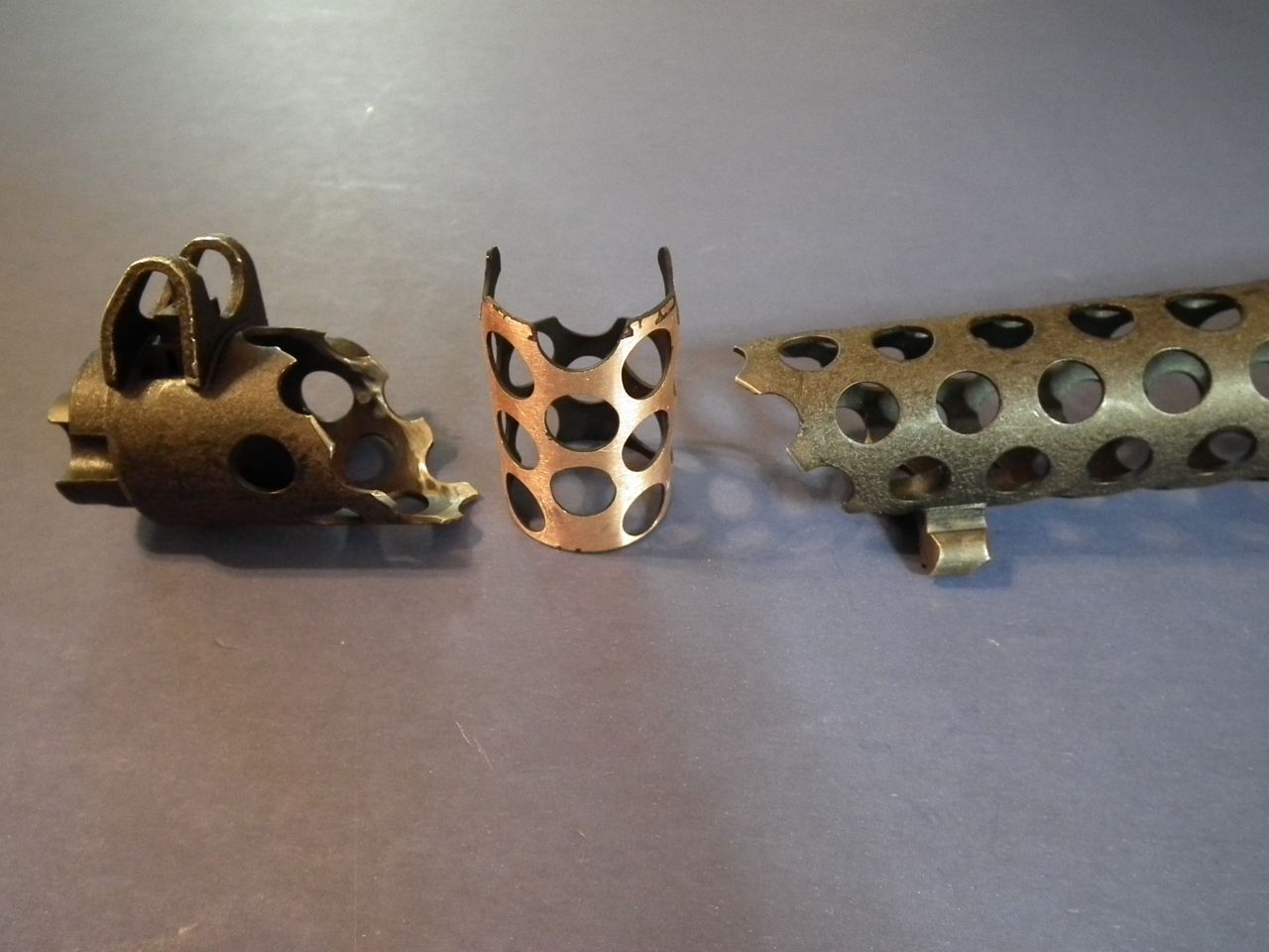
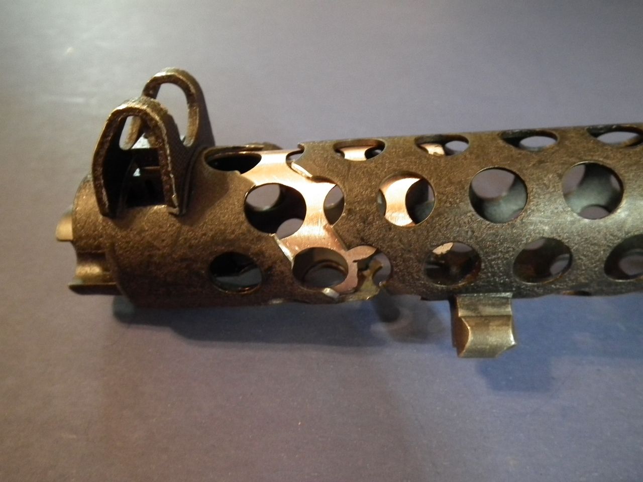
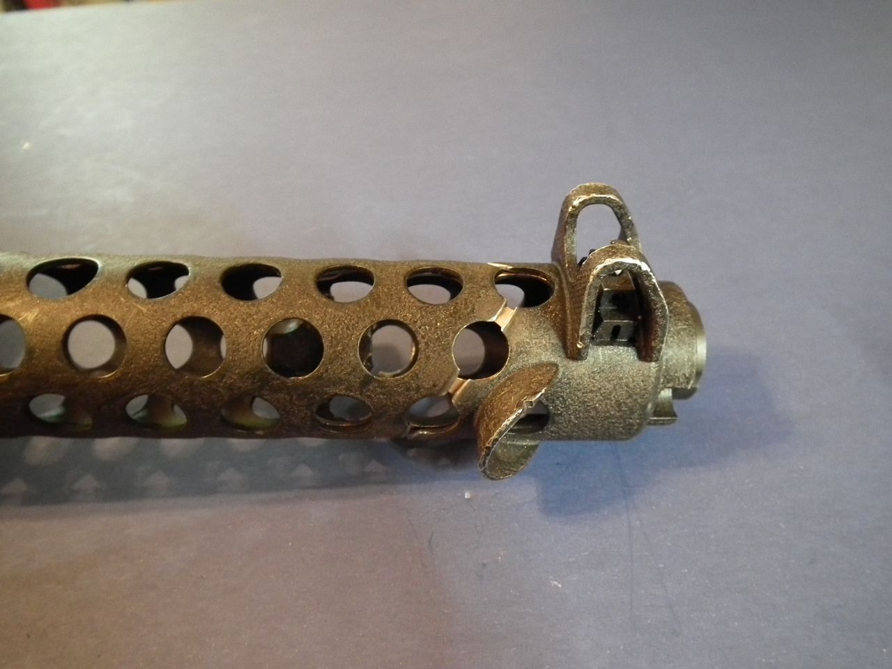
As you can see the splint pipe is completely hidden once fitted into place. I painted the inside of the pipe flat black. The next step will be to glue it in place with JB Weld epoxy.
I also made a pipe fitting for the rear cut in the Sterling receiver. This part I made long enough so that when installed it will extend right up to the rear of the bolt and will physically block the bolt from moving. The inside diameter of the copper pipe is large enough that I can still install the original Sterling spring when everything is ready for final assembly, so it will look perfectly normal.
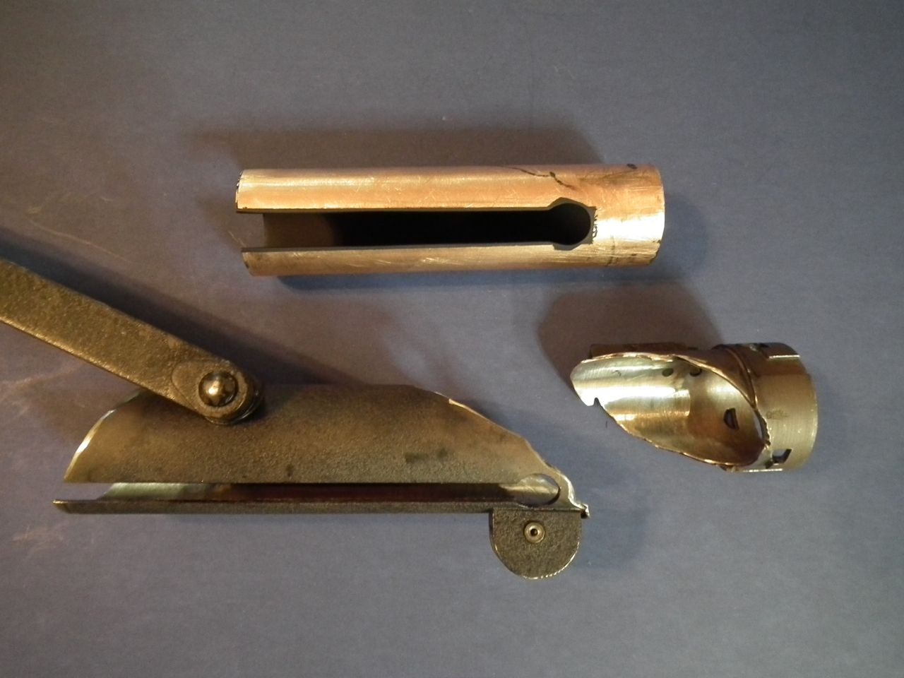
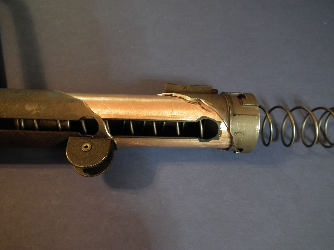
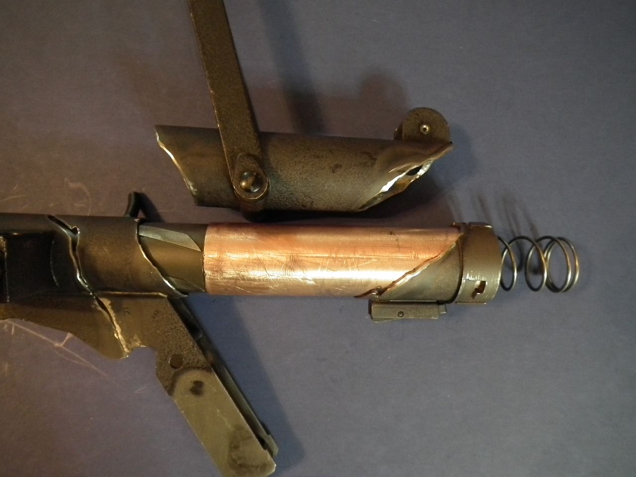
Because of the way the Sterling goes together, I am going to start at the front and work my way back as I JB Weld the cut Sterling tube back together again. I made the copper splints above for the front and rear cuts in the receiver, but the middle two cuts lay directly over the guns operating bolt, so I am going to use the bolt itself as the splint for these cuts and JB Weld it into place to hold the Sterling tube together.
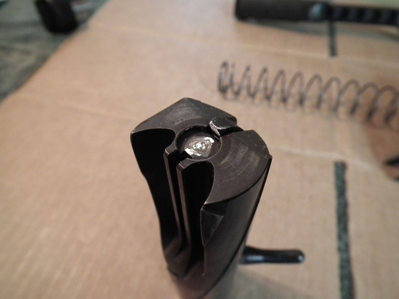
In preparation for this I used my Dremel to grind away the firing pin from the face of the bolt as shown in the image below. At the same time I cut away the hook from the extractor as well. These parts will not be visible when assembled, but little things like this go a long way towards making the folks over at ATFE happy, and I certainly want to avoid any "Imperial Entanglements"!
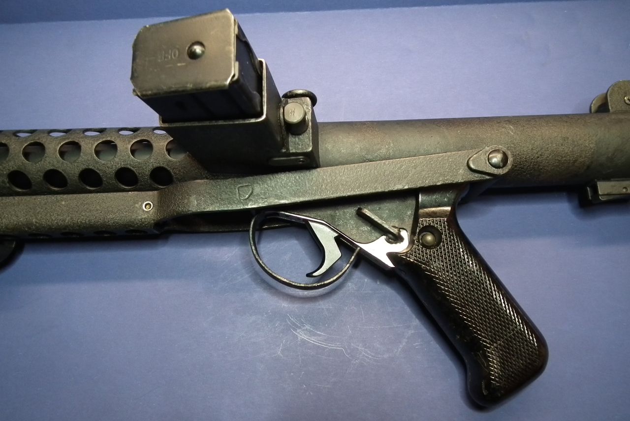
While I was thinking about compliance issues like this, I went ahead and removed the Sear and Tripping Lever from the trigger group (Below) and discarded those parts as well. The trigger and selector lever still operate and feel the same after removing these parts so nothing is lost by doing this.
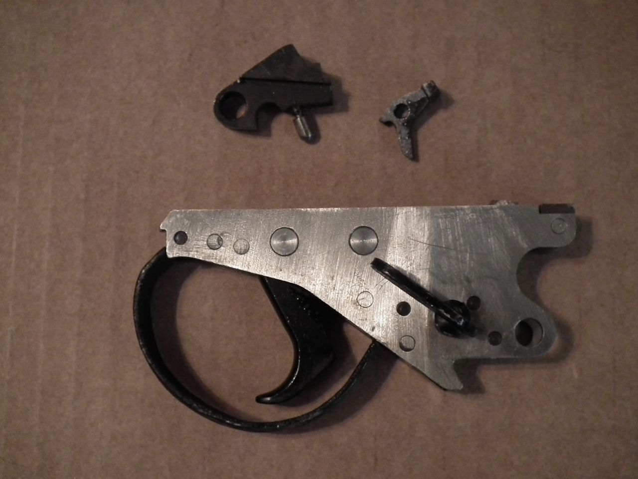
Now it's time to start putting the pieces together!
-
1
-
501st Trooper Status Requests (Include link to your 501st profile in your request!)
in 501st and Detachment Access Requests
Posted
TK-12513 requesting 501st access!
http://www.501st.com/members/displaymemberdetails.php?userID=22699