Ruthar
-
Posts
282 -
Joined
-
Last visited
Content Type
Profiles
Forums
Gallery
Articles
Everything posted by Ruthar
-
Additional Details First Order TK Belt Only a few more items left prior to painting! Next up, the belt. I picked up one of @JAFO's absolutely wonderful First Order belt kits, and I am very, very pleased that I did! I can't recommend his work enough. Not only is the quality of product great, his speed and service is equally amazing - from Australia to my NJ home in only a week's time! Truly awesome stuff. 1) The belt comes in three sections - an initial nylon layer followed by a thick sponge layer that is topped off with the final ribbed rubber layer. They all come detached from one another, so I started sizing with just the nylon belt alone. I wrapped it around the lower edge of the abdomen/kidney section to measure out the necessary size. One end of the nylon belt is already permanently attached to one half of a large parachute clip - the other side needs to be adjusted to the appropriate length and then slipped through the other matching side of the parachute clip. I taped the nylon to the armour to keep it up while I was looking at the fitment. Untitled by Taylor Goodson, on Flickr 2) Where the nylon belt looped through the parachute clip and back under itself, I put a piece of painter's tape to mark the total length of the nylon. Untitled by Taylor Goodson, on Flickr 3) On the painter's tape, I drew a pair of x's to mark where the first duo of chicago screws will be installed. These screws will hold the looped nylon around the parachute clip and keep our belt permanently held at the proper length. Untitled by Taylor Goodson, on Flickr 4) Using a soldering iron, I melted two holes just wide enough for the chicago screws through the nylon where marked with the painter's tape. Untitled by Taylor Goodson, on Flickr 5) Next is adding the sponge layer. I nestled the sponge material right against the parachute clip, then clamped it against the nylon tightly to keep it in place. Untitled by Taylor Goodson, on Flickr 6) Using the pair of holes we already made in the nylon as a guide, I pushed two holes through the sponge layer as well. Then, I attached the nylon and sponge layers together with a pair of chicago screws. Untitled by Taylor Goodson, on Flickr 7) I ran the sponge material between the parachute clips and cut off the excess. Then, I duplicated the process at the parachute clip at the other end of the belt with another pair of chicago screws holding the layers together. Untitled by Taylor Goodson, on Flickr 8) The final, third layer of the ribbed rubber was next. I cut the rubber belt to match the length of the previous two layers and then added holes here to use the same four chicago screws to hold this new additional layer as well. Untitled by Taylor Goodson, on Flickr 9) The pair of soft pouches on the right will hide the chicago screws running through the ends of the belt. To ensure that they don't slide along the belt, I use a couple safety pins to hold them in place. Untitled by Taylor Goodson, on Flickr 10) To give the belt a clean look, I glued an extra bit of the rubber material directly to the outside of the parachute clip. With this added, the small gap between the pouches reveals the rubber material just like the rest of the belt instead of the plastic parachute clip. Untitled by Taylor Goodson, on Flickr Untitled by Taylor Goodson, on Flickr 11) Next, I checked the fitment of the belt along the bottom edge of the abdomen once more. I held it in place with a couple clamps and lined up the front (smaller) pouch just beneath the first abdomen box. Untitled by Taylor Goodson, on Flickr 12) With the belt held in place, it's time to install the two front boxes. The center of the abdomen piece should line up right between these two boxes and there shouldn't be more than a half inch or so between them. Untitled by Taylor Goodson, on Flickr 13) When you are pleased with where they are sitting, remove the top of the long boxes. Drill two holes wide enough for chicago screws into the center of the bottoms of the long boxes. Then, mark the locations of the chicago screw holes on the belt itself. Untitled by Taylor Goodson, on Flickr 14) It might take a bit of effort, but make holes at the marks on the belt. Carefully fit chicago screws through all four layers (the nylon, sponge, rubber, and box plastic) and screw them down tightly. Once the backs are down firmly, temporarily place the fronts of the boxes back on to test how everything looks. Untitled by Taylor Goodson, on Flickr 15) Remove the fronts of the long boxes and the belt from the abdomen piece and set it aside for the time being. Untitled by Taylor Goodson, on Flickr 16) Before we can install the hard boxes on the right hip to the belt, they need to be glued together and painted. First is the thinner, front plastic box on the right hip. Run a bit of E6000 around the inside edge of the outer box. Untitled by Taylor Goodson, on Flickr 17) Slip the inner box within the outer box and allow the E6000 to take hold. Then, clamp the box together and set it aside to dry. Untitled by Taylor Goodson, on Flickr 18) For the larger right box, I once again ran the E6000 around the edge of the outer box. Instead of clamping, however, I used a trio of rubber bands to pull the box together as the glue dried. The thickness of this box kept the clamps from being easy to use, so I opted for the rubber bands. Set the box aside and allow it to dry completely before handling. Untitled by Taylor Goodson, on Flickr 19) Also, you can take this time to ensure that the third, outer layer of the large right side box is trimmed down and fits nicely. Untitled by Taylor Goodson, on Flickr That's all we can do to the belt currently before painting, so onward we go!
-
Additional Details Shoulder Brackets Protruding from the yoke on the First Order TK's is a small tab that holds the shoulder bells up and in-line with the rest of the torso components. In creating this component, I turned to the fantastic work of our very own @ukswrath- specifically this page on his fantastically informative Anovos FOTK build thread. If you need further information about constructing this piece, I would absolutely suggest heading over there! 1) I replicated the interior aluminum sheet that Tony crafted out of an aluminum sheet (I had a bunch extra laying around after making a handful of officer belt boxes). Untitled by Taylor Goodson, on Flickr Untitled by Taylor Goodson, on Flickr 2) With the plate created, I needed to slice a 1" hole into the top side of the yoke on either side. I just used a small cutting wheel on the Dremel to slowly get the proper cut. Untitled by Taylor Goodson, on Flickr 3) Then it was a matter of fitting the metal panel into the proper place. I had to go slowly and shape the aluminum into the best curve to fit nicely along the interior of the yoke. Eventually, everything slipped into place after a bit of fine tuning. Untitled by Taylor Goodson, on Flickr Untitled by Taylor Goodson, on Flickr 4) Next, we need two additional 1" holes on either side of the tab. Two lengths of 1" elastic fit into these holes that connect the shoulder bells to the yoke. I returned to the Dremel with the wheel to slice these out, then tested the fit of 1" elastic (with some old snap/elastic scrap laying around from an old build). Untitled by Taylor Goodson, on Flickr Untitled by Taylor Goodson, on Flickr 5) Once the strap holes were sliced, it is time to install two male snaps on the metal shoulder plate. These snaps will hold the 1" elastic to the yoke later on. Untitled by Taylor Goodson, on Flickr 6) Then, using a healthy dose of E6000, I glued and clamped the metal plates into the interior of the yoke. As an added benefit, the aluminum plates even further solidify the region and prevent further flexing/cracking of the yoke. Untitled by Taylor Goodson, on Flickr 7) Finally, to add strength to the thin aluminum tabs, I added a cut of ABS scrap to either side of the protruding tabs. Just cut out some ABS scrap, shape it into the same tape as the aluminum tabs, and glue them on. Untitled by Taylor Goodson, on Flickr 8) Now that they are reinforced with plastic, the shoulders are ready for duty! Untitled by Taylor Goodson, on Flickr Untitled by Taylor Goodson, on Flickr
-
Additional Details Yoke Sizing During my first test fit, I found that the length of the yoke was problematic in that a large portion of the plastic was curled against my abdomen piece and rubbing together. To fix that, I opted to cut away some of that extra material. 1) Line up the chest plate with the back plate at the sides and tape them in place. Then, use a little bit of tape to pull the chest plate down against the yoke as it will be with all the eventual strapping. Untitled by Taylor Goodson, on Flickr 2) I used my trusted silver sharpie to trace the line of where the chestplate meets the yoke. This way, I can see how much material is needed below. Untitled by Taylor Goodson, on Flickr 3) Remove the chest plate to reveal the sharpie lines - there's a whole lot of material down there that we certainly don't need getting in the way. Untitled by Taylor Goodson, on Flickr 4) I drew a line a comfy 3" or so beneath the chest plate marking right across the yoke. The "x" marked region is extra material to remove. Untitled by Taylor Goodson, on Flickr 5) Cut right at the line to remove the superfluous material. Then, I drew and arc to round off the sharp corner of the inside of the yoke. Untitled by Taylor Goodson, on Flickr 6) Make that curved cut as well and you're good to go. I finished off the cut areas with some sandpaper just to be safe (though we'll be doing plenty of sanding soon enough :P).
-
Additional Details Thermal Detonator Panel Clips The thermal detonator hangs off of the very top edge of the kidney plate (hidden beneath the back plate when everything is worn). The thermal detonator plate's mold doesn't include anything to facilitate that, so I created a pair of clips to suspend it by. I used the same technique here that I do for my ANH TK bicep hooks for the most part. 1) Cut a pair of 1" wide lengths of ABS scrap. Untitled by Taylor Goodson, on Flickr 2) Measure out the following dimensions upon the scraps: Untitled by Taylor Goodson, on Flickr 3) Using a small metal file, make an indentation at both of the measured sections like so: Untitled by Taylor Goodson, on Flickr 4) Using a lighter (I prefer the lighter over the heat gun here as it can get a more targeted area of heat), gently heat the ABS scrap piece at the bottom of the 3/4" section until it is soft enough to bend. It should bend nicely along the filed line. Press the scrap into the angled top of the detonator panel so it forms the correct shape. Untitled by Taylor Goodson, on Flickr 5) Once the first angle is cooled, heat the second notch and carefully pull it back down and a little further than parallel with the other side of the piece. Untitled by Taylor Goodson, on Flickr 6) Test to make sure the tab is wide enough to loosely lay upon the kidney edge. Untitled by Taylor Goodson, on Flickr 7) Duplicate the process for a second clip. Untitled by Taylor Goodson, on Flickr 8) I lined the interiors of my clips with extra rubber belt material to prevent the clips from scratching against the painted armour. Untitled by Taylor Goodson, on Flickr 9) Glue the clips solidly to the very top inside edge of the thermal detonator panel. Glue down and clamp/magnet as always. Untitled by Taylor Goodson, on Flickr 10) Once the clips are dry, the thermal detonator can now hang nicely off the top edge of the kidney plate. Untitled by Taylor Goodson, on Flickr
-
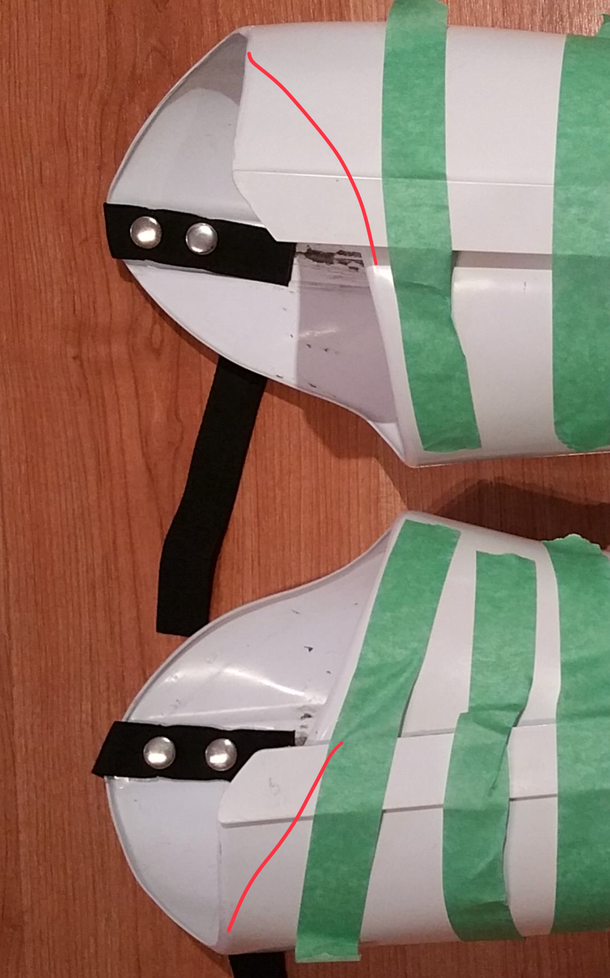
Additional Details Abdomen and Posterior Strapping Cut-Outs To better facilitate strapping later on and to prevent cutting pieces of the armour after painting as much as possible, I took a moment to make some cuts at the bottom of the abdomen plate and the top of the posterior plate. These cuts roughly replicate those that are included in the Anovos kits and will allow for easier access to snaps and strapping as well as increase mobility to a degree. 1) I made two notches beneath box #4 and the right edge of box #3, leaving the center of the abdomen in tact. Untitled by Taylor Goodson, on Flickr 2) I marked two cutouts on the posterior as well. I didn't cut down all the way to the top edge of the posterior plate (just like the Anovos version) as the belt sits across this ridge and it will look better if there isn't black from the strapping or undersuit showing beneath the belt here. Untitled by Taylor Goodson, on Flickr 3) I cut the marked cutouts and cut off the extra material on the sides as well, once again replicating the Anovos details. I also drilled the marked holes with a small drill bit just so I didn't lose their location during painting later on. These holes will be used to hold the snaps that will keep the posterior plate in place. Untitled by Taylor Goodson, on Flickr
-
Additional Details Greeblies - Clips The detail fun continues! Time to install the resin clip greeblies. 1) Prepare the resin pieces. The parts that came with my KB kit were pretty clean already, but gently sand away imperfections. Also, I reduced the bottom edge to around 1/4" - you can see the finished pair of piece on the left with the raw one on the right in the image below. Untitled by Taylor Goodson, on Flickr 2) Once the clips are prepared, it's time to glue them in place. But before we can glue them down, we need to shape them appropriately. The clips are perfectly flat, so in order to get them to sit nicely against the curved shapes of the armour, I used a heat gun to heat them slowly until they are pliable. Then, I held them against the pieces that there were to be glued against until they cooled into an appropriate bend. Untitled by Taylor Goodson, on Flickr 3) It doesn't take much of an angle - here's a side shot to show how they look once cooled. Untitled by Taylor Goodson, on Flickr 4) Now that they are shaped correctly, glue them against the armour. I opted for E6000 to better allow for the removal of these pieces later on if they chip or break. There are six small clips - 2 on each forearm and 1 on each bicep. Untitled by Taylor Goodson, on Flickr Untitled by Taylor Goodson, on Flickr 5) The large clips on the top of the thighs and shins are pretty much the same process. The only difference is that these clips sit across the overlap seam on these pieces. To help them sit more flat, I sanded down the region of the overlap across which the greeblie sits. It's hard to see in the first picture, but you can see it a little better in the second image. Untitled by Taylor Goodson, on Flickr Untitled by Taylor Goodson, on Flickr 6) Once those areas are sanded down a bit, the process is the same as the smaller clips - just E6000 and clamp the large greeblies against the leg pieces and let them fully dry. Untitled by Taylor Goodson, on Flickr 7) The last piece that needs the clip greeblies is the spats. Once again, shape them to the appropriate bend to mold to the shape of the piece. Untitled by Taylor Goodson, on Flickr 8) Then, glue the clip down to the outer tab of the spats. Note that we are only gluing the clasp part down to the outer tab of the spat - the inner part will be held down with velcro (or a snap - I haven't quite decided on technique just yet) at a later point in the build. Untitled by Taylor Goodson, on Flickr Greeblies - Forearm Rails In addition to the clips on the forearms, the detail rail needs to be glued into the groove at the center of the forearm's underside. Clean the resin just as before by sanding away any imperfections and getting the bottom flat and smooth. I opted for E6000 here again and clamped/magneted the piece down and set it aside to fully dry. Untitled by Taylor Goodson, on Flickr Greeblies - Chest Tabs Finally, there are two tab greeblies that go on the sides of the chest facing inward away from the depressed squares on each side of the chest plate. A dab of E6000 and some clamps (again) after sanding/preparing the resin bits is all you need! Untitled by Taylor Goodson, on Flickr
-
If you want to tighten the thighs at the rear, I’d recommend reshaping them by trimming that new edge into line with the rest of the thigh. The original photos you have (before adjustment) look quite nice, so I’d recommend reshaping them to replicate that.

-
Additional Details Abdomen/kidney magnetic closure Now it's time to start getting into the details of the ensemble (of which there are a lot!). First is the closure at the rear of the abdomen/kidney armour. After the test fit, I discovered where I needed to cut the back of the abdomen/kidney plate so they meet flush on the side in a form-fitting manner. I removed the extra plastic and rounded off the corners just to be safe from the armour snagging/tearing my undersuit. While I was initially researching the TFA TK build, I came across this thread here on the FISD about using magnets to close the abdomen/kidney plate. Big shout out to Josh ( @Jayben Kenobi) for an awesome idea. I'll briefly outline what I did below, but do refer to that thread for more information! 1) Create four 1" x 2" ABS plates. In the center of one half of the plates, drill out a circle wide enough to snuggly fit a large rare earth magnet. The x's are the positive polarities of the magnets - I always like making sure I know which side is positive/negative, especially when gluing is involved. Untitled by Taylor Goodson, on Flickr 2) On one side of the kidney armour, glue a strip of magnets against the inside of the armour. I used super glue around the edges of the magnets with a dab of E6000 in the center to just be extra safe as there is a lot of force working against the magnets. Untitled by Taylor Goodson, on Flickr 3) The plates will act as a socket to receive the magnets glued in step 2. I doubled each ABS plate with another piece of ABS to act as a barrier between the magnet in the socket and another magnet that is glued behind the socket to pull the magnet into the socket. (The magnets shown here are not functional for system - they are simply holding down the brackets for gluing) Untitled by Taylor Goodson, on Flickr I set the piece off to dry for a few days to ensure maximum glue adhesion - I didn't want to be toying with pulling against the magnets before the glue was completely set. Seam Filling The clean look of the new First Order TK's is enhanced by the lack of seams present in a few key areas - the forearms, biceps, yoke, thermal detonator, and abdomen sides. Typically, I would use Bondo for this part, but I made the switch to Epoxy Putty as I found it far more easier to manage in spots such as the thermal detonator. I found the putty to be easier to apply with fingers into very tight spaces, so I made the switch. I found that it took a little more effort to sand than Bondo, but I thought that was an acceptable trade for the convenience of manageability. I started with the biceps (also pictured is the tube of the specific product I used). First, I sanded the region to be filled to get rid of as many surface imperfections as possible as well as to enhance the adhesion of the filler. Then, I spread a healthy amount of putty into the gap between the two pieces and the surrounding area. Untitled by Taylor Goodson, on Flickr The thermal detonator proved to the be the most difficult to manage, but the malleable nature of the putty made getting into the grooves of the pieces that much easier. Lots of places to fill on the TD - end caps, bottom and side seams between the front and back tube pieces, and all the sides where the tube section connects to the back plate. Untitled by Taylor Goodson, on Flickr The side seams of the forearms need filling as well (much simpler than the TD thankfully!). Untitled by Taylor Goodson, on Flickr The back/yoke section. In this shot, you can see some of the sanding, too. Once the putty is dry, its a long process to get it nice and smooth and flush with the armour itself. I used 80 grit to get the putty down for the most part and then finished it off with passes of 220. It took a few hours per piece to get everything sanded down and flush, so patience is certainly key. Untitled by Taylor Goodson, on Flickr Before we can use filler on the sides, there is a section beneath the outermost abdomen boxes that needs to be closed off with extra plastic. I made a small 90-degree tab to fill in this area. It took a bit of trial and error to get the size of the piece right to fit against the open area beneath the box, but eventually it was closed off enough to allow for the putty to have something to adhere to. Glue/magnet the tab into place and let it dry before adding the putty (not pictured). by Taylor Goodson, on Flickr Untitled by Taylor Goodson, on Flickr Here is a final shot of all the filled pieces sanded and ready for further work. Untitled by Taylor Goodson, on Flickr
-
Preliminary Test Fit Completed Assembly So Far Here are just a few shots of all the pieces that are so far completed. I use the term 'completed' loosely as there is still quite a bit to do! Leg Components Untitled by Taylor Goodson, on Flickr Arm Components Untitled by Taylor Goodson, on Flickr Torso Components Untitled by Taylor Goodson, on Flickr Collected Components Untitled by Taylor Goodson, on Flickr First Test Fit Using a healthy amount of tape, I got everything in place just to see how things were coming along. The thighs have no suspension system yet, so I had to just hold them up. Also, the posterior plate wouldn't permit itself to be held on via tape simply due to the combating forces back there between the shifting plates and their temporary positions, so I had to forego that for the time being. Everything else seemed to work pretty nicely. Big shoutout to @Soulart for her fabulous (truly Phantastic!) gaskets - they are quite comfy and permit a surprising amount of movement! Untitled by Taylor Goodson, on Flickr Untitled by Taylor Goodson, on Flickr Untitled by Taylor Goodson, on Flickr
-
Assembly - Part V, Additional Details Left Shin Boxes The last chunk of this initial batch of assembly is the pair of boxes on the outside of the left shin. 1) The process here is nearly identical to the abdomen boxes. First, trim the boxes so that the edges match the surface of the shins. Untitled by Taylor Goodson, on Flickr 2) Cut a small length of ABS that nestles inside the shin boxes. Untitled by Taylor Goodson, on Flickr 3) Drill two holes into the ends of these strips and install a pair of chicago screws. Untitled by Taylor Goodson, on Flickr 4) Line the boxes up side-by-side on the surface of the shin. The bases of my boxes actually touch which easily lines them up as well as creates enough of a gap between them at the top. Untitled by Taylor Goodson, on Flickr 5) Drill holes into the shins for the four chicago screws. Then, install them very tightly to pull the boxes firmly against the surface of the armour. I like my shins to be form-fitting as I think tight shins improve the look of the leg armour (especially on the ANH TK's), so the relatively flat heads of the chicago screws won't dig into your undersuit or your legs which will be a blessing come trooping time! Untitled by Taylor Goodson, on Flickr
-
Assembly - Part V, Additional Details Thigh Holster (Note: originally, I had constructed my own holster out of ABS sheets as seen below, but I have since upgraded to the fantastic metal holsters provided by Dan! You can find his thread right over here.) 1) The thigh holster is a fun little piece. To start, you'll need to trim the base rail (the black ABS piece on the left of the image below) down to around 1/2" in thickness. Then, from left to right in the image, you will need a series of other pieces and designs that lay atop that. The first pieces next to the ABS base rail is are two strips of 1" x 8.5" ABS with angled and rounded corners. For the following three detailed pieces, I cut a strip of ABS 1.5" x 8.5". The extra .5" allowed for the additional .25" edges of the rectangular middle section that protrudes from the edges. To create this section, I measured 2.25" out from the very center of the strip to create a center box with a total length of 4.5". Then, I cut the top and bottom sections down to a total 1" thickness with the middle 4.5" remaining at the 1.5" thickness (.25" on each side). Then, I cut the corners of the central box as well as the corners of the full strip at a 45-degree angle and sanded them off. Finally, I cut the detail sections out with a very small Dremel sanding bit. I don't have specific measurements for these - I just followed images of the holster itself to get a rough estimate. Untitled by Taylor Goodson, on Flickr 2) After everything was cut, I glued all of the 5 ABS pieces together. I held them together with clamps as well as the holes that line up at the top and bottoms of the pieces - I installed a bolt and a wingnut to temporarily hold them together while the glue set. Untitled by Taylor Goodson, on Flickr 3) Next, drill holes that match between the ABS holster and the ABS base rail. Wignut and bolt are temporarily just for demonstration. Untitled by Taylor Goodson, on Flickr 4) For the left detail piece on the holster itself, I used a thick nylon washer and a rounded machine screw to hold it in. Untitled by Taylor Goodson, on Flickr Untitled by Taylor Goodson, on Flickr 5) Next is lining up where the holster will go on the right thigh. It should sit just in front of the overlapped edge (the back edge of the holster resting against the overlap edge). I drew where the greeblie will sit (2" from the top of the thigh, roughly) and put the holster 2" below the greeblie, making the greeblie centered between the top of the thigh and the top of the holster. Then, while holding the holster firmly in place, mark holes on the thigh itself that match the holes of the holster rail. Untitled by Taylor Goodson, on Flickr 6) Drill out the holes where marked and install the holster to the thigh. Untitled by Taylor Goodson, on Flickr 7) Finally, install two lock nuts on the backs of the holster bolts. You may need to cut the bolts down to get the ends of the bolts to terminate where the lock nuts are, otherwise you may tear your undersuit on protruding bolts. I cut a little extra from the ends of the bolts with a hacksaw until they no longer stuck out from the backs of the lock nuts. Untitled by Taylor Goodson, on Flickr
-
Assembly - Part V, Additional Details Detail Cut-outs There are small details to cut out on the chest, biceps, and shins - they will be backed with gaffer's tape after painting later on in the build. 1) First up is the pill holes on the chest. I started by using a small drill bit to get a majority of the plastic out from each of the 6 holes. Untitled by Taylor Goodson, on Flickr 2) I followed that up with a series of metal files to gently open the holes. I have a great small file set that has a few rounded files that were perfect for getting the correct shapes. Untitled by Taylor Goodson, on Flickr 3) Next, the central cavity of the chest should be opened up as well. You can also achieve the black effects here via decals, so opening this up is definitely optional, but I chose to go the gaffer's tape backing route here as well. I started by simply sanding down the back side of the detail area with a sanding drum on the Dremel until enough plastic was removed to open the section up. Untitled by Taylor Goodson, on Flickr 4) Then, once again, I switched to the metal files to get a nice, clean edge to the opening. I then went over the area with a bit of sandpaper (80 then 220) just to get the scratches and blemishes out for now. Untitled by Taylor Goodson, on Flickr 5) There are two details on the bottom of the shins that should be cut out as well. I did the same technique here of starting with the sanding drum on the backside before cleaning out with files and sandpaper. Untitled by Taylor Goodson, on Flickr 6) Finally, the holes on the outsides of the biceps. I did these the same way as the chest pill holes - start with a small drill bit and work your way up with a series of metal files. Untitled by Taylor Goodson, on Flickr
-
Thanks, @gmrhodes13! And congrats on the EIB FOTK's - certainly an inspiration! If you have anything to add, please don't hesitate - we can all benefit from your expertise, no doubt!
-
Assembly - Part IV, Thermal Detonator The thermal detonator proved to be a tricky thing to get correct, but with a bit of patience, a lot of glue, and quite a bit of trimming, it finally came together. It is assembled in 5 pieces - the 2 end caps, the front and back sides of the tube section, and the kidney seam cover plate. 1) Trim the front and back of the tube sections until they nestle together. I installed the outer facing tube over the inner facing one on both the top and bottom as I found that it fit better together that way. Untitled by Taylor Goodson, on Flickr 2) I started at the bottom seam as it was easier to get magnets in there first due to the shape. Lots of glue once again to get a good strong hold. Untitled by Taylor Goodson, on Flickr 3) Once the bottom was holding itself together, I moved to the top. Here, I used a bit of extra glue at the seams to fill it out as much as possible. We will be filling all the seams later in the build, but beefing this area up a bit with some extra glue makes that process a little easier down the road. Note: before gluing this section closed permanently, make sure there is enough space at the ends of the tube to permit the end caps to slip in. Untitled by Taylor Goodson, on Flickr 4) Once the front and back parts are held together strongly, remove the clamps and magnets. The complete tube sits on the bottom of the long kidney covering plate. I found the center of the tube and lined that up with the center raised stripe on the kidney plate and made a mark to help with lining the components up while gluing. Then, glue the tube to the plate at the bottom (there is a flat rectangle printed at the bottom of the long plate in the KB kit, so it's quite easy to line things up properly). Untitled by Taylor Goodson, on Flickr 5) Finally, install the pair of end caps into the thermal detonator. The right cap should sit flush with the end of the tube while the left cap sticks out about and inch or so. I used E6000 for this step as the slower curing time allows for more adjustment to get the caps to sit just right. Untitled by Taylor Goodson, on Flickr Untitled by Taylor Goodson, on Flickr
-
Assembly - Part III, Torso Components Abdomen (part 2) With the abdomen boxes ready to go, it's time to connect them using some internal ABS and chicago screws. 1) The first thing to do here was the create a series of pieces to fill the gap between the abdomen box top and the abdomen itself. I found that a stack of 5 ABS scraps was enough to fill that space. Then, between the second and first layers of scrap, I installed the backs of two chicago screws. I drilled a pair of holes into the topmost layer to fit the chicago screws into. Then, I cut a notch out of each of the sides of the 2nd layer of ABS scrap to allow the back of the chicago screw to nestle between the layers. Untitled by Taylor Goodson, on Flickr Here is a shot from the side to show how the notches permit the fitment of the chicago screws. Untitled by Taylor Goodson, on Flickr 2) Glue the ABS stacks into the abdomen boxes. (Note: for the larger box (#3), I created a larger size interior bracket - still 5 layers thick in total, but wide enough to accommodate a total of 4 chicago screws instead of just 2) Untitled by Taylor Goodson, on Flickr 3) Line up the boxes with the abdomen itself and drill holes that match up with the chicago screw posts. Untitled by Taylor Goodson, on Flickr 4) Finally, install the screws into the matching posts to pull the boxes tightly against the abdomen as flush as possible. Untitled by Taylor Goodson, on Flickr The view from the interior: Untitled by Taylor Goodson, on Flickr
-
Assembly - Part III, Torso Components Back and Yoke One of the more interesting parts of the TFA build is definitely the seamless back/shoulder piece. It seemed really daunting to me at first when I was building my TFA TIE, but once I understood what was going on, it wasn't nearly as bad as I thought. The section is in three pieces - the back plate, the yoke, and a bridge to link the two pieces. 1) Sand the faces of the components that will be glued - the inside top of the back plate, the outside surface of the connection piece, and the underside of the yoke. Untitled by Taylor Goodson, on Flickr 2) I attached the yoke to the connecting piece first. There are two notches that line up at the center of both pieces, so use that as a guide for fitment. I tested how these two pieces sat together many times before moving to the glue, removing plastic as I went that was keeping the pieces from sitting well against one another. Once everything sat the way I liked, I sanded down the edges, placed the glue, clamped/magneted, and let it dry. I used quite a bit of glue plus a lot of clamps/magnets in order to get the two pieces to sit tightly together as the glue dried. Untitled by Taylor Goodson, on Flickr 3) After the connector/yoke were permanently affixed, I moved to attaching the back plate to the connector. I did the same process with this - trimming edges that were getting in the way slowly but surely before joining them together with lots of glue, clamps, and magnets. Untitled by Taylor Goodson, on Flickr 4) As I've learned from my TFA TIE build, the yoke tends to take a lot of abuse and is quite prone to cracking. To help fight this tendency, cut a pair of spare ABS strips to fit into the tops of the yokes right along the shoulders. Untitled by Taylor Goodson, on Flickr 5) Using a pair of heat-resistant gloves, heat the cuts of plastic with a heat gun. Once they are soft enough, place them into the yoke to bend them into the correct shape. Once they are cool enough and have held their shape, glue them into place against the yoke. Untitled by Taylor Goodson, on Flickr
-
Thanks, Darren! A little preview of your fantastic belt - thank you again for sending it over so quickly!! Untitled by Taylor Goodson, on Flickr Absolutely - I can definitely confirm that this build is not for the faint of heart.
-
Assembly - Part III, Torso Components Abdomen and Kidney (part 1) The abdomen and kidney are another tricky component. There are seven boxes to attach to the abdomen plate while the kidney plate needs to be spliced in half and installed permanently at the sides of the ab. 1) Line up the seven boxes with the abdomen plate. On the insides of each box, I labeled them #1 - #7 (#3 and #6 are uniquely shaped - the rest are the same). I also marked the raised regions with the matching numbers just to be safe. Untitled by Taylor Goodson, on Flickr 2) Trim the flared lip off of the boxes to prep for install. Untitled by Taylor Goodson, on Flickr 3) Now comes the tricky part. Each box needs to sit flush with the armour which is curved, so the edges of the boxes need to be curved as well to permit that fitment. I use a large sanding drum bit on my Dremel to slowly remove the plastic until the desired shape/fit is achieved. Here are a few in-progress shots: Untitled by Taylor Goodson, on Flickr Untitled by Taylor Goodson, on Flickr Untitled by Taylor Goodson, on Flickr 4) Here are what the boxes looked like when I was finally finished shaping them. Untitled by Taylor Goodson, on Flickr 5) As I mentioned, the kidney plate needs to be split at the rear. There is a very clear indentation in the KB Props piece where the center of the back is, so simply bisect the piece at that mark. Untitled by Taylor Goodson, on Flickr 6) To ensure that I don't mix up the pieces, I mark where the back, sides, and top are on the inside of the cut pieces. Untitled by Taylor Goodson, on Flickr 7) Moving back to the kidney plate, install two large shims at the sides running from the top of the piece down to the top of the edge boxes. Untitled by Taylor Goodson, on Flickr 8) Glue and clamp as usual. Untitled by Taylor Goodson, on Flickr 9) Beneath the outer boxes, install a smaller shim to connect the bottom edge of the kidney plates. Untitled by Taylor Goodson, on Flickr 10) Once the shims are dry, install the kidney plates against the shims and flush against the abdomen plate. Glue/clamp/magnet/set aside. Untitled by Taylor Goodson, on Flickr 11) Remove clamps when dry and we now have a semi-complete abdomen/kidney region. Untitled by Taylor Goodson, on Flickr Untitled by Taylor Goodson, on Flickr 12) Quick test fit to see how the pieces roughly line up on the body. Untitled by Taylor Goodson, on Flickr Untitled by Taylor Goodson, on Flickr
-
Assembly - Part II, Leg Components Thighs and Shins The thighs and shins are relatively easy to assemble as they are just overlapped on both sides. 1) First, I test fit the pieces. The thighs were first. They are a bit low in this initial photo as there was a lot of extra plastic in the back preventing me from pulling them higher at this initial point (that's what I get for only being 5' 7" ). Untitled by Taylor Goodson, on Flickr 2) Once I got a little of that extraneous plastic out of the way, I taped up the thighs and shins to get a nicer fit. In this second picture, the parts were too close together at the knees, so more adjustment was needed to get things to sit right. It's an exercise in patience, really - trim little by little as it's always better to take less than to take too much, and use lots of painter's tape to hold things in place to let you feel and look at how things sit. Untitled by Taylor Goodson, on Flickr 3) Once you have the pieces measured to the appropriate size, the process is identical to the biceps. Unlike the OT TK's, the seams for the leg pieces are on the sides, not the front and back, so I overlapped the front piece over the back piece to get a cleaner look from the front. Just like the bicep, create a 'tab' with the underside piece and sand down the edge of the top piece for a clean look. Then, glue, clamp, magnet, and set aside to dry. The first were the shins - they are only closed on the outside, the inside remains open until much later in the build. Untitled by Taylor Goodson, on Flickr 4) Both shins assembled and drying: Untitled by Taylor Goodson, on Flickr 5) The thighs, however, are sealed on both sides. I glued one side at a time as I find it's easier to manage - gluing both sides shut simultaneously has a little more room for error. Untitled by Taylor Goodson, on Flickr 6) After the first side is solid, seal them closed and set them aside to dry. Untitled by Taylor Goodson, on Flickr
-
Assembly - Part II, Leg Components Spats Now it's time to turn the attention to the lower appendages. 1) I started at the bottom with the spats as I was the most curious about these. The first thing to do was to glue on the rear extension piece. I used a similar method here as I did with the bicep overlap - shape the underside piece of the overlap into a tab shape (cutting off a little of the edge and rounding corners) to allow the fit to be more comfortable. Untitled by Taylor Goodson, on Flickr 2) Then glue the extension piece onto the tab. Clamp and set aside to dry. Untitled by Taylor Goodson, on Flickr 3) Do the same for the opposite spat. That's all for now - this first round of assembly is all just rough, general stuff. Untitled by Taylor Goodson, on Flickr
-
Assembly - Part I, Arm Components Test Fit Now that the forearms and biceps are assembled (well, half-assembled for the biceps), it's time to test fit them with the gaskets. The overlap for the bicep closure is the most important measurement in this process as that will allow us to seal off the biceps. 1) Use a large strip of painter's tape to hold the biceps together at the overlap. This will allow you to adjust them as necessary while you are testing the fit. Be sure to allow to leave enough room for the gaskets - something a little different than our standard OT TK builds. I definitely recommend testing fitment of components with your undersuit and gaskets as much as possible to get the proper fit. Untitled by Taylor Goodson, on Flickr Biceps (part 2) 1) Now that the test fit is done, we can close up the biceps. Mark a line where the two pieces overlapped when they were still held together with painter's tape. I cut the under piece of the overlap into a tab shape by cutting off a little bit of the top and bottom and rounding off the edges. This helped the pieces nestle together better as the KB molds don't have any built-in overlap demarcations. Untitled by Taylor Goodson, on Flickr 2) Before gluing, I sanded down the top edge of the overlapped piece to get a slightly tapered edge just to give the seal a little more of a finished look. Untitled by Taylor Goodson, on Flickr 3) Finally, glue, clamp, magnet, and set aside to dry. Repeat the same steps for the opposite bicep, too. Untitled by Taylor Goodson, on Flickr
-
Assembly - Part I, Arm Components Forearms Now comes the first tricky part of the build - the forearms. They are constructed of 4 separate pieces in the KB kit which is luckily fewer than the Anovos kits thanks to box that is included in the mold instead of a separate piece. 1) First, roughly assemble the forearm to test fit it around your body. I use a good deal of painter's tape to hold everything together while I try to slip it around me to make sure I don't cut too much plastic away. Untitled by Taylor Goodson, on Flickr 2) In the image above, you can see that I marked where to trim the excess plastic with the gold marker line. The size of your forearms will vary based on your body, so be sure to test fit a couple times before trimming anything away! 3) Once the fit is tested and the cuts are made, it's time to install another set of inner shims. These will connect the two side pieces to the main forearm body. You can install both shims to the main body of the forearm - I installed mine separately (one on the main forearm body and another on one side piece) just to allow more room for clamping. Untitled by Taylor Goodson, on Flickr 4) Once the shims are dry and in place, glue the components together. Magnet, clamp, and set aside to dry. Untitled by Taylor Goodson, on Flickr Untitled by Taylor Goodson, on Flickr 5) Duplicate for the other forearm, clamp, magnet, and set aside to dry once again. Untitled by Taylor Goodson, on Flickr 6) Once the side pieces are dry and assembled, glue in one side of the detail plate. I held it in place with some clamps. You'll notice that I only glued the rear portion of this piece - that is to allow the front of the forearm opening to flex around the wrist more easily. Untitled by Taylor Goodson, on Flickr 7) After the first side of the detail plate is glued in, glue the second one in the same way. After both sides are dry, you should have one solid forearm piece. Untitled by Taylor Goodson, on Flickr 8) Slip it on to ensure the proper fitment. Untitled by Taylor Goodson, on Flickr
-
Assembly - Part I, Arm Components Biceps (part 1) The first armour piece I assembled was the biceps. For some reason, I always start with the arms with my armour builds - I find it's a relatively easy part to help get acclimated to the maker's plastic and pieces. 1) The biceps are constructed with an inner shim along the longer (outisde) edge and an overlap at the shorter (inside) edge. Using some scrap ABS from an older build, I installed the inner shims against the insides of the longer edges of the biceps. For adhesive, I use ABS cement to bond the plastic components together, but only when I'm sure of the fitment. The ABS cement is very difficult to pry apart, so for anything I'm not absolutely certain of, I use the trusted E6000. However, I like to use the cement when I'm confident as it prevents me from being stalled to wait for the long cure time of the E6000. Untitled by Taylor Goodson, on Flickr 2) Once the adhesive is dry, match up the matching long bicep edges to the inner shim. Glue them together, clamp/magnet them, and set them aside to dry. Untitled by Taylor Goodson, on Flickr Shoulder Bells While the biceps are drying, I moved to the shoulder bells. The only thing that needs to be assembled is the inner tab that creates the extra edge at the top of the bells. 1) Using a pair of large clamps, line up the inner tabs so that they extend from the top edge roughly 1/2" or so. Untitled by Taylor Goodson, on Flickr 2) With the inner tabs firmly held in place with the clamps, I used a silver sharpie to outline where the tabs sat on the interior of the bell. This will give me a marking to line up the pieces when we move to gluing. Untitled by Taylor Goodson, on Flickr 3) Roughly sand the interior of the bell and the outside face of the tab to enable a strong bond (I do this for all glue joins when possible), then apply glue, line up the tab with the marker lines, clamp, and set aside to dry. Untitled by Taylor Goodson, on Flickr 4) Duplicate the process for the other shoulder bell as well, then set them aside to dry. Untitled by Taylor Goodson, on Flickr
-
Wow, thank you! I'll do my best to keep everything documented in that case. I certainly will, thank you! Your belt is fantastic - I'll be diving into that this evening. It is definitely an exercise in patience! I would definitely not suggest the FOTK armour as a first build for anyone - I've had to pull from a whole pile of building techniques I've amassed with all the other costumes I've completed to date. I enjoy a challenging build, though, so my experience has been great. The guys at KB Props have been a pleasure to deal with, too, so I would absolutely recommend them for armour - just be patient as with any other builder as good things take time. I would probably do it again, yes, but I'm not at the finish line just yet! haha
-
Fantastic, thank you for sharing!