usajdm
-
Posts
26 -
Joined
-
Last visited
About usajdm

Recent Profile Visitors
1,044 profile views


-
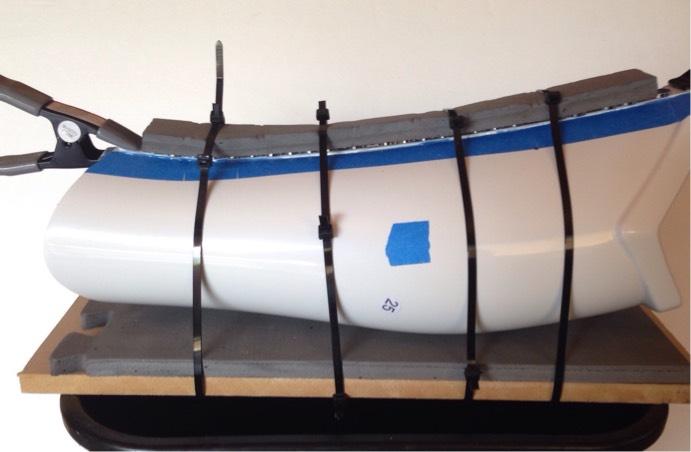
Here's an example of what I was trying to explain in my post above.<br>
-
Just to share a method I used.<br> I cut 1" strips of Eva foam mat the length of the cover strip.<br> Clamped, magnets, then laid the foam over the strip and used wire ties(zip ties) to apply added pressure on the piece.<br> Worked really good.<br> Don't over tighten the ties or it'll concave the butt ends.<br> Look inside the piece while you tighten to be sure the joint has stayed flat.<br> Place all the ties on the piece, then start from one end tightening them.<br> Sorry I didn't take any photos of it.<br> A tip, use a strip of foam on the opposite side to keep the wire ties from shifting.<br> It gives them something to bite into instead of the slick surface of the armor.<br> Robert
-
You guys are Awsome!<br> Thanks.<br><br> But be ready.<br> I'm at that point where all the questions are comin.
-
Another quik question...<br> The backs of the shins.<br> Is the cover strip side supposed to overlap the other side, or should the two sides butt up against each other?<br> And I don't mean just the cover strip.<br> I know that overlaps to cover the seam.<br> I mean the whole thing overlapping to create a tight fit.<br> Robert
-
Gotcha
-
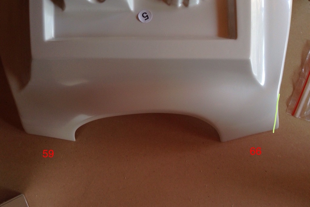
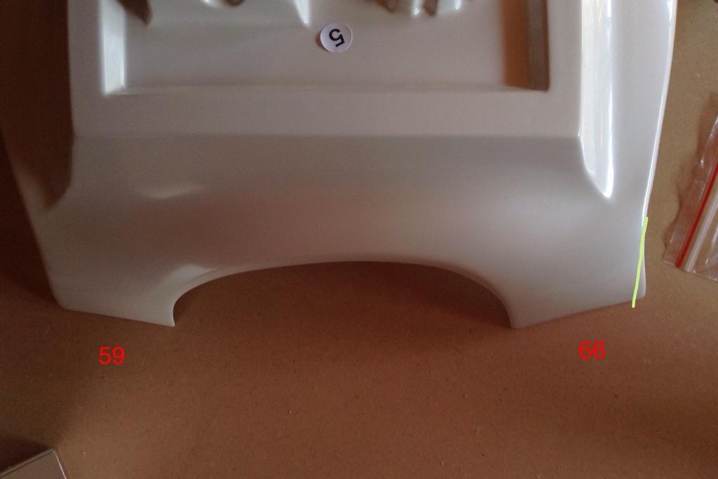
This is what I was talking about.<br> I can trim on the green line to even them out.<br> What do you think?
-
Is it recommended to trim the back shoulder extensions to match?<br> I've got 59mm on one side and 66mm on the other.
-
Ha Ha!You funny guy. I knew I was askin for it, but I had to be sure. Measure twice, cut once. Thank you, Robert
-
I'm sorry everyone.<br> I know this is a silly post, seeing how it's all been covered.<br> I'm hoping someone could list out for me all the return edges that are supposed to be removed.<br> Starting on my strapping and such real soon, but wanna make sure I haven't missed anything.<br> Easy to have left something out, seeing how many pages this has stretched over.<br> Thanks everyone and a big thanks to you Tony.<br> Robert
-
Hi Andy, Finishing up my E11 soon and would like to give a go at making my own power cylinders. Please don't be offended, I'd love to own a set of yours. Just not in the budget right now. I've read page after page of your threads and PDFs and I think I've got a pretty good direction to go in. What I was hoping was that you'd be willing share some demensions with me. All I've got are the diameters of the cylinders and the metal mites. I'm stuck on their lengths and...
-
 Who do I report a recast of MY work too?
 -
First off, hello.<br> Now, your common AA puts out I believe approximately 1.2-1.5v at 4mah.<br> So even in series your short on amps.<br> Put that together with less volts then recommended, and the fact that the motor is seeing a "load", your just not giving it enough juice.<br> You could always wire in 2 more AAs in series to increase amps, but your still short.<br> With proper amperage it "should" turn the motor even at 2volts, but will be considerably weak.<br><br> Now the bad news....<br> With proper volts and amps I highly doubt you'll get the water output needed or desired.<br> Even with a pressure producing nozzle, I just can't see it working.<br> If you really want to push on with the project, you might want to look for a "high flow" pump.<br><br> Do try hooking up 2 more AA in series and see what kind of an output you can get.<br> Also you can try a single 18650 battery.<br> They put out 3.7v and come in a variety of amp ratings.<br> Keep in mind, 1000ma=1a.<br> Good luck,<br> Robert
-
Disney's stormtrooper voice changing mask
usajdm replied to ikartev's topic in Build Threads Requireing Maintenance
Glad this is working out. It was pretty clear it was crossed wires. Let me add alittle more if you don't mind. Be very careful if you decide to drill into the pcb. It's very easy to damage the traces. Also, some pcb's have internal traces that can also be damaged. A properly soldered joint should not need to go through the pcb. Also, it may just be the picture, but be sure the exposed copper of your +'s and - wire are not touching. Heat shrink tubing should be covering those exposed wires. Remember, you only need alittle wire exposed to get a good joint. Cover the rest. Again, that might just be how it looks in the picture. As far as "sealing" the board, may I recommend silicone. The stuff you buy by the tube at home depot is fine. Be sure it says 100% silicone. Great seal and if you ever need to remove it for pcb work, it'll peel right off. Please keep us informed on your progress. -
Disney's stormtrooper voice changing mask
usajdm replied to ikartev's topic in Build Threads Requireing Maintenance
Do keep in mind that standard solder won't stick to aluminum, stainless steel or bronze wire/pads. Your wires do look to be primarily cooper. That soldering station looks like it should do it. Alittle bit of flux and I'm sure it's gonna work out for you.