
kev011
-
Posts
51 -
Joined
-
Last visited
-
Days Won
2
Content Type
Profiles
Forums
Gallery
Articles
Everything posted by kev011
-
Happy Holidays all! In some quiet hours I've found a few minutes here and there to head out to Santa's workshop to clean up the blaster. When I got the fresh soldered parts back I found that all the work I'd put into making the new receiver cap flange now didn't fit. The magazine also didn't want to go in, but after a lot of filing and careful prep, both fit on very nicely now! The stock folds out and latches nicely too. I was a little worried about this part. I put it all back together with the Sterling parts first to make sure it all fit. I'm still debating on my aluminum bolt and what I want to do with that. It will certainly make it lighter! I'm also looking into some easier paint options. I'm leaning towards the two part rattle can (in a can) tech of Duracoat. It's already designed for firearms and apparently holds up well. In the meanwhile I'm waiting on my t-strips and probably start looking at some reference for the scope rail. It's getting exciting now!
-
I got my pieces all back together with a big thanks to my buddy. There's going to be a lot of touch up areas I can already tell, but it is what it is. Biggest ordeal will be smoothing back down the receiver butt cap sleeve as it "expanded" some from the heat and the silver solder. it also has some solder in the threads of those hook shapes that is going to take a lot of time and effort to remove. I can't really complain as I pulled in a favor for this so the price was right and honestly my best effort may not have even come close to this, but I'd hoped for less work than what I'm in for. Thanks again, Aaron on all the tips on this! I'll see how kind Santa will be to me this year and try and trade my coal lumps for power cylinders!
-
Wow! The detail is making my head hurt! You'd mentioned that the auto parts store had the right stuff, but I didn't see what it was? Maybe I missed that in the thread. Was it brake line or something? Small pieces are always the hardest. Andy's price tag isn't looking nearly as bad. Yours is spot on and beautiful too!
-
I want to send you my finished metal for that paint job you did! I keep looking back at your thread. I also need to start finding parts for the power cylinders. Anyone got a good builder thread on that one? I've seen the super nice ones for sale but I think I'd rather keep this project as 'home grown' as I can
-
One thing you could do is completely drill through the firing pin area, like a 3/8" hole. I guess that's the same as you're saying too. That wouldn't effect the look but would certainly stop you from ever firing again. That would be a lot of work though… A plug in the barrel would be another option but then you loose the option to put a light down the barrel. Just had another thought: You could not cut out the mag well. This would keep anything from entering the chamber. The magazine would need to be moded as well so it still stops and stays in place. That would be good in conjunction with milling out the bolt. I'll keep thinking about it.
-
Finally everything is going together. I brought my bucket of parts over to my buddy's welding shop to start reattaching all the bits and bobs that we'd torched off a week ago. I'm a bit nervous to turn over all this hard work to this point but it's gotta happen. All the parts were tacked on with a TIG to make sure everything is where it's supposed to be. Hopefully in a couple of days I'll get a call. Hopefully before Xmas if I'm lucky!
-
Yes, one of them was buried under paint and didn't have much of a slot left on it to turn. It was the headache in the end.
-
I played with the scope some today. When I say "play" it was mostly a lot of anger and curse words... So I have two scopes: 1) M77C and 2) M38. The M38 being the correct shape of the scopes used in ANH. The M77C had great optics and the M38 had fudged up excuses for optics. So my plan was to transplant the good stuff into the right stuff. What I discovered was this wasn't as easy as I thought and removing the rear lens from the M77C (for whatever reason) was a real pain that took hours and a lot of hand gouging. It didn't want to come out, but I'm persuasive. I don't have an pictures of working on it because it was a lot of just me angry. But when I put the M38 back together, I did cut out a piece of 1/8" Red plexiglass and sealed it in behind the outer trim ring. I took this at exactly the right angle but the scope needs to be adjusted. I wish I knew more about how to adjust it! (My hands are really beat up right now from working in the cold and metal that needs to get scrubbed out. Sorry) Yes, it was a Bapty. This is just a typical, non-firing version. Basically the only ones that have the clearing strips and the spring will be live fire versions on screen. If the particular shot doesn't call for a blaster fight, they won't be using "sterling" (live fire) versions on screen. The one in the ebay listing (which ended at over $30K and didn't meet reserve!) was identified as an onscreen one used in the scene where the StormTroopers bust in (and one bumps his head on the door) and find C3PO and R2D2 hiding in the closet. They had the screen shots to identify it. That was filmed in London. So I think there can be a little confusion on what was used where. Basically it breaks down to firing and non firing. Firing ones aren't typically used in scenes where there isn't a call for gun fire, just dummy versions, like in the ebay listing. It's a safety issue and there needs to be an on site armorer who's there when any live fire versions are out. Update to this point: I'm a big fan of the Tested webisode series. The guys from Mythbusters do some shop talk about props and even builds. I think most folks here would enjoy watching any of the builds. This clip is about props from Tarantino films but they talk specifically about what I was trying to address above. https://www.youtube.com/watch?v=JUxrCFxavO8 At 7 minutes and 17 seconds in, listen to the story of real vs resin guns. I've worked on a few independent films and even though they are low budget, they still follow the guidelines of only using firing props for the specific shots where the gun actually shoots a blank and immediately switch to the fake/prop/resin ones after they hear "CUT". That's what makes this hard as you see so much variance in who's holding what gun and how they seem to switch. There is also an interesting documentary on the whole Star Wars saga where Lucas talks about how all the scenes on the Death Star were sped along in ANH because the studio wanted them done weeks prior and over budget. The crew was split into shifts to accommodate the shooting schedule and still get the shots done in time. This would probably be a reason why the props were falling apart as there wasn't time for them to get fixed while shooting nearly around the clock. Lot's of interesting facts about Star Wars!
-
I hear you guys. I think there is a fine line between what is and E-11 and what is a Sterling. We start to get into esoteric grounds that I'm unclear on which way is considered right and which way is wrong. In the end, it's my build and I'll do as I see fit and it will be very nice no matter if people think it's wrong or right. If you look at that ebay link I put up, you see a blaster that was used, up close on screen. Yes, it's a non firing version, but so will be this Blaster too. Here's those pictures from the eBay listing: It's clearly one part Sterling and the other parts are cast. The receiver was cut and a cast rear end was graph on it. In fact in the listing the bolt was painted black on the screen shot. But, no spring, no clearing strips.
-
A little update on some quick parts. First up was shortening the clip (magazine). I basically took off 1/2 - 2/3's of the total length. I'd been studying the actual prop on ebay (right now) that I listed in the very first post. It has many nice detail shots of a screen used E-11. http://www.ebay.com/itm/Screen-Used-Star-WarsThe-Empire-Strikes-Back-Stormtrooper-E11-Blaster-Original-/331412168597 With the clip in, it makes a nice little bud hanging out. These clips seem to vary in length all the ones I'd seen around the net, so using the ebay one as a good reference, I'm pretty happy. There's not much to cutting it off other then getting the cut straight. After that, a little filing down of the short ends and bending the long sides out and fitting the butt cap on the magazine. I cut down the spring and kept all the internals to it. The rollers are still in the clip with the spring. It could still hold a few rounds I suppose. One thing I've been thinking about to eliminate getting in hot water as to make a new bolt. Looking again that prop, it appears to have a solid core where the spring action would be. I decided to make up a solid bolt. I used an aluminum tube and a solid rod of the same as a plug in the middle. If I recall, it's a 3/8" bore all the way through and then counter sunk just a tad so the lever sits just below and will slide in. You need to have a chunk cut out to allow for the magazine to fit and lock in. So, you drop in the pin when you line up with the receiver tube, then slide it back Here it is closed. . Looks like the ID of the aluminum tube is 1.125". I still can use some of the spring to keep tension on the receiver cap or possibly have some room for electronics stuff. I don't know much about the fancy sound cards and control boards, but it might be fun to do something with that as well. Still needs some more polishing, That's it for now.
-
Awesome. I'll keep my eyes peeled. For photos, I started a thread here: http://www.whitearmor.net/forum/index.php?/topic/29486-Chopped-up-Sterling-project-%3D-E-11-Blaster
-
Thanks for the link. Now I wish I didn't read past page one of that thread. Way more drama then I could have imagined! Ugh!
-
Thanks everybody! I'm pretty happy with the results. I just wish it was going a little faster! I gingerly cut off the sleeve from the longer tube: Slides right on the receiving tube: And the cap fits nice. I think I'm just about ready to reattach the bits now. I have to align my schedule with my buddy who helped me burn the pieces off to reattach them. In the meanwhile, I may mess around with the scope: Also, looking for advisement on the t-track. who's got the good stuff for blasters?
-
I still can't believe you were able to graph your two ends to your tube! That seemed like the hard way to me, but maybe that was easier in the end. I need to re reference your soldering tips again as I'm getting close to that. Do you recall having to groups the parts and solder them at the same time so they'd go together?
-
So I'd mentioned that the butt cap sleeve was mangled in the heating and beating process. Above is that horror story. Now for the task of recreating that piece to put it back together again. This is one of those times I wish I had done all the measuring before breaking it. I did my best job to make estimations on that sleeve and made my own template above. This tube is the same Chrome Moly 4130 Alloy Steel but is 1.625" x 0.065". The ID of this tube is close, really close, but some sanding on both the receiver tube and the sleeve will need to happen to make it slide over as there's about 1/100th of an inch that needs to come off to get them to mate. So, first things first, made the sleeve fit. After sanding both pieces, time to clean the sleeve tube again with alcohol and paste on the template on, just as before. I primarily used a demel tool on this with my smallest diameter cutting wheel. I just tried to get it close and then file away. This was another pain in the butt for filing. Probably about 2 hours in all to make the initial cuts and another 2 hours of careful filing to get the cap to get on and turn into place. Here's the old and the new. Hard to believe that I was able to get this to work, but it does. I just need to cut off the sleeve tube and it will be ready to go on. Here's some details without the template on. Above I tried to make some steel T-track. that's not going to work after an attempt. Too much work and far too heavy in the end. Here's that dovetail cut. holes and yeah, that's about it for now. hope you enjoy
-
I left off on the gun site. This seemed to take me a long time to carefully file in the dovetail shape to fit the site. If you aren't concerned about getting it right, I don't bother! It's pretty time consuming and you'll need a few different shaped files to do it. Now the only hole left to take care of is for the bolt pin. I drilled out the larger hole at the end and two guiding holes on either side of the 6" space. I debated on how I was going to cut it and keep it straight. In the end I called another friend of mine and asked if I could use his Mill. Again here I don't have any pictures of the piece being milled as I was working the machine and trying to keep track of the numbers. It's like working an etch-a-sketch so if you turn the knob the wrong way, you end up messing up a few days worth of work. So sorry, no photos of that. I will say you need to be very careful when clamping it down in the mill table vice because it can easily distort the shape of the tube itself with too much pressure. I recommend buying a chunk of doll rod that is as tight as you can get it to fit inside the tube so you don't have a distorted cutline. While over there I also wanted to shave my end of my tube which I'd previously left a little long on purpose because I wasn't clear when I cut it with the saws-all if I had the measurements 100%. We took 1/8" off the end which should be perfect (fingers X'ed) Now for some quick mock-ups to see where I'm at. Next up (still working on this part) the receiver sleeve for the butt cap.
-
After getting the majority of holes to shape and taking a lot of measurements off the original parts, I contacted a friend of mine who's family runs a welding shop about silver brazing/soldering. He told me about the process of how these bits are attached and also informed me that my Mapp Gas and propane torch wouldn't get the parts hot enough to take them off. Thankfully he offered up his oxy acetylene torch to help me out! I wish I had more pics, but I don't. This was a two man operation which I was on stand by to grab the pieces off with tongs. Most bits came out fairly easy…. but then I learned some lessons that I should share: The barrel tip is silver soldered on, but I didn't know about the registration pins in the tube that held it in place. I also didn't know that the end of that tube is curled over to shape it to the barrel. Knowing now, I would have cut that tube close to the end of the barrel and tried to weld it in place rather than bash things up trying to get them out. The other part is on the opposite end. The butt cap which has a sleeved piece with the grooves in it to hold the cap on didn't want to move. So when we got a little more aggressive with it, that sleeve was destroyed. Again, I wish I would have cut it off and just welded it to the end of my tube. Live and learn. All the pieces that came off still had some silver solder on them which needs to be removed for the best reapplication. In this photo you can see this brassy like color on the edges, that's what needs to be removed. I tried sandblasting it off and it really didn't do much other than help me see where it still was vs the base metal. In the end about a day was spent carefully trying to file away all the resident solder. What I also learned is many of these bits have registration pins on them which need to be drilled in the tube as well. So I headed back and forth between my work area and my computer to update the template as I went along. I recommend cutting and filing modestly at first, leaving fat edges. This piece that takes the mag receiver to the tube will have a very low clearance between the two pieces and the fit is pretty darn tight. I've seen a few variations to the bayonet plug. Some builds seem to have a square hole in their tube while others are rounded. Mine was an oval which I had to carefully grind into shape. At this point you're probably wondering why I haven't drilled out all the venting holes in the tube. Well, I don't see a point in drilling out holes that you just end up covering up in the end, but that's me. I'd also like to save myself the time and lastly have as much surface area to glue or attach the T-track to the receiver. Make sense? Now, onto the harder holes to cut.
-
I found on another website for people rebuilding sterlings the specs on the actual receiver tube. 1.5" x 0.058" X 1.384" Alloy Steel tube. (4130, Chrome Moly to be specific) This is the proper fit for both the OD and ID so all the bits fit. I ordered a 3' piece as I knew this would only be 18" in length, I would have a spare if I messed up. The reason why you want to use this particular tubing is it's drawn, which means it doesn't have a bead weld on either side of the tube and it's also exact dimensions. If you look online you can find suppliers pretty easy. After I got the tube and cleaned it with rubbing alcohol, I printed out my own concoction of holes to drill and glued it to the tube. I'll post my layout later as I'm still tweaking it and don't want to put up misguided directions that someone will follow. Next up was how to drill top dead center on my little drill press. There are tools out there that you can purchase that have a 90º angle to them to let a cylinder shape next nicely on the work surface. I elected to just make my own out of scrap steel I have sitting around. I took two pieces of angle and tacked them to a steel base plate and drilled holes for bolts to mount them to the table. This worked great! Because some of the holes are out towards the end of the tube I needed something to help stabilize the end of the tube. I had a hole cutter that was slightly larger than the 1.5" OD of my tube and used a scrap piece of wood I mounted to my table to help guide me. Because of the nature of the way the 90º holds the tube, as long as your bit is centered on the bottom of the V, it's going to drill top dead center. Although I used a center punch on many of the holes, I actually found it easier to drill if I didn't premark the holes like that, for the most part. I started with a bunch of 3/32" pilot holes across the board and then stepped them up to the sizes I needed, slowly. For the larger areas I used a dremel tool with a cut off wheel to get the generic shape and then I spent forever filing to final sizes. Next up: torching.
-
Because I could never afford this, I'm making my own After I signed on and posted up that I've been planning and plotting to change up a heap of metal bits to be a blaster, I was asked for a few pics, so I thought I'd start a tread. Hopefully this is helpful to folks hoping to do the same as many of the threads were for me. Everyone has their own set of skills, abilities and tools to make a build happen. I have a pretty modest set of all of the above mentioned. So working with what I have and calling in a few favors from friends with better set-ups than myself, I set off with the goal for a fairly generic build. I see a lot of folks getting very specific in their builds even mimicking specific troopers/heros weapons. Mine will not be that "intense". Starting with all the cut up bits, I placed them together out of the box to get a sense of how big this thing is. First impression is that it was much smaller than I thought it would be. Funny how the big screen plays tricks on us. Basically I had everything minus the receiver tube that I would need. Thankfully there seems to be a lot of templates out there. What I realized after studying many of these templates is that they were really designed to be used on PVC pipe and only mimic the general approximation of hole locations and such and didn't completely work for me, but it was a great start all the same. Between the one set of prints for an E-11 blaster and another set from an airsoft Sterling mod and my own careful measuring, I put together my own set of templates to work from, and to date, it seems pretty good. First up, I needed to clean up all the bits. There was a heavy coat of oil on all the metal parts and old paint as well which needed to go. I took these parts and left them overnight in a 1 gallon bucket of carb cleaner. After soaking and wiping down with a paper towel, resting on some cardboard, I had relatively "clean" parts to look at and handle. For the larger parts that wouldn't fit in the bucket, I used some airplane stripper and finished with a wire wheel on my 4.5" grinder. on to the next part of setting up
-
Tell me more! I'd be interested in the proper eagle logo.
-
That was the ticket. Two small tabs on either of the short sides popped it off. Thanks a bunch! I'll be assembling my E11 building thread here soon. I still want to get a smig further along and I'll post up where I'm at.
-
Yes, mine is a big H logo version. I was looking at this tread this morning. Mine has no screws on the outside of the counter area, so there must be a squeeze technique I haven't discovered. Thanks all the same. Anyone else?
-
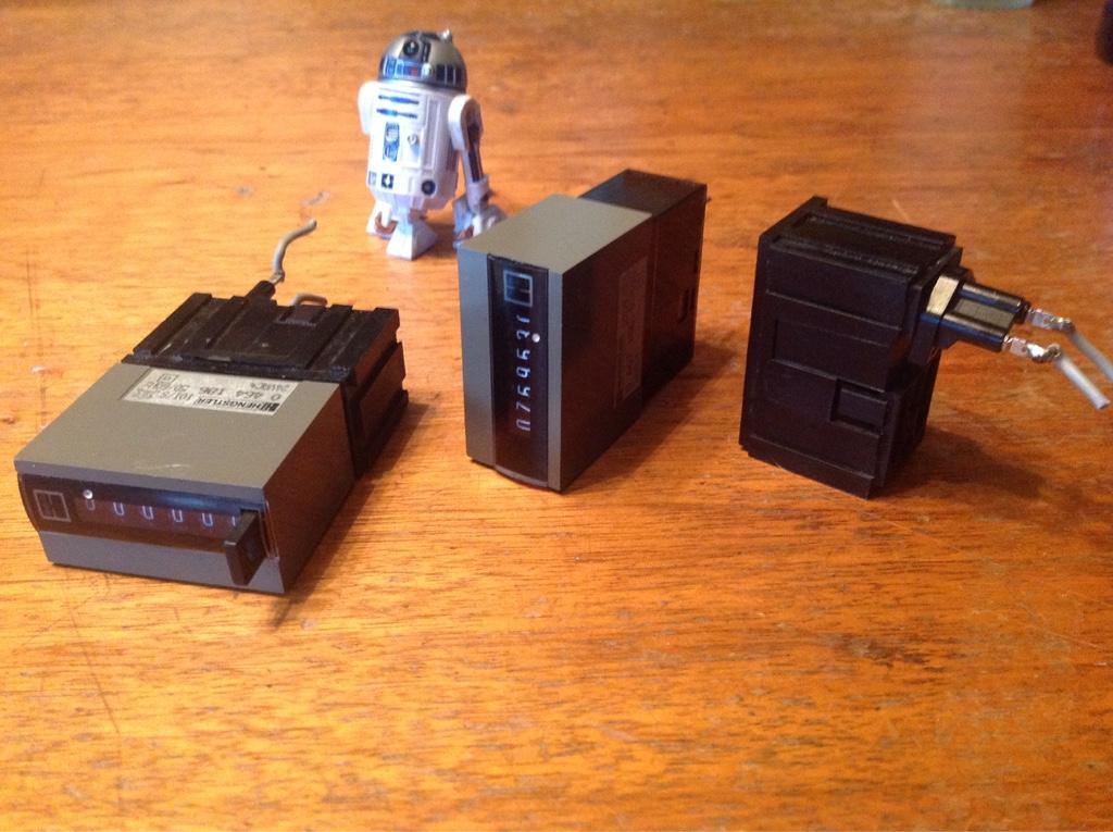
I have these more modern 400 series Hengstler counters and I was planning to modify the one with the reset button / 6 digit for my blaster project. I can easily remove the black shroud that has the pins sticking out but I can't seem to find a way to remove the greenish color cover from the front, nor slide the lens out. Before getting all strong arm on this I figured I'd write the experts here on some advice. Anyone else have one of these that they opened up without shattering? (Note: I realize this is not the famed Eagle logo version but it's still better than a hunk of resin in my opinion. I may purchase a resin version just to graph that logo to the shroud down the road if I'm feeling disgustingly accurate)
-
What a spectacular thread with so many details I was searching for! Thank you for taking the time to detail your whole process. I am in the beginning process of reconstructing a cut up sterling to e11 of my own so I appreciate the insight.