


Khazid
-
Posts
370 -
Joined
-
Last visited
-
Days Won
1
Content Type
Profiles
Forums
Gallery
Articles
Media Demo
Posts posted by Khazid
-
-
Start with a little return edge on every piece, then remove to match the CRL's (i.e. no return edge on forearms at the wrist). When doing your final fitting, you'll find return edges in some places (i.e. butt plate) give one heck of an armor bite, so you'll start trimming back in those places as well.
It is much easier to remove the plastic in little bits than it is to try and fix a mistake by adding it back.
-
 1
1
-
-
EVERYONE that has posted deserves a beer, I really appreciate both of you takin' a look.
 Brandon my man, you're from Simi?! I grew up next to Moorpark High, went there for 2 years and then moved up here... I miss SoCal so much. You guys have sales tax though
First motto I learned here: "Troopers helping Troopers!", so no thanks needed.
Yes, my family and I currently reside in Simi, it's our second time in the city and I believe we will be here for quite some time.
Sales tax, property tax, gas tax...bleh too many taxes in California if you ask me, but the wife likes it here. Happy wife, happy life...
-
2
-
-
You can get lens strips from trooperbay. Any dark green welding mask replacement face plate will work as well (harbor freight).
-
Parts 2 and 3 appear to be your right. 1 and 4 look to be the left. I bekueve there is a tutorial arelound here somewhere on how to identify them, but the link escapes me.
Maybe Tony or Mathias have it handy...or any other grizzled vet.
-
Not a bad idea Brandon, never thought of that. I wonder what the cost difference is between there and let's say ATA. Tarrell sells two sheets (approx 14" x 24") for $25 with shipping.
Good info here.
3 sheets of 1mm styrene that are 16"x24" sell for 14.99+tax at my local hobby store.
-
This is a great build thread as someone who is also working on one thank you! Please keep up all the great posts and detailed pics.
No problem, I will keep the pics coming that is a promise. I appreciate the kind words.
Too many "K" builds going on at once. (:
Power to the Krazy K's!!
Still old enough to be my dad! You two enjoy! Brandon, you'll probably beat me but we need to get our MTKs completed! There's not enough of us
Jeez, with me at nearly 43, I guess that makes Tony my older brother. There's some love for ya my new friend.
Disneyland was great, had too much fun with the kids. Not sure about beating you on the build. I have lots of plans for the bucket that will be revealed soon. Going to need to take my time to ensure from the outside it will look like a traditional TK. Of course, that means breaking out the soldering iron again...electronics here we come!
I hope some day MTK makes the vetted armor makers list. Every post someone puts up asking about makers I try and throw Mike a bone by mentioning the kit. If all us MTK owners did the same, maybe TPTB (The Powers That Be) would get him added in.
-
Build Log – 7/2-7/12 – Legs and Bucket
Like I mentioned in my last post, I have a small update to provide. All the following was work actually done on 7/2-7/4. I haven’t worked on the build since that point. Work and life commitments have been too hectic.
First up was the gluing of the last interior strips for the thighs.
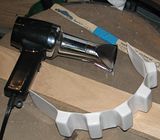
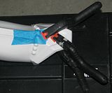
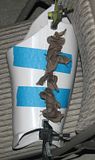
With the thighs now enclosed and completed, it was time to attach the smaller ammo pack onto the bottom right thigh. First up is trimming the paint sticks so that they will go between the ammo boxes.

Then going slowing, one joint at a time, use a heat gun set on low to warm the plastic that is being squeezed by the paint stick clamp. The entire piece needs to make a “U†when completed.
Now just get your cap rivets (aka speed rivets) and attach the ammo pack to the right thigh. Make sure you do one side at a time so that your predrilled holes will line up. You will also notice a clamp and some blue tape on the center joint. I am using E6000 to glue that center portion to the thigh to cover up the seam on the thigh itself. This also keeps the ammo pack from shifting while I walk.
Wow, that last picture was picture#100 in this build….Hope I’m taking enough for all of you! LOL
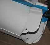
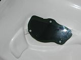
Now to move on to that infernal knee plate. After I used some manual bending to get it to fit better on the top of the left calf, I used Magic Sculpt to fill in the boxes on the back. This will give me some extra surface area to attach the plate to the armor.
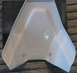
Here is a front shot of the completed plate, ready for gluing. Notice the slight curvature on the bottom of the plate. This has helped me with attaching the plate by providing more contact surface to the armor.
First phase of gluing is shown below. I attached only the center of the plate and let it dry for 24 hours. I used heavier duty spring clamps here, and blue tape to hold it in place. After this had dried, I used the same clamps to finish the outside and inside joints. I forgot to get pictures of this, but will look to add a completed picture of the attached plate. I am not 100% happy with the results, but it should be sufficient for the build.
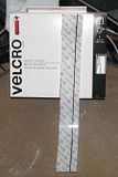
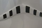
Going back to the shins, it was time to install the velcro. I am using 2†industrial velcro for this. First up was to measure the width of the joint and then mark that on the back of the velcro with a Sharpie.
I then could install the velcro onto the shins. I put the hook on the armor and the loop on the inside of the cover strip. This is the completed installation on the left shin, prior to gluing in the knee plate.

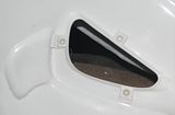
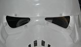
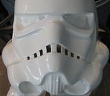
Back to the bucket and it is time to cut out the eyes. I first traced where I wanted my cut lines to be and then started cutting out sections so that the ABS would snap and score without damaging the eye socket.

Here are the completed eyes, all sanded down of course.

A quick test fit with the back cap. I’m liking it very much so far.

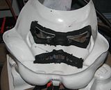
For my lenses, I will be using a three point screw installation. I built up interior pads using scrap ABS, with the top layer having a hole just large enough to accommodate the nut for the attachment. I am using computer nuts/bolts that are made out of a synthetic polymer.
With the pads done, I used some cardstock to trace the opening of the eye socket from the front. Adding a ¾†edge around that trace I came up with a template that could be trimmed down on the lens material to fit the opening. Here is the test fit, both from front and back.

A shot of both eye sockets completed with the pads.
Magic Sculpt was now used to smooth out the pads, making the interior look like the plates were designed to be there.
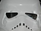
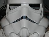
Flat black was then painted at about a ¾†perimeter around the eye sockets and frown. I want to give myself a buffer here so that when the plasti dip is installed, I don’t have to worry about going all the way to the edge of the installation. I can just bleed it into this flat black.
Here is the frown, all painted. It is now starting to look more and more like a TK!
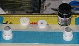
One last bit for this update before I round out my final checklist. I cleaned up and assembled the Mic Tips for painting. These will get two coats of semi-gloss black on the outside only. All interiors will be left as white, including the tips.
Updated Final Checklist:
-
Attach industrial strength Velcro to inward facing joint on each calf. This is the closure method I have chosen to go with. - Add Velcro to boots. Going to use the hooks on the boots and the loops on the inside bottom of the calves.
- For sections of the calf at the bottom not getting Velcro, attach moleskin 1/16†from the edge.
Install 25mm rear cover strip to inner rear thighs.Install thigh ammo boxes to right thigh bottom.Install knee plate on top of left calf.- Install split rivets in left joint of Kidney & Ab plates
- Install split rivet in cod plate.
- Install “Han†snap in right hand side of Ab plate
- Install male snaps in the butt plate
- Glue shoulder bridges to the chest plate
- Make snap plates for strapping.
- Strap armor to fit.
- Assemble Bucket (Cap attached to Front, Ears Attached, S-Trim attached)
- Install Bucket interior. (Lenses, Frown Mesh, Fans, EAS, Complete Electronics connection to external battery)
- Paint bucket. (Tears, Traps, Vocoder, Ears, Interior)
- Submit photo’s for TKID, then EIB and lastly Centurion.
-
-
Outter strips ate sufficient to hold the armor together. Some (like me) use the interior strips to cover burrs and for some extra strength.
That extra flashing on the armor is normal. One you have fit the pieces to you, trim or sand the extra to keep the same lines. Be mindful of return edges that you want to keep (some edges must be removed).
Good luck on your build!
-
1
-
-
Thank you for all the recent comments. Work this week was nuts as one of my imports warehouses needed to be inventoried. This weekend my youngest turns 2, so of course we are at Disneyland.
More work to be done this week, if I have time, a very small update to post this Sunday.
-
1
-
-
You can also go to a local hobby shop or model railroad store to get 1mm styrene sheets. You can use that plastic for your interior strips.
-
For the thighs, the deeper swoop is the inside of the leg, facing the groin.
-
Your best bet for sanding down the resin is a dremel with a barrell sanding attachment. Keep the speed slow and steady so you can keep good control.
Once you get the bulk of the material removed an the piece shaped to your liking, do a finish sanding with fine grit sand paper (220 or 320).
Good luck with your build!
-
Thanks Brandon, have started getting components together for this build, and you have made it very straight forward for those who follow in your footsteps.
I only hope mine turns out half as good as yours has.

Thank you Andrew, I am sure if you take your time and don't stumble in the areas that I did you will be fine. The hardest part of the build for me was getting all the electronics in the custom made counter. If you run across any trouble, feel free to PM me.
very well done! happy to see that another arduino blaster was born

and i should paint mine again following your tips, really like the finish look
Manuel, these are big compliments, and I thank you sir. Yes, I really like how the finish turned out I have already had some comments from friends that it looks like a real weapon. One of those being a US Federal Air Marshal, LOL. Your build was a huge inspiration and if you missed it throughout the thread, I give you all the props for my Phoenix Prop (chuckle).
-
The So-cal garrison has a couple of groups for this. Hit me up with a PM and I'll get you the links.
-
I used the 1/4watt 10kohm as listed in the diagram. I omitted them in error from my shopping list. Those resistors I sourxes from Fry's.Another question for you please.
In your schematic diagram, you are showing 1/4 W 10Kohm resistors on the switches, but I couldn't see them in your parts listing.
Did you use them in the end or use the 300OHM in the list.
Cheers
Sorry for the omission
-
Just a suggestion. Separate the cod from the ab. This will allow you to raise the ab and kidney plate, which is covered by the belt when kitted up.
You can keep the gap closed between kidney and back and raise the back/chest by maybe as much as an inch. That might help address the issues you have.
-
Nice job on the repair Josh!
-
If you need to trim the thighs to fit, the trimming needs to happen at the top. For the bottoms, you can notch the back for mobility, but don't trim off the ridges on the sides and fronts.
-
2
-
-
Put a little away each month for your kit. Designate a budge in order of expense for all the extra's and purchase one to two items at a time (i.e. snaps and Velcro). Start compiling all this up while you do your research into your build. Try not to look at the overall bottom line, the amount is definitely off putting if you are on a budget. Just bite it off in pieces and in relatively short period the "Big Brown Box" day will be upon you.
Don't rush it, family commitments come first.
-
Now while all these pieces were in their various stages of drying, I moved on to the bucket. I know a lot of the community does their bucket first. For me, I think this is a disservice to new builders. The experience I have gained during the course of this build on how to work with the material has been invaluable. I would not have had this knowledge if the bucket was done first and I fear it would have been much easier to make an error that could not have been recovered from.
If you are preparing for your first build and are following along with me, my advice is to save your bucket.
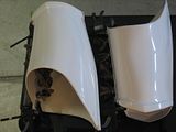
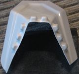
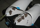
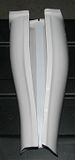
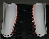
So here it is all the major parts. Face plate, back plate, ears (MTK gives you 2 sets) and my Hovi Tips from Raj.
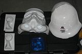
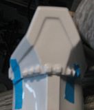
I wanted to start on the face plate, which meant carving out the teeth. I used a Dremel to do the bulk removal. What you want to achieve is knocking down the blister from the pull. I kept reminding myself that only 4 blisters per side were to be removed. Here is an interior shot after I had sanded down the left side.

This is what it looks like from the outside. Look at all that flashing!

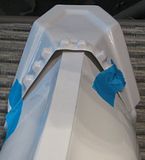
Detail work now starts. I am using a hobby knife with a scalpel attachment, a miniature key file and 800 grit sand paper. The goal is to get the teeth “squareâ€. That is really a misnomer, what you are really looking for is a quadrilateral that has two parallel sides (the verticals). Your horizontal lines need to self-intersect on the horizon, following the curvature of the frown.
Take your time on the teeth, just little cuts with the blade, followed with filing. Once you are happy with the gap you have created, sand from the inside with the paper to create a smooth joint. Here the left side is done and I have moved on to the right.
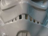
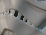
To get a feel for how it is going, look at the gaps you are creating from the inside. The following picture is a good example of the quadrilateral shape that I am going for to create the “squared†off sections.
Here is the outside shot with all the teeth completed. I am very happy with this outcome.
That is all I have had time for, so now it is time to review the checklist, a few items have been marked off. Yay!
Updated Final Checklist:
Trim rear of both calves to fit.Glue on rear cover strips for calves. I am going with 25 mm for that measurement. They will be glued on only the outside portion of each calf.- Attach industrial strength Velcro to inward facing joint on each calf. This is the closure method I have chosen to go with.
- Add Velcro to boots. Going to use the hooks on the boots and the loops on the inside bottom of the calves.
- For sections of the calf at the bottom not getting Velcro, attach moleskin 1/16†from the edge.
Install 20mm interior cover strips to thighs.Trim rear of thighs to fit.Close rears of thighs with a 25mm cover strip that is glued onto both halves.- Install 25mm rear cover strip to inner rear thighs.
- Install thigh ammo boxes to right thigh bottom.
- Install knee plate on top of left calf.
- Install split rivets in left joint of Kidney & Ab plates
- Install split rivet in cod plate.
- Install “Han†snap in right hand side of Ab plate
- Install male snaps in the butt plate
- Glue shoulder bridges to the chest plate
- Make snap plates for strapping.
- Strap armor to fit.
- Assemble Bucket.
- Install Bucket interior.
-
Paint bucket.
Submit photo’s for TKID, then EIB and lastly Centurion.
-
Build Log – 6/29-7/2 – Legs and Bucket
Good progress this week considering I have not had a lot of time to work on the build.
First up are the thighs. First up was utilizing the help of my lovely wife to tape the thighs at their best fitting position. The front seams are square, while the rear seams taper to the shape of my thigh.
The front cover strips were then completed on the front half. Again, these are 20mm in width.

Once the E6000 had set up, it was time to attach the interior cover strips.
After that had dried it was time to trim the rear overlap material to my marked centerline seams. I used tape as a temporary closure to check the fit. If you have over trimmed here, 2-3 mm of the cover strip can expand the joint and keep it hidden. Thankfully my measurements appeared to be spot on as the rear seam runs down the center of the back of my thighs.

During the test fitting I found that there is quite a bite from the thighs, so it was time to cut in some arches to allow better movement. I have not sanded these yet as I will need to do another test fitting to make sure everything is ok. This will be done once the rear cover strips and inner strips have been applied.

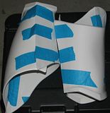
Here is the start of the attachment for the rear cover strip. I am using tape to secure the interior joint. To reinforce that joint wide craft sticks (lounge depressors) are also used.

A combination of tape, magnets and squeeze clamps are used to hold the joint in place. Both sides of the joint are being glued simultaneously. Cover strips here are 25mm in width.
Moving on to the calves; just like the thighs a test fit was done and tape was used to help establish an outer joint. You can see that pencil line in the following picture.
To my pleasant surprise, the raised portion could be trimmed to exactly 25mm. I will use 13mm on the outside for the cover strip joint and then 12mm on the inside portion (facing your other leg) for where I will ultimately apply industrial Velcro for closure.
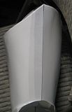
Before I moved on to gluing in the 25mm rear cover strips I wanted to check the knee plate. Ughhh, this is not going to be a fun part to attach.
From the front it looks ok (forgive the blurry picture).
From the inside, again looks good and lines up with the armor lines. I will trim some more flashing away where you see the tape, but this is just testing.
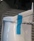
Outside view, again looking good. A little tweaking when I glue the joint will be needed to ensure it lines up with the armor. This is just a poor picture.

Then I checked the bottom perspective, the view from the ground up. Wow…look at those gaps. That just cannot be right.
I went back and looked at all the MTK builds I could find. I even pulled up centurion ATA builds. I just couldn’t see where that gap looks to be as big as what I currently have. Time for a thinking cap session. Considering the topography of this piece (the bubbled out bits), heat bending is going to present a lot of danger. The ABS just has a lot of inconsistencies in thickness. I am afraid that if I break out the heat gun, the thin ABS will warp and fail before I can shape the piece. I ruled out water bending as well. Ultimately I decided on brute force. Supporting the knee plate in the center against a piece of scrap 2x4 I used my off hand to quickly work the ABS in the same motion as you would doing a “score and snap†for trimming. This began to heat the ABS just enough for me to start shaping the part to better fit.
I will add a photo later as the shins are drying with the rear strip, but I was very happy with those results. My plan is to fill most of the bubble bits with Magic Sculpt to give me more surface area for gluing. Phew, challenge overcome.
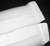
With that said, it was time to glue on those rear 25mm strips to the calves. The following picture is a downward view of the left calf. It is very important that you glue your cover strip so that the Velcro is on the inside seam, not the outside seam.

Both pieces complete!
-
You will be finished this before you know it. More photos please, loved your blaster thread and enjoying your armor build.
Sent from my iPad using Tapatalk
Andrew, thank you for the kind words. Hopefully today's Build Log will not disappoint with the pictures
-
Agreed, testors paint thinner should soften the acrylic enough to remove it.
-
Andrew, Derreck is right. The omhs are the important part. I used lower wattage as the the parts are just smaller and makes it easier to do the final installation. If you go with higher wattage the resister may have a hard time fitting into a small space on your circuit board.


Disney's stormtrooper voice changing mask
in Build Threads Requireing Maintenance
Posted
Flux will also help. Lightly brush the wire with flux then touch your iron to it. This will remove any impurities from the wire, like oils from your hands as Tony has mentioned.
You should be abke to tin without issue from there.