Khazid
-
Posts
370 -
Joined
-
Last visited
-
Days Won
1
Content Type
Profiles
Forums
Gallery
Articles
Everything posted by Khazid
-
I attacked the magazine clip the same way I went after the receiver. I drilled two holes using a 5/8 spade bit. Yes, I purposely cut out the one side. Sadly, the battery is just a hair too wide to sit inside the clip I received so a modification is in order. Once the holes were drilled I took the “eater†and finished boring out the cavity that will go around the battery. Now I can notch the top of the magazine to slide around the battery and start working on the replacement well that I cut out. Pull out the magic sculpt and back to work putting in the details I erased with my modification. The idea here is to get it as close to what was removed as possible. This is a picture of what was completed prior to the filler drying for sanding. On the “clip†for the clip I can install my batteries. These will match up against the zinc plate that was installed in the receiver. I used four Grade N48 1/16†x 1/32†batteries. These were sourced from K&J magnetics. They are super tiny, but have about 1/8 a pound of pull, so they are strong buggers. Not strong enough to mess with the battery though. I’ll put up pictures of the completed assembly once it fully dries. The filler has to set up for 24 hours and then I can sand it down with files/paper to finish the shaping.
-
Several updates to post for your enjoyment and/or comment. I have put in 15 hours of build time to get to this point over the last two days. Considering it is my vacation this week, I wanted to hammer in as much time as I could. Sadly, no build time is open until Friday. My wife has a birthday that needs celebrating, so out of town we go starting tomorrow. First up is modifying the mag receiver to allow for the battery and battery plate to fit inside. I started with a 5/8 spade bit and drilled two holes down the center. I stopped with about ½ inch of material left in the receiver so I could have a stable surface to mount to the barrel. I now took my dremel and an engraving tool I have nicknamed over the year “eaterâ€. This bit chews through resin and styrene like butter. I set the speed to 7 so I could get a good feel for where the bit was and set to work. After an hour, here is where I was at. A little sanding to rough out some of the bits and it was time to fit in the battery plate. I took some measurements and then started on the plate. I am going to skip most of those steps, but after about 10 minutes of straight up hacking with a cut off attachment here is what you are left with. I soldered on new wires to the terminals and then curled them towards the inside and set them with hot glue to keep them in place. To make sure the screws didn’t take all the weight I now floated the front with some 1mm styrene. It took three layers to get it to where it would fit well. I then covered all the edges with magic sculpt. After letting that dry over night, grind down the screw heads and sand the edges to get to this. The battery plate can now be epoxied into the Magazine Receiver. Before gluing I made sure that the battery fit. All was good. I then cut a tiny piece of zinc sheeting, which you can see in the below. This will allow for my magnets to attach properly. Now I could bore out the part to allow for the set screw and then attach that along with the set screw.
-
Thank you for the support and nice comments Wibowo, Pat, et. al. I'm on vacation next week so will start tackling the build on Monday. Only get three days to build as the family and I are headed to Disneyland for a couple of days in the middle of the week after St. Patty's. I already measured the mag receiver and the battery is going to fit just fine in the stock part once I hollow it out some more. The magazine itself is going to need a small mod by adding 0.75mm of styrene to the edge facing the end of the barrel. It was just that close to being perfect. So my first hurdle from a planning perspective is done. Just have to execute that. I feel very comfortable that if I can get past that piece, the rest will just flow. What I learned from Skyone's thread is that patience will be a virtue in getting it all to fit. I don't think TK's have much of that, but I'll find it. LOL. I will do my best to document each step with pictures to post. Updates to come when I have time to post them. I'm already budgeting at least 2-3 months at a clip of 9-10 hours a week to complete this, let's see how I do.
-
Khazid has been an RPG name I have used since the very first dice hit the table back in the 80's playing D&D. I remember searching the name at that time I found a reference that meant "Bringer of God's Wrath", I thought that was perfect for a Dark Elf Wizard. As the years progressed I joined the Beta for SWG (Star Wars Galaxies) and Khazid morphed into a twilek droid engineer. I met some new and dear friends that are a part of The Crescent Order, a gaming group that still exists to this day, though I retired from them back in 2010. So Khazid is always with me, it's a part of me, and for my closest friends; it is the moniker you know me by. Often shortened to Khaz, or Krazy Khaz, it all works.
-
Came home today and had what looked like a brown box on my doorstep. Here are the details of the Phoenix Props Kit. I am super impressed with the details on some of the parts, especially the new scope and power cylinders that Derrek has brought online. Yeah yeah, I am not attaching a photo of the box itself. Rebel spies did a number on it and Imperial censors do not want it released to the public in fear of damaging the reputation of the supply line. I am in communication with Derrek regarding the damaged folding stock, it was the only damage I am not sure can be repaired while completing assembly. It's missing about 1.5" of material. Rebel scum!!
-
Favorite armor building videos?
Khazid replied to AsBlondeAsLuke's topic in Assembly, Mods, and Painting
The Youtube videos on Trooperbays site are great. -
Armour for a larger tropper (not in height but gut!)
Khazid replied to cyberfez's topic in Getting Started - Read this First!
Your best bet is to post your stats (Height, Weight & Waist around the belly button). The vets here can steer you to armor makers to "fit the build" so to say. -
I have had no issues in testing. The LED's fire off fine and are super bright. I was lucky it would appear.
-
Skyone, they are wired up in parallel. LED's wired in that fashion receive no voltage drop. I'll post the link to the article I read confirming that when I was designing the mods to the circuit. Edit Note: Here is the link to the article on LED's in parallel. It pulls a small amount extra current, but that should be regulated by the drivers.
-
Very nice job on that seam. I doubt anyone will see it, unless you point it out.
-
ATA Armor Build_My First TK
Khazid replied to russellr2d2's topic in Build Threads Requireing Maintenance
I just had an image of a flying thigh knocking down a formation. Too funny! -
Chris, right now all I have is theory behind this as I am still waiting on my kit to arrive for assembly. I will approach this one of two ways: 1) Hollow out the magazine receiver enough to install the "battery box". That box will be a styrene (1mm) enclosure that has a modified switch plate for the battery installed and enough room to put in the battery. I am hoping to get the box to be enclosed fully, but still have 5-10% of the battery and plate exposed, to facilitate removal of the battery for charging. The magazine clip would then slide over this "extra" and via compression and magnets, would fit into the receiver, completing the illusion. 2) If the above cannot happen, due to space limitations in the receiver, then my only option is to "explode" the receiver and clip to customize the part. The explosion involves a jewelers saw trimming off all four sides, keeping it as thin as possible to minimize damage to details. Those parts that can be glued to the outside of the battery box, and then magic sculp will be used to fill in gaps and sculpt any details that are washed out by the saw. This will of course require a lot of work, and would increase the size of the magazine receiver and clip. I won't know which of the two approaches will be needed until I get the parts in hand and can take measurements with actual pieces. However; I do promise a very detailed build with pictures and descriptions of what I'm doing to get this all done. I've built this E-11 in my head so many times it isn't even funny.
-
No, he hasn't changed it yet. I believe he was waiting for some of the new molds he was making to be fully finished before he makes the name change. I'll let him speak to that though.
-
arduino: a cheap board for E11 blaster effects
Khazid replied to skyone's topic in Electronics for Helmets / Blasters
Skyone, your thread was the inspiration behind my ANH E-11 build. Your help via PM's, and the work in this thread was so helpful, that I doubt I could have pulled it off on my own. Many thanks! -
Chapter 2 – Phoenix Props Kit With that my new friends, this story must pause. It seems some rebel spies infiltrated the DHL facility in Germany and have caused delay to my shipment. In reality, the carton was damaged during initial sortation and was flagged as such by their OS&D department (Over/Short/Damage). The carton required repacking and was stuck in the facility for almost two weeks before leaving for the states. Ugh. Thankfully, I paid for insurance and tracking on the package so Derrek and I will now be able to sort things out once the brown box arrives at my door. As I post this, the carton is still in transit so no further updates until it arrives. When you can, pay for insurance on shipments! I am going to list some tools I feel are noteworthy to use in a build like this, it is not all inclusive of what I will use. Dremel – Nothing in my hobby experience is more versatile for bashing than a dremel. It can grind, polish, act as a router, engrave, sand, drill, tap. I know several people use them here and you can now put my name on that list as well. It is the swiss army knife of model building, which is why I feel it should be mentioned. Magic-Sculp – This is my filling compound of choice. It is an epoxy putty that will bind to most materials when the surfaces are properly prepared. What I love about this stuff is you have about 10-12 hours of working time with it and it cures in 24 hours. There is no shrink as it dries, and it can be smoothed with water. Yes, water. I buy it in 0.5 pound tubs at a local hobby store (Kit Craft in Studio City, CA), but you can find 1 pound tubs easily on Amazon. I got rid of green stuff, many years ago when I discovered how easy it is to work this stuff with just some basic clay modeling tools. I hope to show off some of its capabilities here as my journey continues. 5 Minute Epoxy – This is my glue of choice for projects like this. Yes, I know people use E6000. But I want a nice solid bond that will work between surfaces of varying composition. My experience with E6000 is that when the bonding surfaces are of different material (i.e. bond plastic to metal) the finished bond is not as strong when bonding similar materials (i.e. plastic to plastic). CA would also work, but I have found it makes surfaces more brittle, which creates issues of wear over time. I have no science to back this up, just personal experience. Flexible Sandpaper – I saw this on a separate thread and loved the possibilities. Especially wrapping it around a toothpick to get into crevices a dremel won’t reach. No more folding sand paper to get into those spots! Can’t wait to let you know how that goes. Then I have a workshop of various tools and gadgets to use as needed to get the job done; precision or brute force to be used with reckless abandon! This is all for now. I will continue Chapter 2 once my brown box arrives. Rebel scum! I welcome all comments and suggestions.
-
Build Plan With the electronics now fully functional, it is time to start figuring out where I am going to put all this within the blaster and accomplish my goal of keeping these items hidden without having to sacrifice too much accuracy. The Battery – I will hide both the battery and its switch plate in the magazine clip, just as Skyone has done. From what I have seen in the Phoenix Prop kit, I will probably have to drill an extra hole in the barrel to run the wiring. If I am able to hollow out the magazine enough, I will use it as stock, reinforcing it with 1mm styrene. For the clip itself, I want it to slide over the top of the battery. This will allow me to use a combination of compression and magnets to hold it in place while trooping. The Scope –This part, which will consist of two decals and 4 layers of clear 1.5mm styrene that when combined will make a stacked sandwich that can be backlit. The backlighting should allow for different tones from the same LED based on transparency of the decals. It will hopefully give the illusion of a three dimensional reticle. I have used this technique in the past when using fiber optics to light up control panels in model planes. If I can pull it off on this scale, it should be very cool when looking down the barrel towards the “business†end of the weapon. I will hide the wiring for the LED by using a drinking straw that will be cut in half. Once the wiring is hot glued to the bottom of the scope and hengstler brackets, the drinking straw will cover the wires. The illusion should be that of a conduit. Yes, I lose accuracy points for this, but my hope is to paint and model it effectively so that it looks like that conduit belongs there. Time will tell how successful I can be with that. Hengstler Counter – Oh this one will be fun, as a good part of my electronics will be hidden here. The numbers for the counter will be replaced with the LED Bar Graph. I will use clear styrene to make a small “window†for the bar graph to bump right up against. To the immediate right of that will be a 2-3mm circle window that will be used for the “Selected Weapon†LED. To cut down on its brightness, I am going to frost the styrene just enough to mute it, but not make it too opaque. Tucked inside the rest of the counter will be the MP3 board and the 3W+3W mini amp chip. This is a lot of wires that will need to go back to the Arduino, so I will put in a small circuit board here to handle the incoming 5V power source, the required resistors, and a common outbound ground to get back to the main circuit. I will have a space issue, so the plan for the counter is to just cut off the front part at the seam and rebuild the shell out of 2mm styrene. The new shell will have mounting screws off of the plate closest to the barrel. The back plate will be hollow at the portion where the counter bracket comes off the scope bracket. I will have to redesign the bracket to have down drops that go right up against the barrel, allowing me to hide the hole I will have to drill for all the wiring to reach the Arduino and the remaining circuitry. Considering how complex this will be, I am going to tackle the scope and magazine clip first. The bracket coming to the counter will not be 100% accurate due to my design, but only a trained eye should be able to pick out my mod, if I do it correctly. The Barrel – The RGB LED’s will be housed in the front, along with their LED drivers and one of the two speakers. The rear will have the Arduino chip, a circuit board to handle the various wiring and the remaining speaker. With all that space needed, I am going to have a problem with getting in a spring. I will work around that challenge by using railroad modeling aluminum rods that I can bend into shape, and then build a façade to install into the rear barrel. This façade will look like a spring, and give the illusion of such, but instead of winding around in the internal circumference of the barrel, these will be individual segments that will give the appearance of the spring being in place. I can then paint it appropriately and glue into place after tacking on some screen mesh to further hide the electronics. Sounds easy enough, right? The Switches – I have to plan for 4 switches, so here we go. Switch #1, the trigger, that’s easy, put it with the trigger in the grip. Switch #2, I need a place for the “Weapon Selector†to go, hmm, after researching I am going to go with the firing retention screw. I can use some sculpting medium on the top of the Pushbutton and imitate a slotted screw, then install that into the grip that has been drilled out. Switch #3, where do I put the “Reload†button? Skyone’s build had this in the cocking handle location using a DPST switch. I was going to go the same direction, but was worried about the longevity of the part itself. Then while reading another build thread I saw someone had rebuilt the Hengstler reset button, making it functional with a spring. Wait, reset button, functional, reload. I had my epiphany and thus I will be putting my pushbutton switch into the Hengstler counter, allowing that “reset†button to work as my “reloadâ€. What are two more wires, a button and a resistor in an already crowded box? Switch #4, on/off switch. This one took some time to figure out. Skyone’s build uses a small toggle switch that is incorporated into the magazine base nearest to the barrel. Not bad, but not ideal as it isn’t hidden enough to get to the accuracy level I want to get to. I spent a few days, yes days’, pouring over reference photos before my lovely wife pointed out, “Why not use that switch looking thingy?†I didn’t know if I should laugh or kiss her for the brilliant idea; I chose the latter. So the selector switch it is, but how to pull that off? I started researching via google, looking for different switching methods when I stumbled across reed switches. Brilliant, a little tiny glass tube that is combined with magnets to act as a switch! I already have experience with using very small magnets in modeling that I did for my Warhammer days, time to break those skills out again. All my switches should now incorporate into existing parts on the E-11 and should be able to be hidden to look like standard issue sterling parts. Just have to execute it now. Going to close the chapter on Electronics, my brain hurts. In all, this chapter took 10 weeks of on and off work. Total man hours added all together to get it working was about 20 hours. Most of that time spent reworking the code to meet my personal goals for the project. The rest of the time was spent waiting for parts to come in and the free time to hit my workbench. A personal thank you goes out to Skyone, your inspiration is what drove all the above posts. It is my hope my own ideas have not twisted your original design too much. Without your work, I would have been left with Hasbro guts. Nothing wrong with that, but my “Pew Pew†is just feeling so much more like a true E-11!
-
Here is the picture of the completed project assembled on two breadboards. Everything functions, and the code is working as anticipated. I am especially happy with the “Selected Weapon†LED and the rapid fire E-11 weapon as that code was of my own design. Except for my challenges with getting an MP3 chip that actually would work, and that I didn’t fry on my own, I found the hardest part of this assembly to be the LED Drivers. To get these properly wired I took my SuperBrite green LED and hooked it up to a 9V battery source using alligator clip testing wires and a 10kOHM 5% resistor. I added in an off the shelf LED driver and using breadboard wires hooked to the alligator clips I tested which connection on the chip batch I received was “+†and which was “-“. The trick here is to look at the opposite side of the chip, that barrel shaped part is the capacitor, you want to wire your inbound source of power to the leads loading up that part. Here is what it looks like once you have that done and have soldered down some 22 gauge wire. For me, red is + and black is -. I have labeled the picture as best I could. Sorry that it is blurry. This was the best of six shots of this piece. Need to try and take a better one at a later date. Now the hard part, finding where the Dim pin is located. I used Skyone’s build as a reference, and now hooked up the testing LED into my primary project against the output pin for the Red portion of the RGB Led. I then powered on the project and the testing LED is now lit and on solid. We know we don’t want that, so you now take a wire from Pin11 from the Arduino on your breadboard and begin hot testing the LED Driver by completing the connection against the pins on the chip that are on the back of the driver chip, nearest your power source wires. As soon as you find the pin that turns off the test RGB when the wire is touching that pin, pull your trigger switch. The light should now briefly come on, and then go off. Success! With that pin identified for the driver chips you have, now go through the painful part of soldering a wire to that pin that will be used to go to the Arduino. This was hard for me, and took quite some time to work up a technique to get it done. But, I did get it down and now have three LED Drivers that look like the following. Since there are three drivers, I want to make sure I can follow my wiring when installing the final unit in the barrel. So, for the dim pins I color coordinated them to go back to the Arduino board. I am using a red, blue and green wiring for this. Yes, I know, I am already using red wires for +, and now I am going to use it again for the Dim pin. Oh well, so be it. LOL. Reference the above pic to see where I soldered that wire on the chips that I secured.
-
Parts List I would suggest purchasing a couple pieces of each item, as your project could experience delays if you get a bad part, or like me, accidentally punch down a connection to the positive of the battery, when you meant to punch it down to the ground. Yes, even 7.4 volts will burn up your MP3 chip. I have the burned out part to prove it, LOL! Arduino Nano v.1.3 – I sourced these from E-bay and got a good price on them. I purchased two, and was glad I did when I somehow killed the first one. It may have been static discharge when I was plugging it into my PC to load some code updates, but I’ll never be sure. It just suddenly started going bonkers and then died. Oh well, I had a spare and that one is now ready to go. Kingbright LED Bar Graph – I sourced these from Digi-key. WT5001M02-28P – I had a heck of a time getting these to work for me. Turns out my first source, from E-Bay, was sending me bad chips. So, for my second round of purchases I went through Ali-Express and had much more luck. Very first chip from the new supplier is working just fine. Sandisk 1gb Micro SD card – The MP3 chip can handle up to 2gb, but since Skyone got his to work with the 1gb I went that route. These are hard to source, but I did find the one on Amazon. 3W+3W Mini Amplifier Chip– This little chip is amazing, I just didn’t believe the sound volume that would be possible to get out of it and I was wrong. I sourced mine from E-bay and purchased two of them to be safe. Still have the spare in case of any incidents. Speakers – I got the same ones that Skyone has. They should easily fit in the aluminum pipe that Derrek is using, at least I hope so. If not, I’ll figure it out. They work great, and the sound quality considering the setup was shockingly good. [Editor's Note: 6/9/15 - Due to space constraints, I had to eliminate one of the speakers in the final build. I now only have one, but I did not notice any major loss in sound volume.] M16 1W LED Drivers – The first LED drivers I bought for the project didn’t work, as they didn’t have the same dim pin that Skyone found on his. I ultimately used the exact same source that he has linked on his thread. Once those parts came in, they worked flawlessly. I ordered 6 to be safe as I am not the best when it comes to using a soldering iron. 3W RGB LED’s – I got mine off of E-Bay and am using two of these for my build. One will be put into the nozzle and the other will be hidden in the barrel to light up the interior for each trigger pull. It is important that the style of LED you get has a pin for each primary color (Red, Blue, Green). 6mm SuperBrite LED (Blue) – Sourced at a local electronics store, this will be used as my “Selected Weapon†indicator. 3mm SuperBrite LED (Green) – During the troubleshooting of the components, I used this LED as my “status†light for the MP3 chip. Once I got all the code working, that LED has been relocated into the Scope to light up my targeting reticle. It is not connected to the Arduino; it is just constantly on, pulling directly from the battery. Momentary Pushbutton Switch, normally open 1.5A – I got a pack of 4 of these at a local Radio Shack that was going out of business. There are two of them in my build. One is for the “Reloadâ€; the other is used to toggle through the three weapon selections. Microswitch, wired as normally open 3A – This will be on the trigger, sourced at a local electronics store. Reed Switch, 20AT 1.5A max 10OHM resistance – This will be my “on/off†switch. I sourced these on Amazon as the initial reed switches I got from DigiKey didn’t handle enough current and I flash welded three of them before I figured out what was going on. [Editor's Note: 6/9/15 - This reed switch failed, so I had to switch it out with a standard slide switch to ensure stability in the final build.] EN EL-11 Camera Battery – This is the power that runs the whole project. I sourced these off of E-Bay and was able to purchase two in the same transaction. They are rated at 7.4V 1300mAh. Enough power to run the weapon for hopefully 5-6 hours on a full charge, with light to moderate use. If not, the spare should be able to be tucked away on a pouch somewhere on my person while trooping. 1W 300OHM 5% Resistor – Six of these are used in the build, one for the Selected Weapon LED and the remaining are on the LED Bar Graph. 1/4W 300OHM 5% Resistor– Three of these are used in the build, all for the coded switches (Trigger, Reload, Weapon Select). 1/8W 1kOHM 2% Resistor – Four of these are used in the build, one for the green LED for the scope and the remaining are used on the dim pin wires going to the LED Driver’s. Wiring – I used 22 gauge wires in various colors to do all the wiring of the components with the exception of the speakers. For the speakers I used 16 gauge speaker wires that have heavier shielding. This was done to try and keep signal bleed from going into the speakers and causing a background hiss. I am not sure if running at 7.4v will cause background noise, but I just did it anyway. Misc. Parts – 1mm and 2mm styrene for enclosures, EN-EL1 switch plate for the battery connection, blank circuitry boards (no copper connections) for final assembly, quick connect wiring harnesses to allow for easy assembly and tear down of the weapon for servicing, soldering iron, lead free solder wire, soldering flux, heat shrink tubing and a host of tools used for wiring projects.
-
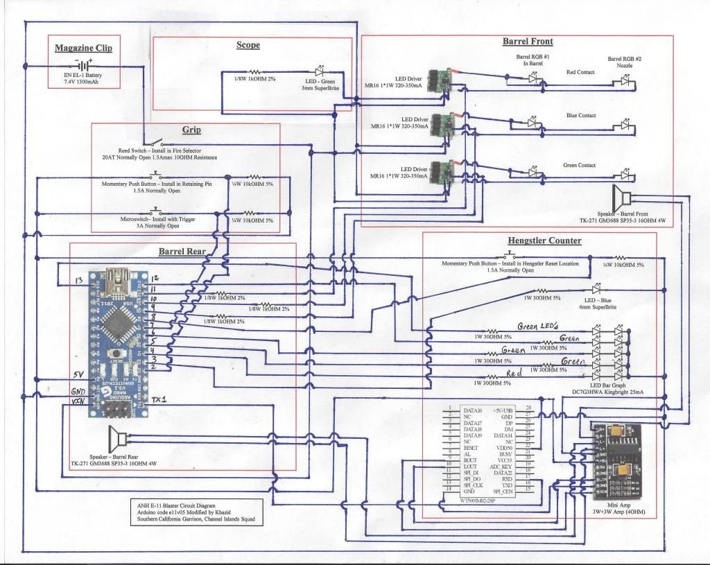
Chapter 1 – The Electronics Please make sure to reference Skyone’s thread on this subject; I am going to avoid all the background on his evolution of the design. Instead, my focus will be on what I have altered for my own vision. Any changes I have made are my own, as are any mistakes that have arisen from those changes. I see no reason why you could not replicate what I have done with the electronics, but you have been warned that I am going my own way with this part of my build. Below is a picture of the circuit diagram that I am using. I am not an electrical engineer, so my apologies if there are errors in the design of this. Here are my deviations: Added a green LED to the scope to light up the targeting reticle. Added an additional RGB LED in the barrel to light up the exposed vents when firing. Modified switches to camouflage their placement in the build to maintain accuracy, but not change their function. [Editors Note: 6/9/15 -- One speaker has been removed, and the reed switch was changed to a slide switch due to design errors]!! I have also made modifications to the code that Skyone has posted as open source. I am posting my modifications as V5 of the E-11 build. This version remains open source, feel free to use it for your own and modify it as desired. Here are my code changes: Removed the additional weapons I do not plan on using. I will only have three weapons: Single Fire E-11, Rapid Fire E-11 (fires 3 shots) and E-11 Stun Mode. Removed the radio mode and random Vader voice at startup, my vision is for this E-11 to be just the gun. Just the E-11 sounds are sufficient. Modified the delay() location in the startup sequence to turn off the RGB LED’s sooner. Modified the weapon selector sequence to reset the LED Bar Graph. This was due to a bug I found in my version not accounting for the ammo level differences between the weapons. Now when cycling through the weapons the code will reset both the ammo count and the Bar Graph. It essentially works like a reload, but I find that minor continuity issue to be better than the bug I had created for myself without this change. Added new code for the status light. I wanted to take that LED and turn into something more functional by alerting the user as to what weapon is currently going to fire as the trigger is pulled. The LED now has three states: Solid – Single Fire E-11, Blinking Fast – Rapid Fire E-11 and Blinking Slow – E-11 Stun Mode. Reworked the code to update comments. I also added comments where they helped me understand what was happening. The sound files I used are Skyone’s. I did use Audacity to modify the single shot E-11 mp3 to get my multi-shot file. This way there is no discernable difference between the sound levels between the two. If you need sound files for your project you can contact him via PM. e11_v05_en.zip

-
The Base Kit I will be assembling a Phoenix Props ANH E-11 Pipe Kit by Derrek. It is my humble opinion that he has advanced the original DVH kit to a point that he should call it his own. The name I have chosen here may not ultimately be what he selects; I just wanted to label it something other than DVH in his honor. The Extra Bits Considering my vision is to go to Centurion with my armor (coming summer 2015), I knew just a simple Hasbro blaster was not going to be sufficient, but I still wanted, well, sound. My initial thoughts were to tear down a Hasbro, and just move the guts into a Doopy Doos. However; I came across Skyone’s design and I knew I was going to follow in his footsteps, so it was time to for some serious electronics studying. I have never done anything other than some basic fiber optics, so this will be a skill to acquire. Build Goal Considering I will be adding full electronics, I am going to have make concessions on the overall accuracy of this ANH E-11. On a scale of 1-10, where a Hasbro is a 1 and an actual sterling with all the bells and whistles is a 10, I will be shooting for a 7, maybe an 8 on the accuracy levels. High enough that it should look screen accurate, but under close inspection there will be inconsistencies. My goal is to camouflage them enough to not hurt my chances of getting that Centurion badge. I just cannot resist a blaster that actually goes “Pew Pewâ€.
-
Since I first joined FISD and started to research my pending TK build I was impressed with the level of knowledge exhibited by the veterans and the innovative techniques constantly applied by the membership to take the hobby further. It is in that spirit that I share with you my ANH E-11 build. I invite you to pull up a repulsor lift, grab some popcorn and Jawa Juice. I hope you enjoy my own personal journey. First, some background on me, I am a hobbyist at heart. I spent many hours in my youth building model kits. Kit bashing is an approach to modeling that I enjoy to this day and I plan to apply the techniques I have learned to assemble my E-11.
-
Read the stickied threads and plan up front an any "upgrades" you want to use. If you want electronics in the E-11, those should be planned up front as well. Print out reference photos, think about when you want to paint parts vs. assemble them. If you get stuck, ask in your thread here as I have learned that troopers definitely help other troopers. Good luck with your build!
-
Only two things this newb can see so far: A) Teeth could be a little more squared off. In the pics you posted they appear to be rounded still. I really like the look of buckets that taper the eyebrow trim in line with the trap above the ear. I would suggest looking at some examples of that and then plot your own course. Your work looks great so far!
-
No problem, I hope it helps.
-
Modeling paints don't stick too well to metal surfaces some times. Try cleaning the surface with simple green. Once dry, buff with a 600+ grit sand paper. Clean with rubbing alcohol. Once dry, prime with a white primer, then paint away.