ejb
-
Posts
27 -
Joined
-
Last visited
About ejb

-
Damn thats pretty brutal! Hope you manage to get it all cleaned up
-
Yet another noob attempting to make a BlasTech E11
ejb replied to ejb's topic in Build Threads Requireing Maintenance
I've been working on the trigger group and have got as far as a test fit on most of the pieces. You will see that the trigger guard is incomplete - I need to determine where the piece that the trigger goes through will end up before making the hole for the back off the trigger guard to fit into. The trigger is going to connect with the brass pin, much like a real sterling The front of the trigger guard will also be held in by a pin I still need to make a spacer bit for the front and back of the group and determine the best way to fit it all together - at this stage i am thinking of 'magic soldering' the pieces to one side and holding the other with pins etc Trial fit of electronics Im not sure it will all fit - the switch and pot are the preferred options (as they 'feel' the best) but I have a smaller switch (not shown) and pot (black / grey thing next to assembly) -
Any Venders thinking about making the new EP VII TK?
ejb replied to PGHtrooper21's topic in Hard Armor (General Discussion)
Regional would be great, as I notice that some countries are not supported (e.g. New Zealand....) -
Very nice!
-
Hi Over on Vern's for sale thread, Mathias posted a link to a MG forum where they discuss the MG34 butt stock material variants http://www.wehrmacht...ad.php?t=487315 1- early in walnutt from 1936 to 1938 2- early bakelite with metal tips from 1938 to 1942 3- bakelite from 1939 to 1943 4- Steel about 1943 5- mid to late war in beech from 1942 to 1945 6- Bunker mount steel butts Post war production (not including repros): -Israeli "dot 1945" contract were with beech butt until 1948 -Norwegian 'whole' buttstocks. -Russian capture 'pointed' buttstocks So for the D19, would there be a 'correct' material? Regards
- 1 reply
-
- 1
-

-
Trying to find template for 1 1/4" pvc pipe for dlt
ejb replied to fuumantroop's topic in BlasTech DLT-19
Link to the templates and see if someone can unzip them for you? -
Yet another noob attempting to make a BlasTech E11
ejb replied to ejb's topic in Build Threads Requireing Maintenance
So a bit of a lack of progress - I've just moved a house (yes I typed that right, the house moved, not me...) I finally re-started on the receiver - got the holes drilled and started on the ejection port and bolt slide cutouts. I do like the incentive (or is the pressure) that a WIP thread provides.. I've also ordered a scope from Blue Snaggletooth and a Magazine from Felice so looking forward to getting those though I only give the Mag a 50:50 chance of getting past NZ customs :-( -
Yet another noob attempting to make a BlasTech E11
ejb replied to ejb's topic in Build Threads Requireing Maintenance
Ahh, now I get it - well I guess it would not have worked even if I had keep the two sides joined. I think the Al solder will join the middle / folded over piece well enough - it seems strong enough with the bits i have done so far. The piece I started for the trigger control group is a fail, so will be starting that one again. :-( I want to have the trigger group made up before joining the grip panels to the receiver to make sure it all works together (plus I have to man up and start drilling holes in my last piece of Al tube....) -
Yet another noob attempting to make a BlasTech E11
ejb replied to ejb's topic in Build Threads Requireing Maintenance
Thanks for the compliment - it maybe a little be premature... I thought that the trigger control 'notch' was supported by the hole in the receiver? Maybe someone with real Sterling experience can confirm. Either way I will be adding a piece of Al (probably 6mm thick) to join the two sides of the butterfly. I choose to do it this way so I can control the gap better. It may well not work, coz I am kinda making this up as i go (and so far have messed up more bits than I have successfully completed. Part of the reason I am trying to make all the pieces is to try fitting them together before drill the key holes etc. -
Yet another noob attempting to make a BlasTech E11
ejb replied to ejb's topic in Build Threads Requireing Maintenance
Thanks and no problem, you looked like you needed something to do I decided to re-create the front of the template anyway and have stuck that to my last / second piece of Al tube. (the first piece is now a, er, um, aaah, "a test piece???") And also started on the Trigger Plate / Grip Bracket - I did decide to make this in 2 pieces as it will allow me to get both halves the same and give a little flexibility in the size of the gap (in case my trigger group ends up a little narrow or wide) -
Yet another noob attempting to make a BlasTech E11
ejb replied to ejb's topic in Build Threads Requireing Maintenance
Awesome! Thanks for that Hmm, I've seen those but never thought of using them for bending! I might have to get a pair or two (never have too many tools, right??) -
Yet another noob attempting to make a BlasTech E11
ejb replied to ejb's topic in Build Threads Requireing Maintenance
Pictures are always appreciated. Mainly focused on the trigger group itself, how it hangs together and the shape of the bottom piece that the trigger goes through. The other question I have is the holes in the receiver - the template from 'the best templates in the world ever' thread seems off to me - in that the offset holes do not seem to be evenly between the others above/below - is this correct? i.e a doesnt equal b (excuse bad MS Paint image) is this a template error, my bad eyesight or true to real? -
Yet another noob attempting to make a BlasTech E11
ejb replied to ejb's topic in Build Threads Requireing Maintenance
Thanks - can't wait to see how you do it. From my research I don't think the template is correct (i.e. it doesnt look folded from one piece to me) I think I will do 2x sides and 'magic Al weld' them to a thicker piece for the front. But plenty of time for me to learn from someone that knows what they are doing!!! -
Yet another noob attempting to make a BlasTech E11
ejb replied to ejb's topic in Build Threads Requireing Maintenance
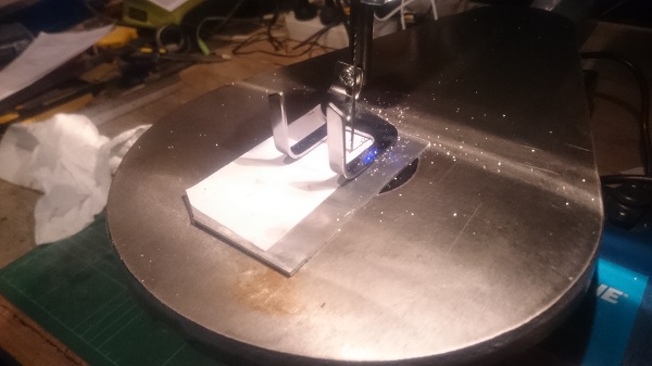
Here the photo of the rough cutting of the first trigger group panel - still a lot of clean up to do... -
Yet another noob attempting to make a BlasTech E11
ejb replied to ejb's topic in Build Threads Requireing Maintenance
Thanks all for the positive comments I'm definitely a noob - this is the first time I have done anything like this (well since I was very young) I'm keen to put together a kit as well. I'm picking the kit will be my accurate blaster, and this will be, er, um a learning experience.... I have a few different thicknesses of Al 1mm, 2mm, 3mm and 6mm (which is prolly 3/64, 5/64, 1/8 and 1/4 in parts of a toe? footlet??) Small update... I bought a new tool!! Looks a bit like a sewing machine, but is waaaay easier that trying to cut with a hacksaw :-) With that I started on the Trigger Group panel (I now have a rough cut out of one side...) - but I think I have used all my photo upload allowance, so photo will have to wait until I find somewhere to host the pictures....