


Dax Corrin
-
Posts
33 -
Joined
-
Last visited
Content Type
Profiles
Forums
Gallery
Articles
Everything posted by Dax Corrin
-
A sad day for FISD Our dear friend Terrell Reber
Dax Corrin replied to Sly11's topic in Announcements
Buckets Off. -
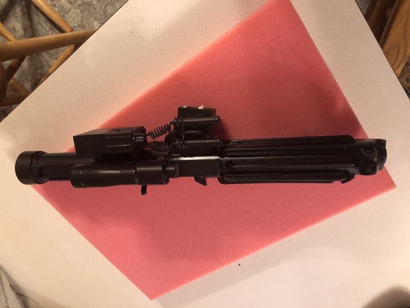
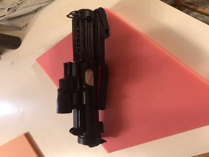
After giving the black paint plenty of time to cure, today I hit the last of the blaster with matte clear paint. I had hit part of the back and the folding stock already but had to re-paint some of the black of the end piece after the clear glued it to the cardboard I set it on to coat. :( Tonight the whole blaster pretty much got hit again, thankfully with NO paint wrinkling. That is a huge win alone. I removed all the tape and it looks really good but like a new blaster not one that has been weathered.
-
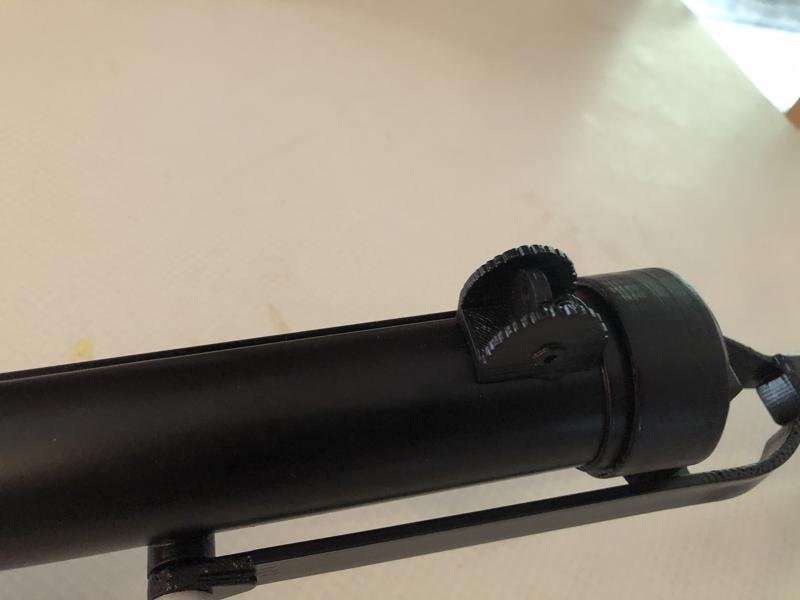
And I removed and rotated the bayonet lug to it's correct orientation.
-
Roger, I'll fix that. And, if you have heard Anthony Bailey's sound chip, that's what it sounds like.
-
Maybe it won't allow any more pics at all. I've exceeded my allowable uploads. Scanning the rest to Imgur and linking. Let's see if this works... Edited Yes, it worked. I added my TKID 12485 to the counter and a clear plastic cover. I'll fill in the chipped paint on the folding stock screws and then mask off the speaker holes scope and LED openings before spraying matte clear on everything to help protect the paint. Works great sounds pretty good and looks pretty decent but unweathered as I don't have those skills.
-
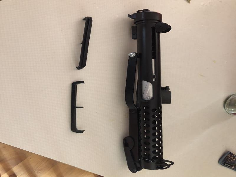
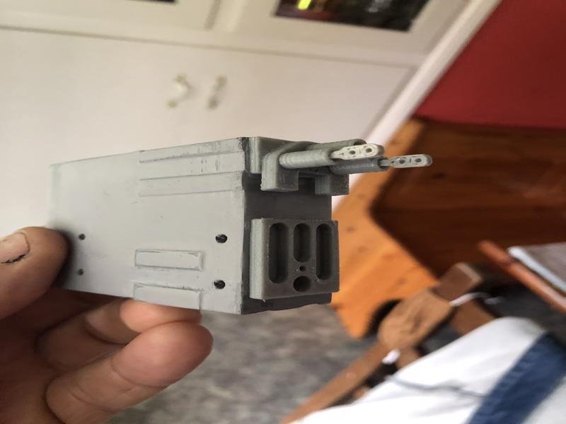
OK, sometimes a big step backwards is needed for a giant leap forward. I think Val Kilmer said something like that in "Real Genius". I managed to get the speaker and chip both in the magwell for testing, not final fitting and that was good. Still couldn't put the magazine in and turning the switch on and off requires needle nose pliers due to limited space between speaker and chip. Then had a failure of a wire at the power (charge) plug and pulled it all back out. Discovered I had gotten super glue on that plug, so it wouldn't come back out. Also the pigtail with the status LED comes out of the wrong side of the board, but having been designed for a larger blaster I can't fault the builder for that. I had to remove the body of the plug for the pwr port, and I soldered the charge plug wires directly to them both and shrink tubed them, then bent them 90 degrees for more clearance. I also shortened the pigtail for the status LED (which is hidden and only seen when turning on or off or charging) and flipped it to the other side of the chip (to component side) but got the red and green wires backwards so when green is supposed to be lit it's red and vice versa. It's not visible to anyone but me and I'll know so not a big deal. I also ground off one of the mounting tabs as it was preventing the magazine from closing. Now the speaker is in, the chip is in and both are glued in place and everything works. Looks like I'm limited to 3 pics per post based on size. More to come in next post.
.JPG.d7cee3bd7eabb396ea03d8a9ca7d5623.JPG)
.JPG.88d7b3992bc154609fafd14a754a507e.JPG)
.JPG.58dac2369d245a82fcc831c3bb8dae0c.JPG)
-
Hengstler counter is also 3D printed and not hollow. I may see if I can shoehorn the speaker in before the sound board but not hopeful... Audio jack to my amp is a possibility, would have to see where I could tap into the speaker wires and discreetly mount the jack. EDIT: I'm hoping a slightly smaller speaker might actually be a better speaker too.
-
I have completed the trigger assembly and it's 2 switches work nicely. I have test fitted and glued it on. Due to the limitations of the pieces I had, the switch to change from stun to kill is basically upside down. I am not happy with the existing speaker, it's too big and hopefully something with a smaller diameter will fit and sound better. I have stuffed the battery the sound chip and all the wires into the barrel and magwell. the charge cable, it's plug and the power/charge light will reside in the removable magazine which is also where I'll access the power switch. Both red and blue LEDS still work at both ends of the barrel after all the jacking of the wires I had to do to wiggle everything into place. The sound chip barely fits, it's designed for bigger blasters with more room in it's defense. Looking for a 1" 2W thin speaker to use, the 1 1/2 that came with it along with the sound chip are just too much to fit in the magwell together and it's the only place the sound chip will fit, too wide for the barrel. More to come, very close to being finished.
-
I realized to add that I had to open up the hole in the bottom of the barrel a little at the back to accommodate the 2 additional wires coming out of the trigger assembly where they did, not a big deal but clearancing was needed.
-
Successfully glued the trigger housing together without gluing any moving parts together. Have sanded and attached the trigger and grip to the barrel, and waiting for that glue to cure. Glued one end of the trigger guard in place as well, it's kind of springy so I'll let the first end dry and then glue the other end and secure it in place with tape until it dries. I'll likely carefully mask off some parts and hit some of it with a bit more matte black then set aside for full paint cure before giving it the final matte clear coat that will hopefully help keep the paint on coming in and out of the holster. Getting close.
-
The point of "No return" has arrived, and I've glued the two halves of the trigger assembly together and it's clamped for an hour or so. There is a screw that goes into the trigger pivot post but the hole is oblong and a couple of slices of the post broke off while I was gently trying to insert the screw. I glued them back on and will gently drill out the hole once the other glue sets. I found that the battery would not fit either in front of or behind the bolt inside the spring like I had hoped. I got rid of the holder and directly soldered the positive wire to the top of the battery. No solder would adhere to the negative end of the battery so I used the connector from the holder and tightly electrical taped around the entire battery to prevent shorts and to securely connect the connector and it's wire to the negative side of the battery. The tape is black so it will help hide the battery inside the slot that the cocking lever slides in. Still won't quite fit in front of the bolt, but fits nicely into the spring end now. I drilled the hole through the center of the bolt to feed the plug and wire though and have added another coat of silver to the bolt.
-
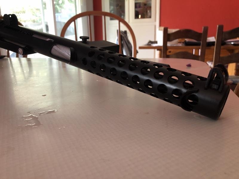
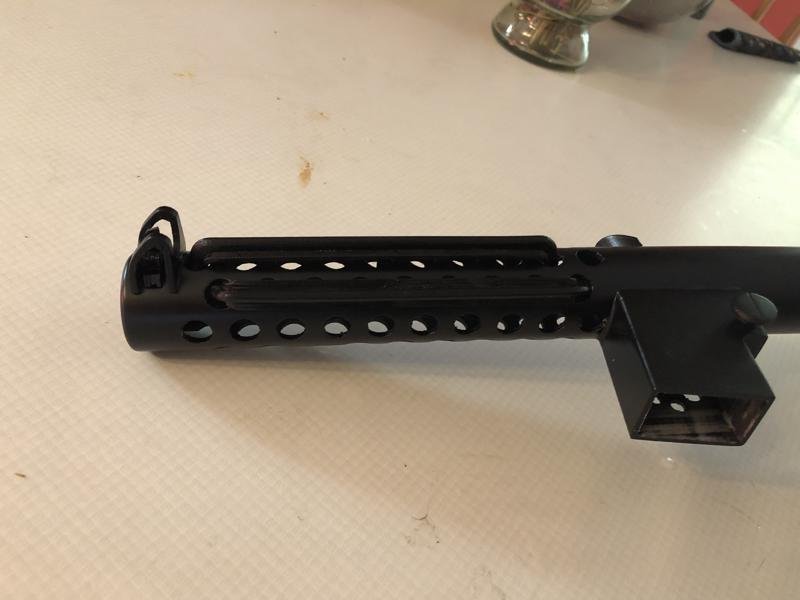
Finally, some pictures. Not a good photo taker. The plugs seen in the magwell are for the red and blue LEDS in the end and bolt sides of the barrel. The sound board and speaker will go in the magwell once the matte clear is applied in another couple weeks' time once the paint fully cures, I do not desire any wrinkling of paint. Modifying the original stun/kill switching was a challenge as I need to make both the switch operate and have it all fit inside the trigger housing. I have figured out where to mount the switch, and will hot glue it in temporarily to make sure all fits together once the paint dries on this side of the trigger housing. Main trigger and it's switch are on one side, the stun/kill switch and it's actuator will be mounted on the other half. Then trim the trigger guard to fit. EDIT: The picture resizer made the pictures kind of wonky. Apologies.


-
I had to paint the 2 new selector switches. Looks like it will work nicely to select stun/kill. I'll hot glue the switch in place on one side and test fit the entire assembly together before gluing and clamping. Looks like I won't be able to add a separate spring for the trigger, no place to put it that will pull in the correct direction. I will thin the area that presses against the plastic spring so less pull needed and less deflection to depress switch. I have admired your work from afar, Glen. A couple of officers in my garrison have your sidearms with the moving barrels, very nice!
-
My friend has already printed me 2 more selector switches today, one for me and one for the cat. I said Frak the cat! Anyway, now I can put together that side of the trigger area later tonight.
-
I firmly believe one of my cats stole the outer switch piece that I had painted but not yet puzzled out the stun/kill selection switch mock-up. I think I have that figured out now but now have a friend printing up a replacement GR-5 piece. Will likely have to modify it's "clocking" to get the internal pin GR-6 to swing where I need it to and the outer switch to be pointing where it needs to. Will temp the switch in with hot glue to one side of the trigger housing, the trigger, it's switch and plastic spring are on the other. I'll be able to get both sets working before mating them together permanently. I'm also going to take an ink pen spring and cut it in half and use for both the trigger and the selector switches so I don't have to depend on printed plastic spring for the trigger cause once it's glued together...
-
I won't be doing the double laser diodes, I just have 2 red and 2 blue LEDS mounted in muzzle 1 each and some shine down at bolt area red/blue also depending on sound selected. My years in US Navy helped train me for soldering and some mock-ups including flashing LEDS in my Gunner helmet and self-made fan kit both run off rechargeable 9V batteries. Pics coming soon, need a decent place to take them.
-
I found my other soldering iron, and finished tying the 2 pairs of front and rear barrel LEDS together, then trimmed the LED holder to fit where I had melted some internal structure to accommodate the sound driver board. All 4 LEDs work together in pairs red/blue as they should. Marked the plugs so I can plug them into the sound board correctly when the time comes. Will likely need to wrap the battery in something insulated and black to hide it inside the bolt spring, and drill a hole through the bolt to feed the battery lead into the magazine area through. Probably will leave the charge port loose but insulated inside the removable magazine area for charging when needed.
-
My soldering station sadly needs a new heater and tip. I was able to connect the second blue LED pair, but the red 2nd LED pair solder joint broke loose. I have another cheaper iron around somewhere but haven't found it yet. I've been working on melting some of the internal structure inside the magazine well to make room for the sound board and the speaker. I still have to reach the power switch too. I think I've made room for sound chip speaker and access for the switch. I may remove the LED that indicates power on as it gets in the way. More to come.
-
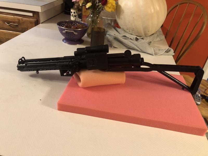
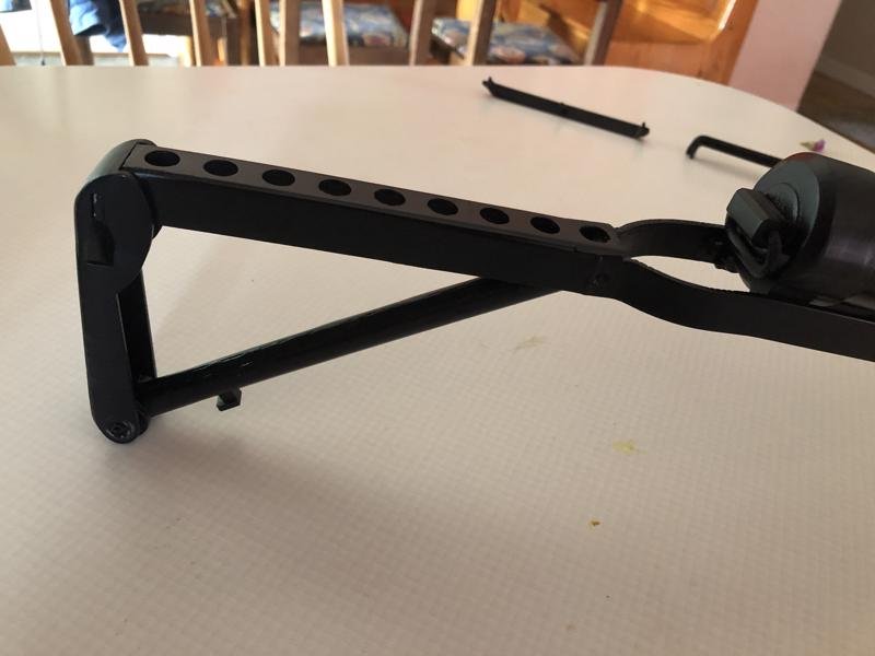
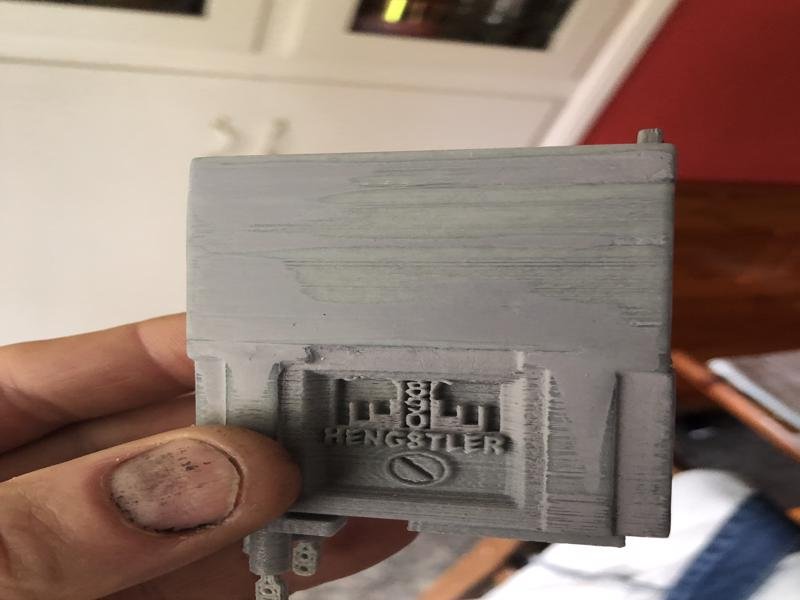
I have successfully converted the common ground 3 wire 2 LED set Red/Blue for the breech pair of the Blaster Master kit and so far have paired the 2 red together. The 2 end of barrel LEDS look nice. A new challenge is locating the sound/LED controller and the battery inside an E-11 blaster. I still have to locate a second switch for the stun/kill selector inside the trigger housing where the original selector as well. The sound/LED controller is fairly large and locating it so it can be turned on and off and have room for the speaker and battery remain to be solved. The manual bolt cocking will likely need to be restricted. Will look into placing the battery inside a black insulated cover behind bolt inside spring. Much to work out electronically. I have added the wires from the Hengstler counter to the power cylinders and a TINY bit of silicone lubricant on the spring and pivot pins for folding stock makes it move and hold together much better. I will let it sit for several days before giving it all a coat of satin clear coat to protect the satin black. I'm just not certain I could do a good job weathering so it might be "new issue".
-
Anthony's sound/LED kit uses common power, switched ground. The BlasterMaster used common ground but through a selector switch that isolated the grounds, so any time I plugged the 2 Blue and 2 Red BlasterMaster LEDS in at the same time they all lit up no matter what mode stun/kill.. It's cool to have a red and a blue at both the end of the barrel and at the breech which is the BlasterMaster idea so I'm retrofitting the Blastermaster LEDs to provide common power through the resistor for the breech LEDS, and using the provided AB LEDS for the barrel end LEDS. So far have the barrel end LEDS working and glued into place, and the barrel tip and Allen screws in place. Will tap the second LED set for the breech area in and still want to get a better speaker. Have some ideas for the selector between stun/kill so it won't be visible. Likely will place charge port behind magazine so just remove it to charge the battery. No more pics yet, but progress is being made. Still puzzling out the trigger as it doesn't seem to work based on the picture in the instructions. Will likely add a spring and epoxy the trigger switch in a place where it doesn't interfere with operation of stun/kill switch and has good "feel". This has been fun and it looks so much better then the cheap blaster I was using. Might take the little blaster with me to let kids hold when permitted and parents approve.
-
It already looks better than the Disney Parks blaster I use if no one objects. Much more detail. Will carry Crazy Glue with me in my kit in case bits want to pop off, that struggle WILL be real.
-
The artificial Allen head screws on the underside of the scope rail to barrel brackets interfered with the scope rail attaching to the barrel properly, so they are gone. I also ground down the heads of the real screws I'm attaching the brackets to the Hengstler counter with, so they don't rub on the barrel. The existing LED/sound chip wiring seems to be backwards on the sound selector switch, but I won't be using that portion. Will need to locate both the charge port and the selector switch for stun/kill sounds somewhere, and the speaker that came with the original kit is not very good. I'll get a better speaker that is the same size. More pics coming soon.
-
More time spent sanding but it will never be perfect. A more modern 3D printer with these files would do better. I used real screws to attach the Henglstler counter to the scope rail angle brackets. Might end up replacing super glue with real screws on the underside of the scope rail to the scope through the Hengstler brackets as well. More likely to survive some abuse with real screws. Started messing with the electronics for the trigger assembly, but not going to use the existing kit, as it sounds like sh*t. Anthony B's kit will be installed, as all I want is lights blue and red and sound stun and kill. The extra stuff like the scope display is cool but more $$.. Everything is looking good but will allow 24+ hours for paint to dry and harden. I am so antsy to work on it that I've messed up some of the paint by not letting it dry thoroughly. More pictures tomorrow Pacific time.
-
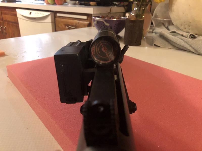
And as promised, a few pictures. 600 grit wet sandpaper is a personal friend of mine. Spent some time on the magazine and then realized it was the under side, so more work on it, along with the work to remover the lines from the bottom. Folding stock works nice. Will likely work some more on the end cap, it still has lines. Hengstler counter still needs work on line clean-up and joint filling. The reset button feels like a reset button when you press it. Ran out of satin black Krylon, need more. Working on the scope and the printed out reticle option, the glue is drying on the small end.


-
Not a lot of pictures yet, will take some today. Much progress and a couple of setbacks but I overcame them. The stock lock that holds the folding stock to the barrel had the pin break off. I drilled out the lock and installed a new plastic pin in it, then adjusted so it holds the stock closer to the barrel. The folding stock shoulder rest also tended to droop under it's own weight. I discovered the locating pin that you use to glue the magazine holder to the barrel and then discard fits into the folding stock tube, thus making the spring "springier" that holds the shoulder rest up against the folding stock. Nice. The sound leaves much to be desired, have ordered Anthony B's sound kit and retrofit it in. I have also painted the stock and barrel and some other pieces with a satin black coat. I am not a skilled weatherer so that is a challenge. I accidentally epoxied the folding stock pivot pin to the wrong location but discovered it and removed before the epoxy fully set. Pics to come after I clean up a place to take them.
