


dm101
-
Posts
138 -
Joined
-
Last visited
Content Type
Profiles
Forums
Gallery
Articles
Media Demo
Posts posted by dm101
-
-
Thanks guys-
I spent a lot of time (at work) thinking about how to improve the Doopy’s Hengstler.
I thought this was the less painful idea I came up with. (you DO NOT want to see my other ideas, very complicated and $$$$)
Craig
dm101
-
MODIFICATIONS TO RESIN PARTS-
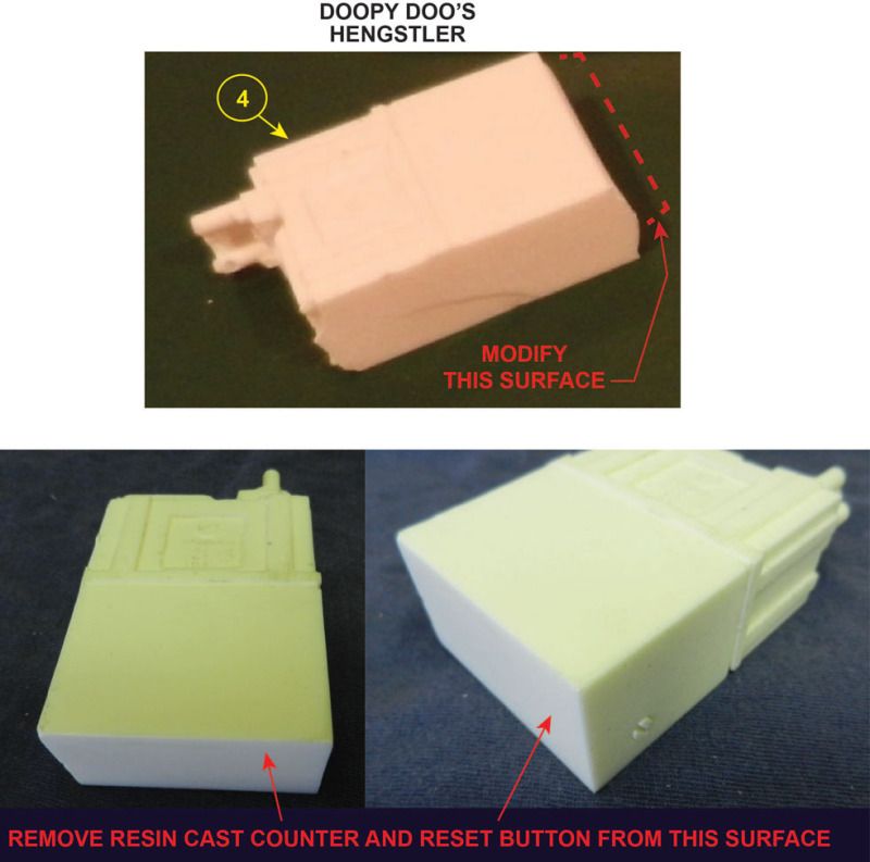
Item #4 HENGSTLER COUNTER
Remove the bumps on the Doopy’s resin cast that represent the counter and the reset button. (sorry I deleted the photo of the Doopy’s resin HENGSTLER before I made this instruction) I used a belt sander with a coarse belt to do the big work, then switched to a fine belt for the finish work. The goal is to have a flat smooth surface.
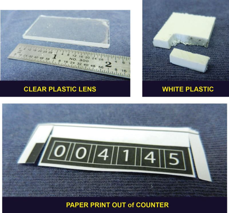
1. Make a Clear Plastic Lens- I used a sheet of 1/16†thick clear plastic. ( I bought this at Lowes) Cut out a rectangle the size of the HENGSTLER face (approximately 1†x 2â€).
2. I had some scrap 1/8†thick white plastic. I used this to make a reset button. The approximate size was 7/8†x 1/4†x 1/8â€.
3. I used my computer and Adobe Illustrator to make the counter. I printed it out on a laser jet printer. I then cut it to size.
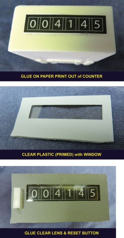
4. Take the printed paper counter. I used rubber cement. Glue printed counter to face of HENGSTLER.
5. I line up the clear plastic lens and carefully marked the area for the clear section with tape. In the photo is a picture of the lens with only the primer coat.
6. I used E6000 glue and glued the clear lens to the HENGSTLER face making sure my clear lens window lined up with my printed counter. I chose E6000 glue over AC or Super Glue because Super Glue can make some types of clear plastic fog up. Next glue on the reset button.
7. I went back with the belt sander and trimmed up the edges after the glue set.
-
The white wires are from my junk drawer of left over house hold stuff. I think they were the wires left over from my garage door openers sensors. They are 2 wires together, but a little cut and pull they separate easily. They remind me of cheap speaker wire.
The black wires are too heavy. (of course) They are also left overs. They are Romex 14 gauge. This type of wire is found in your wall for lights, outlets etc… (if your going to cut wires out of your wall or your neighbors walls…make sure the power is off. It really hurts if it is on.

Maybe the best is a solid thin wire, not multi-strand. Automotive wires might work good too. Lots of cars out there. Lots of auto part stores too.
Oh yeah use your handy sharpie pen to wrap the wires into coils
Craig
dm101


-
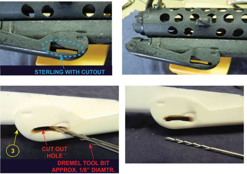
MODIFICATIONS TO RESIN PARTS-
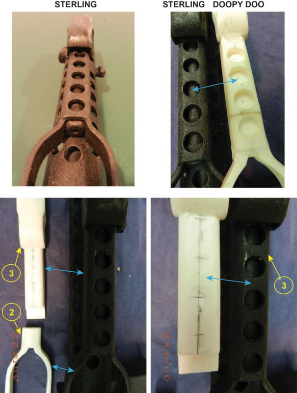
Item #2 and #3 FOLDING STOCK (front and rear)
I cut out the dimples and the open slot on the Doopy’s with two tools:
**The Dremel and the cutting bit (approx. 1/8†diameter)
**A drill with a Forstner bit
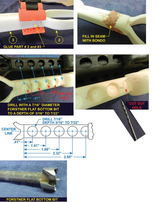
1. Glue part # 2 and #3 together.
2. You can fill in the gap where the two parts come together now (I used Bondo) or you can do this before you begin to paint.
3. Measure the holes to be drilled. (see drawing for spacing, and starting edge to measure from) The Sterling holes measure .42†diameter. I could not find a flat bottom .42†diameter drill. I used a 7/16†Forstner bit.
4. The partial hole under the folding stock butt plate was tough to do. I carefully used the Dremel and the cutting tool bit. (Plus Bondo when I slipped and cut out too much.)
5. The Forstner bit has a pointy pilot tip. I had to fill in the pilot holes with Bondo.
-
Verry nice indeed.
SORRY about copying your entire post.
I tried to do it as a quote thing...I am still learning

You guys do GREAT work
-
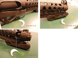
The 2 cylinders sets I got from Joerg, the one with dual small capacitors (left) and the one with 3 holes (right). In the one with the 3 holes I added the capacitors I received from Rob after painting them, they are just attached with their wires and no glue or anything else, so if I want to reposition them or take them off, it can be done in 3 seconds. The entire ensemble is connected to the blaster with 2 flat and powerful rare earth magnets (glued to the cylinders and painted black), thus I can exchange between the two options and also change the position of the cylinders if want to:

LOOKS GREAT-
One question where did you put the wire of the capacitor?
Do you just have them hanging over the edge, or did you drill a hole in the base and tuck the wires in to it?
Craig
-
OK so on my planet we have very short days compared to Earth.
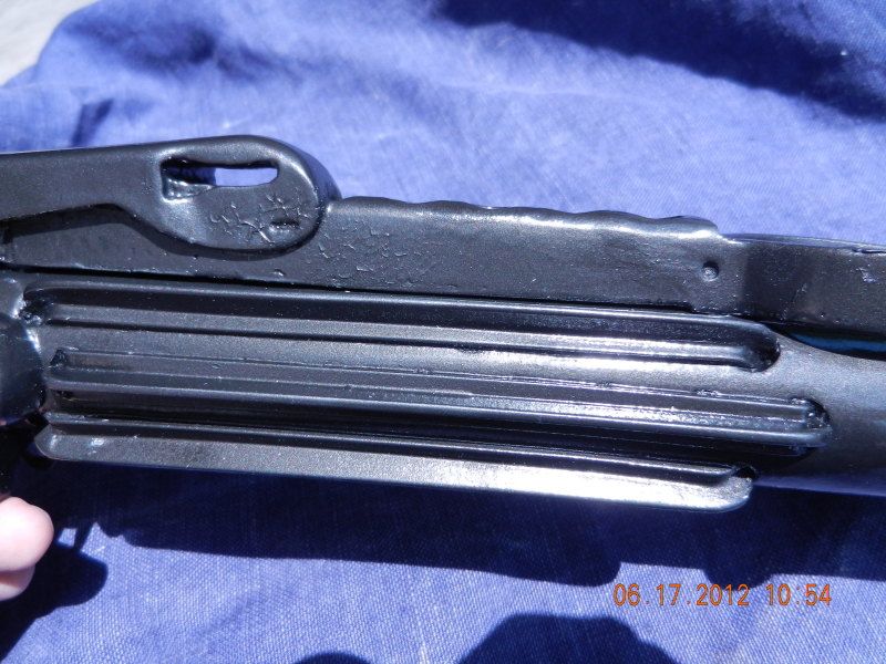
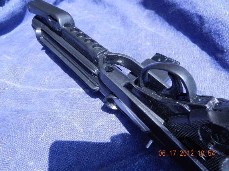
I was able to take 2 photos of my build with the folding stock mounted.
I also double checked my Sterling and same deal. You cannot see the bottom holes with the folding stock folded.
The Dooppys resin barrel is extra thick. So you loose a lot of detail. Youl would actually see the barrel inside the heat sheild or guard. The walls of the heat sheild or guard on the Sterling are thin. Like 1/6" plus or minus 1/32" or so.
I was considering making a barrel for inside my Doopy's build, but opted not to. Maybe on the next build.
Hope this helps answer your question.
Please ask more questions.
-
YES you are correct. ALL the optional holes I show are open in the real Sterling.
I opted to not drill them out. This is only my opinion, and a deviation from the extra details I am doing on my build.
Give me a day and I will take a photo of the blaster with the folding stock installed. My opinion is you do not see these holes.
"I think" if you looked at the blaster from a narrow angle and were really close to it you might see a bit of these holes.
Why did I drill out the next hole in line on the Doopys? I plan on using that hole to aide in mounting my scope rail. ( I have not created the build images for that step yet. Standby)
-
MODIFICATIONS TO RESIN PARTS-
Item #8 FRONT SIGHT
The resin Front sight needed some work.
I used my Dremel tool with a cutting bit and 2 or 3 other Dremel bits to do all the cutting.
This is all optional. Do as much or as little as you like.
1. Cut out the sides of the sight. (2 places)
2. Cut out the small vertical rectangle on the bottom of the sight. I used a 1/16†wide flat nose Dremel bit. You only need to go in to a depth of 1/16†to 1/8â€. (2 places)
3. Drill in a 3/64†hole as shown in the DETAIL drawing. Go to approximate depth of 3/32â€. (2 places)
4. On the top of the sight. Drill a 3/32†hole all the way thru the sight. This hole is for our front sight blade (in my case a roofing nail.)
5. I looked around my garage and came across a box of roofing nails. They were about the right size I thought. I cut off the pointy end. I used a pair of tin snips and cut down the head to the square shape you see in the picture. I used my Dremel and some hand files to file the roofing nail down to the shape of the front blade sight.
6. Not shown ( I deleted the photo) I cut a shallow pocket on the underside of the resin front sight so my roofing nail head would be recessed and be out of the way when I glued it to the main barrel.
7. The front sight blade sticks up about 3/16â€. See the detail drawing.
8. Push roofing nail into 3/32†hole and glue.
-
MODIFICATIONS TO RESIN PARTS-
Item #1 MAIN BARREL (muzzle)
I have seen this on many people’s builds. Everyone has done a great job. It’s a great simple modification that goes a long way. MY 2 cents.
The 2 blobs of resin on either side of the main barrel are supposed to be socket head cap screws. The resin did not do to great of a job replicating this detail. It’s an easy fix.
You may need to flatten the blobs or punch a starting or pilot hole so you can drill without having your drill bit wander off it’s mark.
1. Use a 3/8†drill bit and drill out the 2 blobs to about a depth of 7/32†to 1/4" (depends on the screws you are using)
2. Use the same 3/8†drill bit and drill out the main barrel.
3. Take two 1/4-20 (or 1/4-28) Socket Head cap Screws. Cut of the screw heads an pitch the threads.
4. Glue the screw heads into your newly drilled holes on either side of the barrel.
Looks better than a blob of resin.
-
MODIFICATIONS TO RESIN PARTS-
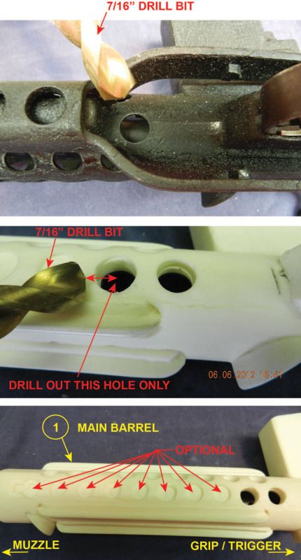
Item #1 MAIN BARREL (lower vent hole)
Flip the main barrel upside down so the trigger and grip side is facing straight up.
The Doopy Doo’s comes with one of the lower vent holes pre-drilled out. (the one closer to the trigger)
In addition to that drilled out hole there are 9 more molded holes that are only depressed a little to give the impression of vent holes.
For my build I am only drilling out the next hole next to the pre-drilled hole.
The other holes are almost totally covered by the folding stock. It’s your option to drill them out or let them as is.
**NOTE** the molded hole all the way at the end near the muzzle with the extra square bit on it is for the folding stock to clip into. On my build I am going to use this hole to mount the folding stock so I do not want to drill it out.
Grab your drill and a 7/16†drill bit and drill out the hole.
-
Going nuts... no.
I am already crazy.

Crazy waiting for my armor to show up.
Back to my padded room.
-
MODIFICATIONS TO RESIN PARTS-
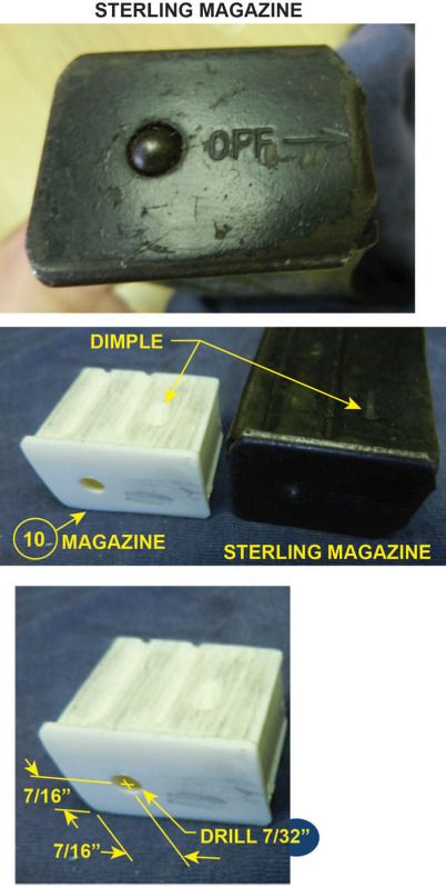
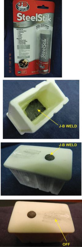
Item #10 MAGAZINE
1. DO NOT fill in the dimple on the magazine like I was going to. I thought this was a flaw in the resin. It is a real feature on the Sterling magazine.
2. Drill a 7/32" hole. It is about 7/16" from both edges. (center to the hole that is)
3. I mixed up a little J-B Weld into a ball and pushed it from the inside of the magazine towards the outside. It made a nice magazine floor plate release button.
4. I tried my best to use my dremel tool to etch in the word "OFF' and the arrow. (not for people with shakey hands)
-
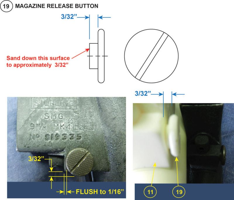
MODIFICATIONS TO RESIN PARTS-
Item #19 MAGAZINE RELEASE BUTTON
The resin button is a bit to tall.
Grab your sand paper and sand down the surface I noted to approximately 3/32". ( a little smaller is good too)
-
THANKS everyone for the feedback
The votes have been tallied and I am going with option #1
Craig
dm101
-
HELP !!!!
I am not 100% sure where to place the Power Cells woth the 3 central Fuses and the bracket (this is from the resin Doopy Doo's build)
I tried to think of 6 variations.
What do you boys and girls think is the correct placement?
Craig
dm101


-
Cool build...I love the custom recticle. You should use it.
So see you to are waiting for your AP armor like me. I ordered mine back on April 17th. How long have you been waiting?
Craig
-
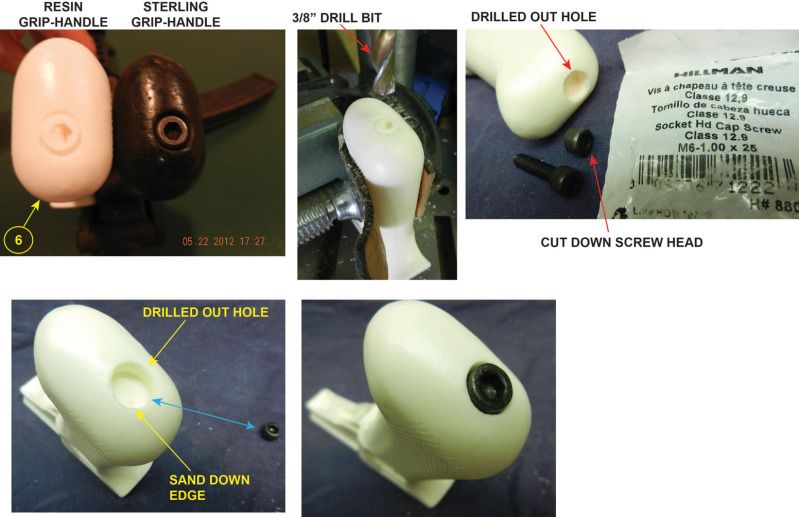
MODIFICATIONS TO RESIN PARTS-
Item #6 GRIP-HANDLE
1- Use a 3/8†drill bit and drill out the molded screw (we call this type of screw a Socket Head Cap Screw)
**NOTE** be careful not to go crazy when drilling the depth. I have a drill press so I was able to set the depth. You want to use the screw you selected to establish your depth. The screw on the Sterling was not recessed. It was almost flush with the top of the dilled hole opening.
2- I decided to use a metric M6 Socket Head Cap Screw. Cut of the head of the screw and pitch out the threaded part (we do not need that). I filed the cut screw head to make sure it was flat (not shown in images).
3- Sand down the edge of the drilled out hole you just made in step #1. There should not be a sharp edge. The edge of your drilled hole should be a nice round radius. I used 120 grit sand paper.
4- I used two part epoxy and set my screw into the hole
-
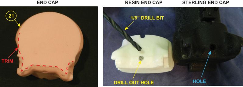
MODIFICATIONS TO RESIN PARTS-
Item #21 END CAP
First thing is to pick up a knife and some 120 grit (or finer) sand paper.
Where I have the RED dashed line (pretty much the whole way around) cut or sand down the excess flashing.
Second that molded dimple is a thru hole. Grap a 1/8" drill bit and drill all the way thru (one side-that is)
-
I was not crazy with the quality of my last image. So i hope this image is better.

-
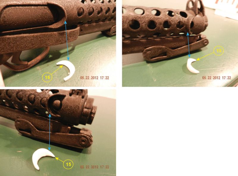
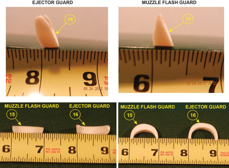
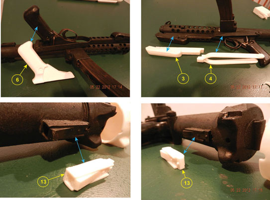
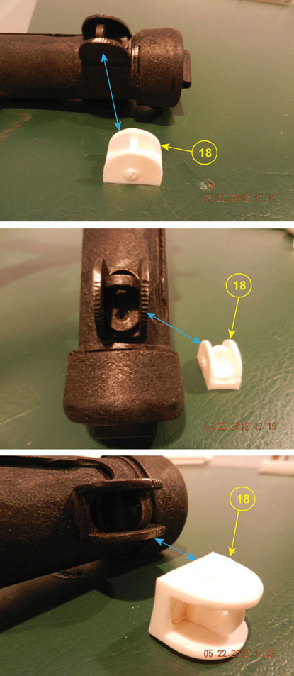
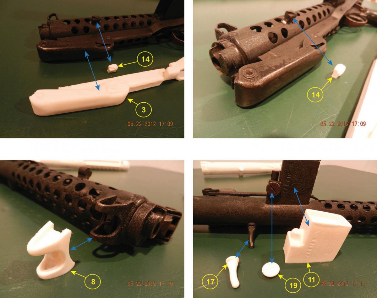
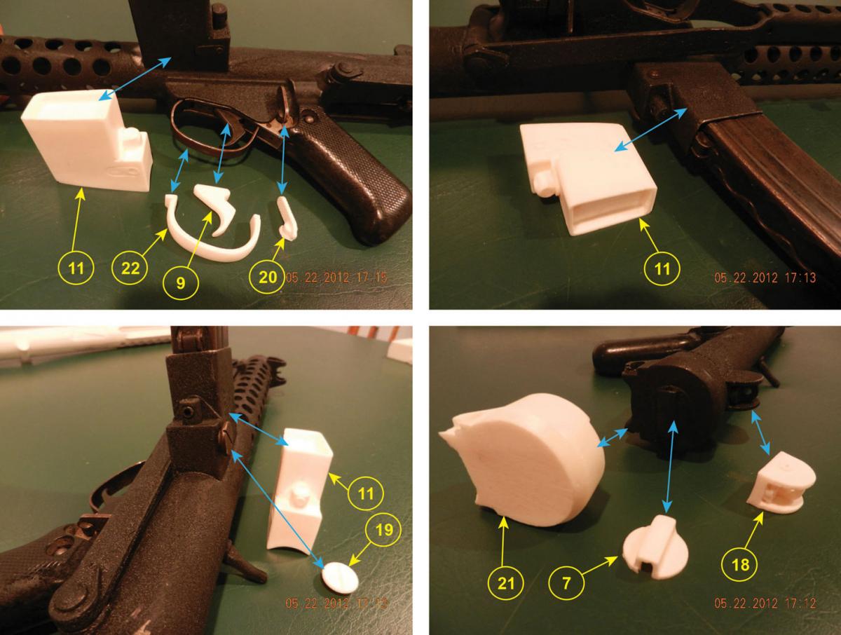
-
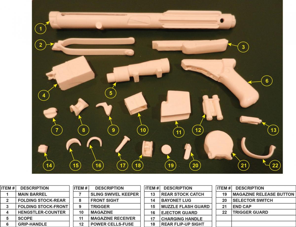
The YELLOW arrows show the part number from my Bill Of Material and the BLUE arrows show the location of the resin part on the real gun.

-
Thanks Jonathan. I must give credit to you. I am using your build tread (and several others) as reference.
I was going to mention this in my opening post- The Doopy Doo’s resin kit is surprisingly detailed and accurate. I know they used a real Sterling to make their molds. Having said that. There is only so much detail you can get with resin. I am very pleased with the kit (except for lack of directions). I would definitely buy another one.
The YELLOW arrows show the part number from my Bill Of Material and the BLUE arrows show the location of the resin part on the real gun.
-
OK here is my attempt to build a Doopy Doos resin E11 Blaster.
This may have been done already but…
The package from the Royal Mail arrived and I eagerly opened it. Balloons and blue arrows
After dumping the bits out on the kitchen table. I triple checked the box for the assembly instructions.
No luck. There were no instructions. No problem how hard could it be, right?
I was lucky and was able to borrow a de-milled Sterling L2A3 to compare resin parts to real steel part.
This is my build thread-
Craig
I laid out all the bits and tried making a Bill Of Material and identifying the parts the best I could. Correct me if my naming convention is wrong. I added the YELLOW balloons to identify the parts on my Bill Of Material.
-
 2
2
-

Belt-Waist and 3-Square Buttons
in Boots, Soft Parts, and other Accessories
Posted · Edited by gmrhodes13
link not working removed
This might be the wrong place for this post.
Who is making and selling a quality Square Button for the waist ammo belt?
-------