LaunchPad
-
Posts
67 -
Joined
-
Last visited
Content Type
Profiles
Forums
Gallery
Articles
Everything posted by LaunchPad
-

1:1 Droideka, yep that what I'm building!
LaunchPad replied to LaunchPad's topic in Non Star Wars Costuming
The paper x-wing my wife made me for our aniversary (paper) gift. New post coming soon. Thx for the coments guys! -
1:1 Droideka, yep that what I'm building!
LaunchPad replied to LaunchPad's topic in Non Star Wars Costuming
Hey all. Sorry so long for an update, between the wife getting deployed in a few weeks, an early vacation before she goes, the kids, a major add on to the house, I’ve not had a whole lot of time. So here are a few of where I stand as of last week. The first thigh is now attached to the hip joint, as well as some of the mechanical gearing for left to right motion for the one. A second thigh is already cut and ready to be welded and I have the steel for the third thigh but not cut out yet. Oohhh Yea, and the first shin and foot are rough cut and starting to take shape!!!! Remember this is only the skeleton for structural support, cosmetics will come after function.. I can’t wait to show you all this thing moving! One of our members in Australia was working the “Where Science meets Imagination” Show there and he had access to the droid in the first pic!!!! He sent me over 90 detailed and up close pics of every part of the droid!!! Soooo, I’ve had to rework a few of the other pieces… so for those of us that anal and look for detail, the pics I post next week, you should notice a big difference in a number of the parts. That’s all for now and thanks for everyone’s comments!!!! Mathew -
1:1 Droideka, yep that what I'm building!
LaunchPad replied to LaunchPad's topic in Non Star Wars Costuming
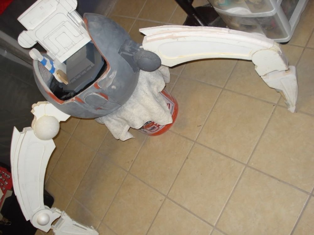
Well, sorry so long for the update for those that are following this thread. I’ve spent every waking hour on these pieces for the spine. Over 120 individual parts and 4 mains for the stem. Not to mention the mistake I made on the thickness and misinterpretation of the side view of the spine. After another trooper (Thanks Brian) submitted me some pics, I had to revamp the spine base and the main shape of the spine itself. If you look close at the spine base pics before, you’ll notice I had to extend the front angle shape by 1.5 inches to allow for the change in thickness of the main spine. So the spine is almost ready for molding. The main leg pins are installed after engineering the exact set up of the rear leg. Notice the hole cut in the rear ring in order to have a pivot point in the same location as the two front legs. The rear one is inset about 0.875” towards the center, thus creating the difference. Also started on the deflector shield pivots and linkage to attach to the spine base. They look like big horse pills. Lol Made of 1.5” PVC pipe and a wet dry vac ball cut in four pieces for the ends. The small “pills” will be made of 0.625” aluminum pipe, with the linkage as 0.1875” flat steel for strength. So here are the pics of where I’m at as of now. The main CPU is back from the manufacturer, I fried two of the chips on the board with the trial and error hook up, but have purchased 2 extra chips just in case. Now I know what not to do, or better yet how I can’t use the board. Haha Will post again soon. Don’t know if I’ll be going past the spine until I’ve completed the legs. Can’t have a droid with no legs just because it’s the most difficult part. More to come. Thanks for the support guys and gals. II'm patiently waiting to post the youtube link to show you this thing walking, but rememer it won't be the same until I have the top complete to offset the weight for balance. I can't wait. Mathew -
1:1 Droideka, yep that what I'm building!
LaunchPad replied to LaunchPad's topic in Non Star Wars Costuming
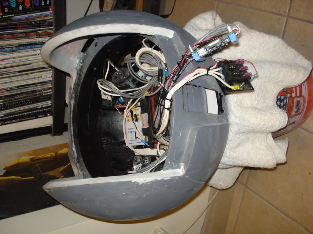
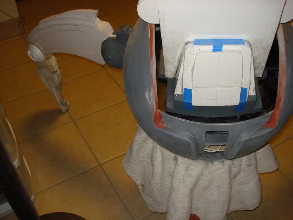
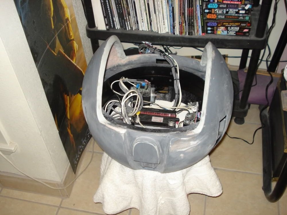
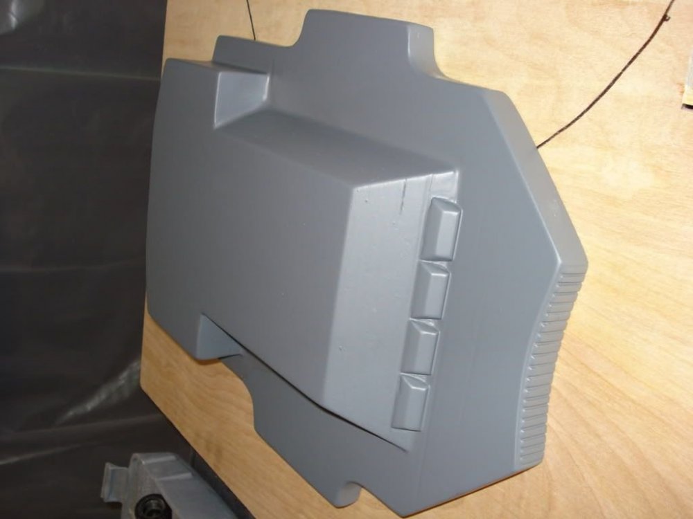
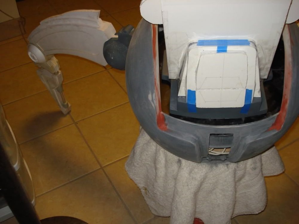
Ok troops, you asked for constant updates to this thread, so here is this weeks progress. I thank all of you for your understanding on what a huge project this is and it adds to my motivation to constantly work on it. I thank my family for putting up with me taking on such a task. Well, I’m having problems with two of the outputs on the controller, so back to the manufacturer for repair. Thank god I’m far enough along as I can do without it for awhile and just work on pieces parts. The controller, motor fuses, power switch, and battery charge plug are going in the back for ease of access for troubleshooting. Shaping for accurate size was first done with foam board, then pressed wood for molds. Very easy to work with. View of access hole through spine base for electronics. These next few are the fitting of the mold for the spine to sit in the base for visual accuracy. Next is the process of actually starting on the details for the spine. I haven’t finished it yet as there are a few hundred individual pieces in order for it to look correct. Should have it completed next weekend. As this was a three day weekend, I had enough time to complete the ball and spine base for molds. . I did some other work on the inside of the ball for the battery and other electronics to mount too, but didn’t take pics of that as I didn’t think that all the guts like the battery holder would be that interesting. If your wondering what’s inside the ball, there are 2 17.5” diameter angle steel rings for the main leg joints to bolt on with support plates welded across for the spine to bolt to through the base. I just haven’t drilled the holes yet. I’m waiting on a completed mold of the spine before designing the skeleton inside it to support the top and electronics to go through. That’s it for now. More to follow as thing this takes more shape. If your wondering why the legs aren’t on yet, they have very complicated guts in the main joints, and they are the most expensive. I have the bearings and some of the gears. Still hunting for a special worm gear and another for the motors. Talk to you all soon. Mathew -
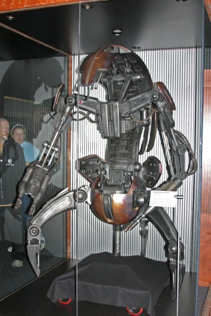
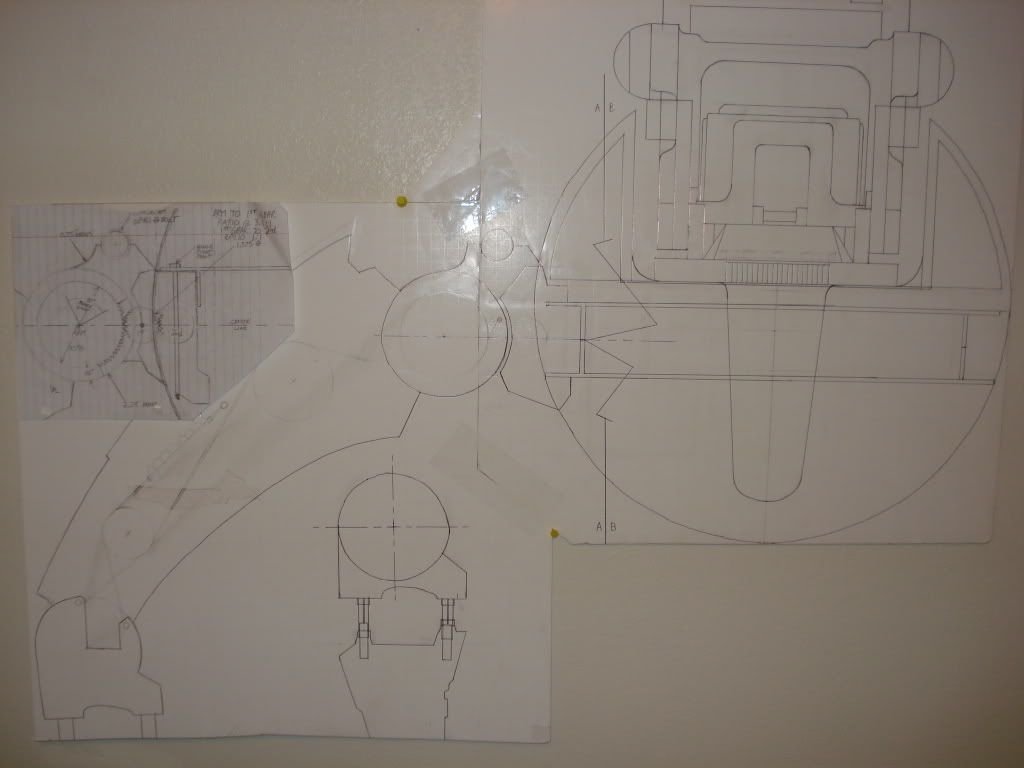
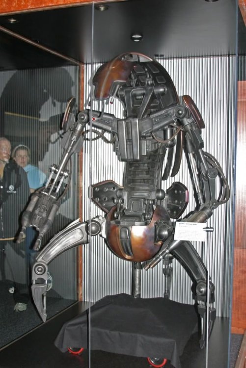
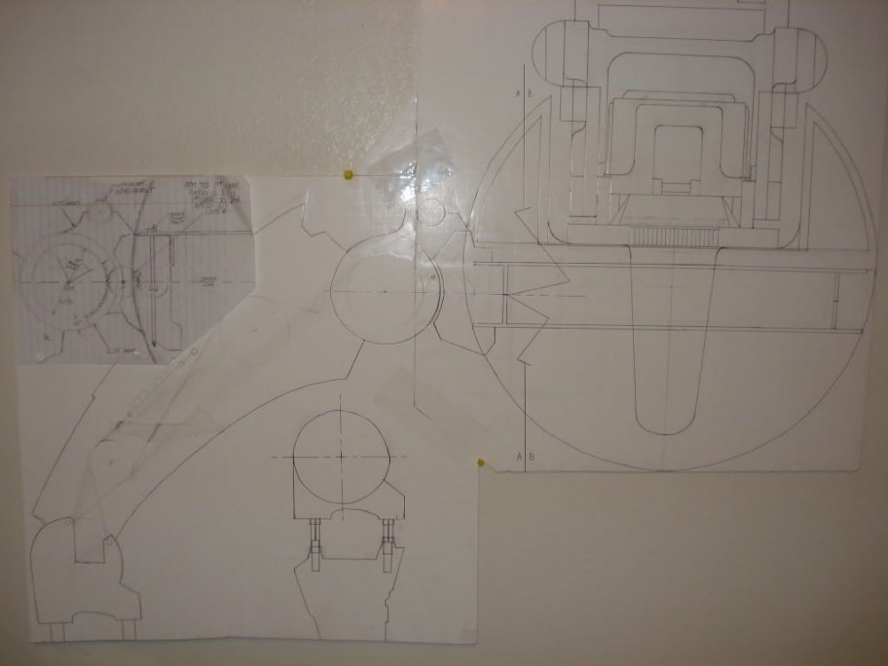
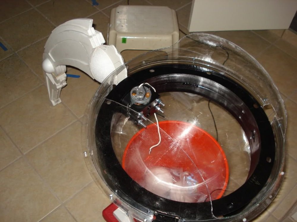
So this is the most detailed pick of one I could find, from what I understand, this is only a model and does not function (Move).I know according to Wookipidia they are exactly 6' tall so my work is the one in this pic scaled at 2.71 from a poster size I had made. The following is the beginning of the drawing process. Afterwards these were drawn in coreldraw and autocad 2006 for machining of the main leg parts. So I finally got my sets of armor complete where I like them and could troop anytime. As a mechanical engineer, when I chose this I knew I would be in a field I would have to learn on my own, electrical engineering yuk, but not too horrible. The following oic started last oct when our movers still had our stuff so I scaled a life size one to past the time. I then proceeded to gather parts in town and on the net to meet the requirements for a self autonomized Droideka. Yes mobile. No rolling up into a ball just yet. Maye once I'm over the mound of trouble with walking Vs Balance with three legs. The main legs are prototyped out of foam, Bondo, and magic sculpt. The main body is layered fiberglass cloth and matting in layer totalling a 0.25 in thickness. The 18" diameter plastic sphere was layered in sections, then areas were removed so the structure would still be stable' MModing and scaling the lower soins guts are proving to be very difficult but not impossible. This was where I stopped last week. Since then I have started putting together the gears for shoulder movement in the legs which does consist of all directions. Everyone was making R2, so I wanted to build a functional droideka, not RC, but with a TechFX micro controller and Pololu motor controllers. Further update as this starts to come together more. Let me know what you think. I haven't posted in awhile as right after the move I began this secret project. Muhahahah. lol Mathew

-
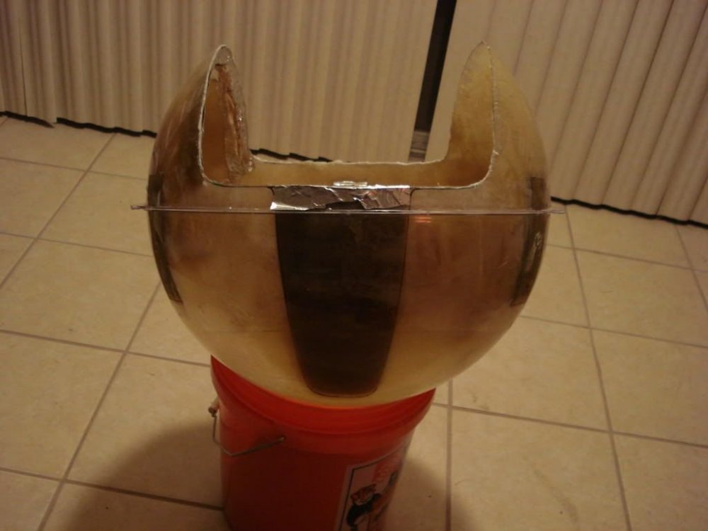
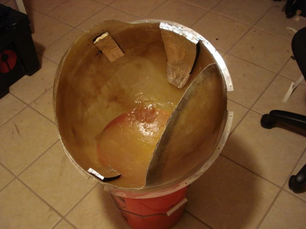
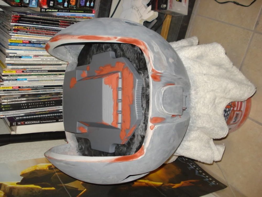
Almost all glassed in now. Most of these pics are from last week.Since then I have made the lower juts more rounded and installed carriage boblts for the visor hinge. I will admit this was a starfortress bucket used for the base, although now looks 10 times more accurate than his. Suppose I could have just used a foam head to work from. As soon as I near completion I will post more pics of the final mold and the first casts. I love this %^$#. It gives me something to be proud of. Long live the 501st!!!! I may also offer these if there is enough interest. Well, what do you think? This all glass, magic sculpt, and clay made by hand. Not done yet, but almost. Soon, very soon :wink: