
FISD E-11 Reference Team
-
Posts
53 -
Joined
-
Last visited
Content Type
Profiles
Forums
Gallery
Articles
Everything posted by FISD E-11 Reference Team
-
FISD E-11 BLASTER REFERENCE
FISD E-11 Reference Team replied to FISD E-11 Reference Team's topic in ANH BlasTech E11
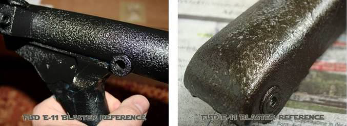
#28 - Painting It is highly recommended to wear some form of respiratory protection when working with spray paint. All surfaces that will later be glued can be covered with masking tape, so you save yourself from laborious paint removing for better adhesion. In case your kit parts got heavily sanded or dusted during the build, it might be an option to wash all parts again like shown in chapter #03. Before adding any paint to a part, make sure these have fully dried and use a primer first. When applying primer and paint, try to keep the layers thin, as several coats of thick paint will reduce the details on the surface. This is especially important for paint jobs with multiple layers and structured paint. Avoid any paint tears on your build - these were only on the TK helmets. Decide how you want your blaster to look like. Flat black finish with no weathering like seen at the Death Star? Heavily weathered Tunisian Bapty from Tatooine? Crinkle paint as the real Sterlings had? You see, there are various ways to build a screen accurate blaster. The same can be said for the paintjob itself. Mod A: Simply use flat black spray color on all parts for a factory-new look. Gloss black is not recommended for the gun's main body. Mod B: The grip from the original Sterlings was some kind of black plastic, which can be recreated with semi gloss or gloss black paint. Mod C: Parts in the trigger group and the inner bolts were made from metal. Check reference pictures and use some metallic-grey or steel-like colors for these. Mod D: Using two slightly different kinds of black on separate parts can make your build appear much more realistically. Attention: Separate your build parts in two groups: 1) components representing the Sterling. 2) additions by the prop makers for turning it into an E-11 blaster (scope, scope rail, counter box, power cylinders and T-tracks). Do not use different types of black within the gun's body. Mod E: In case a dry-brush weathering (see chapter #29) is not sufficient for your build, you can integrate a layer of metallic-grey or steel-like color after priming and before applying the black paint. When later weathering edges and corners with sandpaper, this will result in having nice metal effects shining through the black color, looking like heavy usage. Alternatively you can mask off some places before adding the black paint. Masked spots will later look like paintchips. Attention: This is only to be used for parts of the main gun and the power cylinders - not for other additions like scope, scope rail, counter box and T-tracks. Full resin builders will have to cover the T-tracks with tape, as these are one part with the receiver tube and can not be separated. Mod F: To recreate the structured surface of some real Sterlings, you can integrate another paint layer - crinkle paint or hammered finish paint. Attention: This is only to be used for parts of the main gun, except the grip, the trigger section and the magazine. Do also not use this for the additions by the prop makers (scope, scope rail, counter box, power cylinders and T-tracks). Order of layers: primer, metallic grey, structured paint, flat black. The metallic grey is not mandatory if you plan to add dry-brush weathering instead of sandpaper weathering. For the crinkle paint, please exactly follow the instructions on the spray can. The hammered finish paint can be paper dabbed with a kitchen roll paper while drying to add more structure to its surface. Depending on how that layer looks, you could possibly skip the last black coating. Mod G: The scope should be painted in brass. Before adding the black layer, mask the feets (both feet on bottom and rear foot on the sides too) and run a thin wire through that gap at the front. When the black paint fully dried, you can unmask everything and weather the scope with fine sandpaper. Alternatively you can skip the brass coat, add the black paint and some brass colored dry-brushing. Mod H: The counter should be painted in flat black. Make sure to cover the counter window from the outside and the inside. Do the same for the number rolls, as you don't want any paint fog on these. When using a real counter, cover the coil if you later still want to have that label visible.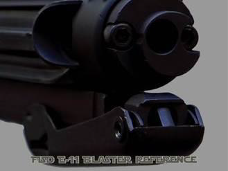

-
FISD E-11 BLASTER REFERENCE
FISD E-11 Reference Team replied to FISD E-11 Reference Team's topic in ANH BlasTech E11
#27 - Assembling As there are various resin kits available, each of them unique in their own way, there is no chance to create a universal step-by-step guide. However, you should begin with selecting your favourite modifications, depending on your kit, skill level and personal preferences. To avoid any conflicts within selected mods, re-check if some of these might affect others. Start doing the individual mods for each part and try not to glue anything at this early stage. Think of accessibility to each part (also the small ones) for painting. Glue only when you can be absolutely sure, you will not have to disassemble that specific section later. Surfaces to glue should be roughly sanded before applying the glue. For resin to resin connections CA glue works best, while resin to aluminium requires universal liquid glue. Whatever you choose, make sure it is instructed for use with the materials in your build. -
FISD E-11 BLASTER REFERENCE
FISD E-11 Reference Team replied to FISD E-11 Reference Team's topic in ANH BlasTech E11
#26 - The Power Cylinders Andy (PlayfulWolfCub) has done an incredible research on this part and we highly recommend his PDF document, which can be found here. Mod A: You can run a scratch build or modify the resin version from your blaster kit (if available). A useful update had already been created by Tino (T-Jay). The links can be found here and here. Mod B: Another thing you can do is to completely replace the power cylinders with a more accurate version, available on the FISD. Mod C: And you can scratch build these from metal. A useful thread had already been created by Aaron (usaeatt2). The link can be found here. Placement of power cylinders can be parallel to the receiver or parallel to the end of the magazine well. Both is screen accurate. Make sure to place the power cylinders towards the outer edge of the magazine well, to avoid any problems with the holster. There is also evidence of some power cylinders being additionally supported by a wire, simply wrapped around the mag well (see ANH when Luke lifts his blaster for reference).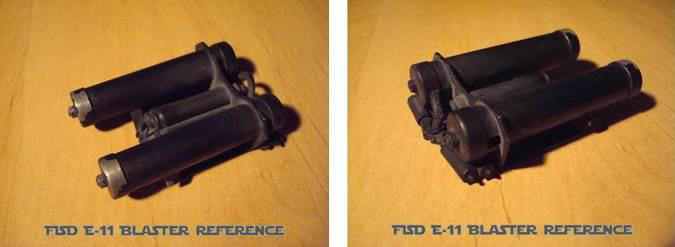
-
FISD E-11 BLASTER REFERENCE
FISD E-11 Reference Team replied to FISD E-11 Reference Team's topic in ANH BlasTech E11
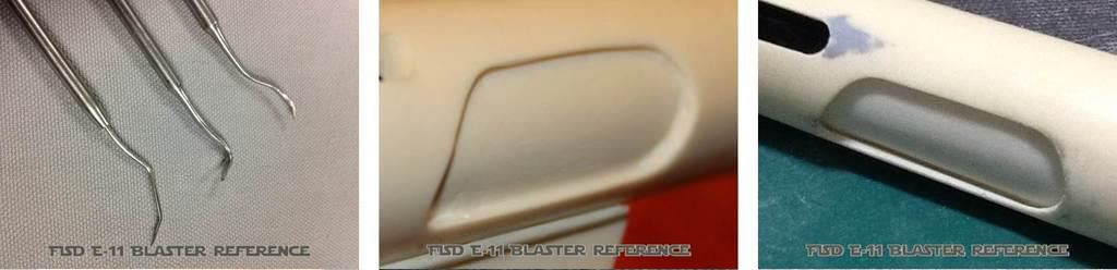
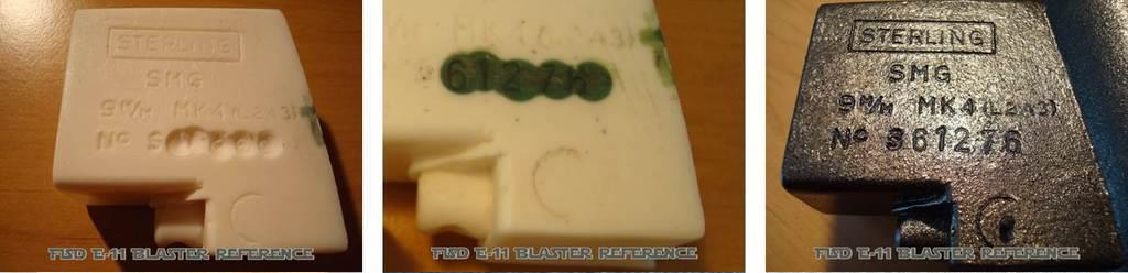
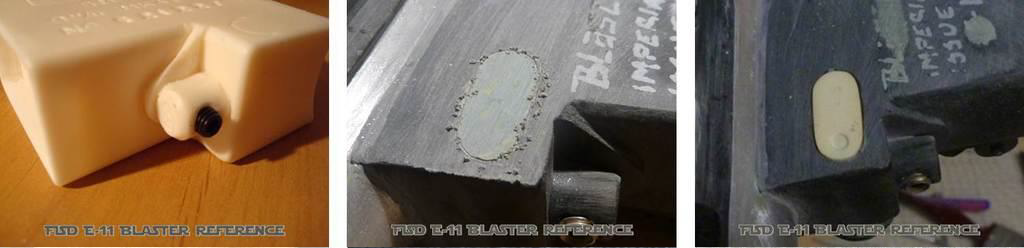
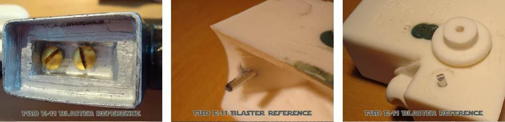
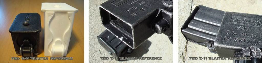
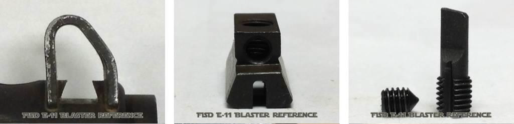
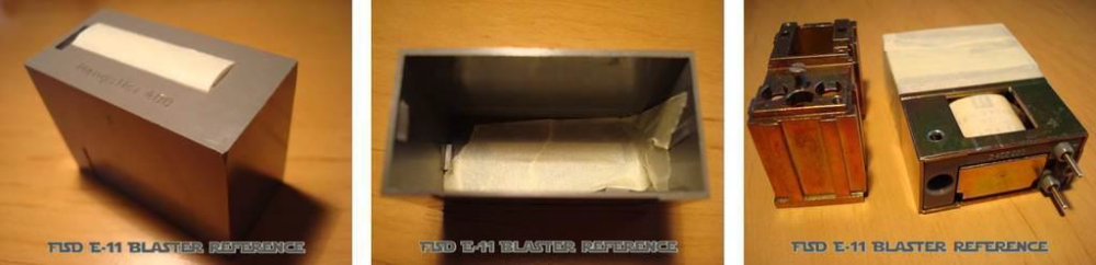
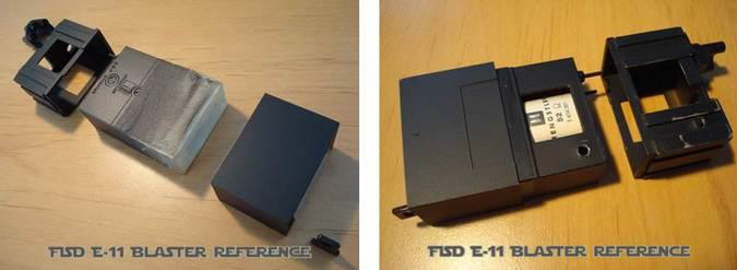
#25 - The Hengstler Counter Mod A: Sand down the front half of the resin counter to have a flat "face". Use the measurement diagram to create a recess for the new number window at the correct position. Get the "printed numbers" and make sure they fit into the new opening. Cut a piece of Plexiglas to fit into that and sand or file the window front to get the D-shape. Then patiently sand and polish it to get a clear view through it. Use sandpaper grits like 180, 220, 320, 400, 600 and 1000. The polishing wheel from your rotary tool (at the lowest speed) will help for the final glossy surface finish. Do not glue the printed numbers to the Plexiglas or into the recess. Only use very little glue to install the new window. Mod B: The original counters were available with and without a manual reset button. To recreate a reset button, take a piece of plastic (3mm thick) and work it to have the correct shape. It can be glued to the counter but will very likely break off. To avoid this, it can be made longer to rest deeper in a slot. For a moveable reset button you need a sheet of plastic, sized to match the "face" of your resin counter (25 x 50 mm). Create cutouts for the number window and the reset button by using the measurement diagram to have these at the correct places. Sand down the "face" of the resin counter according to the thickness of your plastic sheet. Transfer the opening for the button onto the resin body behind the sheet with a pencil. Make a recess for the hidden part of the button into the resin body and drill a hole in the center for a small spring from a ballpoint pen. Cut the spring to the required length and test fit everything before adding glue. When the new "face" has been installed, the remaining gap to the resin body can get closed with modeling clay or bondo cream. If your resin counter lacks the details on the bottom, these can be recreated with pieces from a 1mm ABS sheet. To get the correct dimensions, just see the top of your counter's bracket, as the original sockets were designed to be slot-fitted into each other. So, bottom and top are inverted. Mod C: If available, real parts can be added to the resin counter for a more realistic view. For example the little screw on top of the cover, the brass screw next to the Hengstler logo, the electrical connector block or even the soldering pins. Mod D: The "Conversion Counter" actually is the front half of a counter, very identical to the Hengstler 400 Series. It requires a resin counter, which is included in most available kits. Cut off the rear half of the resin counter and mount or glue it to the front half from the conversion kit. To get additional stabilization, the counter arm from the scope rail can be modified to support both, the front and the rear half of the conversion counter. Mod E: All previous steps can be ignored when buying a real Hengstler 400 counter. But be aware of the many different versions you might find: - 4 to 8 number rolls - sometimes the last 2 numbers are in a different color (yellow or red) - sometimes the last 2 or 3 rolls are in a different color (white) - with or without mechanical reset button - old Eagle-logo or the H-logo - gold-coloured metal socket or black plastic socket - with or without the 2 soldering pins - window in D-shape or flat - with or without small screws in the front cover - with or without "Hengstler 400" thermal stamp on the counter face You can examine some counter variations in chapter #33 - Gallery However, the screen accurate counter should have 6 numbers (all white lettering on black background), a reset button and ideally it will have the old Hengstler logo, showing the numbers 8, 9 and 0 flanked by two wings - the "Eagle Counter". A very useful "HOWTO" had already been created by Aaron (usaeatt2). The link can be found here. Mod F: Coiled wires between the counter and the cylinders were not used on screen, only on promotional pictures. There is also evidence of some counters being additionally supported by a wire, simply wrapped around the scope's feet (see ANH Leia's escort scene for reference). -
FISD E-11 BLASTER REFERENCE
FISD E-11 Reference Team replied to FISD E-11 Reference Team's topic in ANH BlasTech E11
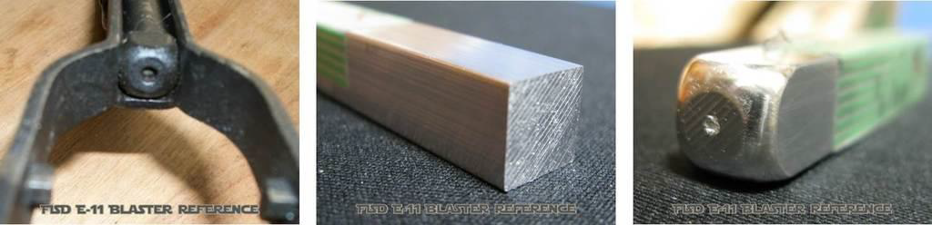
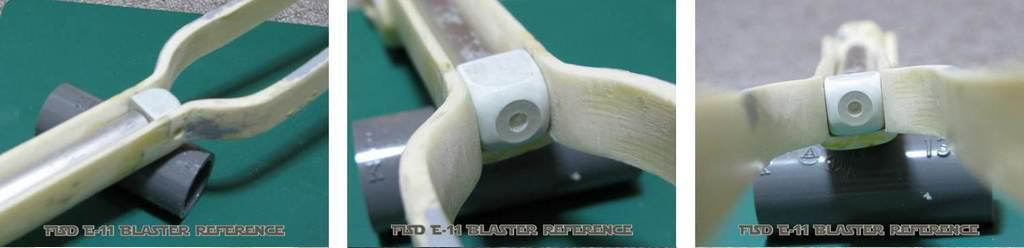
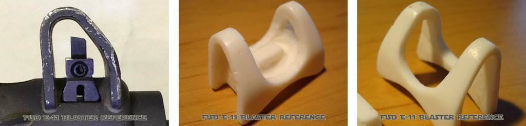
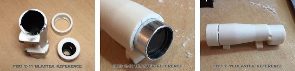
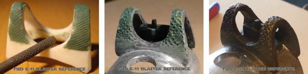
#24 - The Scope Rail This part should be made from metal (steel or aluminum, thickness 1.5 ~ 2mm) and will later be used to mount the scope and the Hengstler counter. Aluminum is easier to shape and strong enough to support the weight of real components. If using a vice for bending, make sure this does not damage the surface of your metal strip. Accessory placement: The rear foot of the scope should be aligned with the folding stock pivot. The top of the counter should be aligned with the centerline of the scope. The Hengstler logo should be aligned with the front foot of the scope. Screen accurate vs. idealized: The screen used rails were not 100% parallel to the receiver tube. On the front end, these rested closer to the receiver (not perfectly horizontal to the receiver the entire length). Also the bend itself was not exactly a "sharp" 90 degrees bend, but more rounded. See some movie stills (picture 1) and build threads (picture 2) to help you to decide how you want yours to look like. The rail can be made from one part (counter bracket included) or two parts (counter bracket made separately). For the one-pieced version, you will need a metal sheet big enough to cut the complete shape, including the arm/bracket to hold the counter box. The two-pieced version is a bit easier. Make the long rail first and then make a separate little part for the counter box. The bracket will then be mounted to the underside of the long rail. This somewhat reduces the space between the receiver tube and the rail which will require smaller screw heads to be used for mounting everything. This is also to prevent the screw heads from possibly scratching the receiver. Attention: Check references regarding the position of scope and counter before drilling any holes into the rail! When you are sure about the placement, transfer the holes from your scope's feet onto the rail (and if applicable to the counter arm). Pay close attention to every step while doing this! Also there is no right or wrong way about what end to start with first. Study available graphics before bending the metal stripe. A little cut on the underside (crosswise) will make it easier and guide the metal to bend evenly and correctly. Then shape the front end to fit into the first venting hole on top of the receiver tube. Leave a little "tongue" which you can bend towards the front muzzle. This will protect your rail from falling out. The visible area between the receiver tube and the rail's front bend can be shaped to smoothly fit the receiver's contour. For the rail's rear end there are four options to choose from. It can be shaped to simply fit straight into the rear sight, screwed directly down into the sight base. It can have an additional 90 degrees upwards bend, mounted through the rear sight with a nut and a bolt (no screen references found yet). A shorter rail can also be mounted to the receiver tube with a "Z-bend" just before the rear sight. And the "V-bend" is ideal in case of a missing (or removed) range aperture. A hex nut and bolt then keep the rail in place. There is also evidence of some counters being additionally supported by a wire, simply wrapped around the scope's feet (see ANH Leia's escort scene for reference). -
FISD E-11 BLASTER REFERENCE
FISD E-11 Reference Team replied to FISD E-11 Reference Team's topic in ANH BlasTech E11
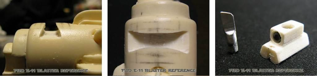
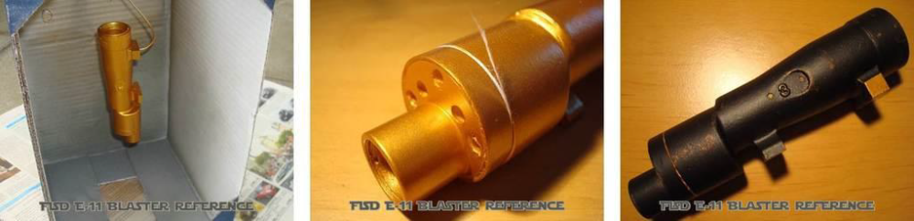
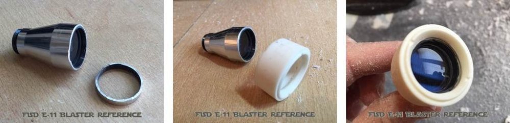
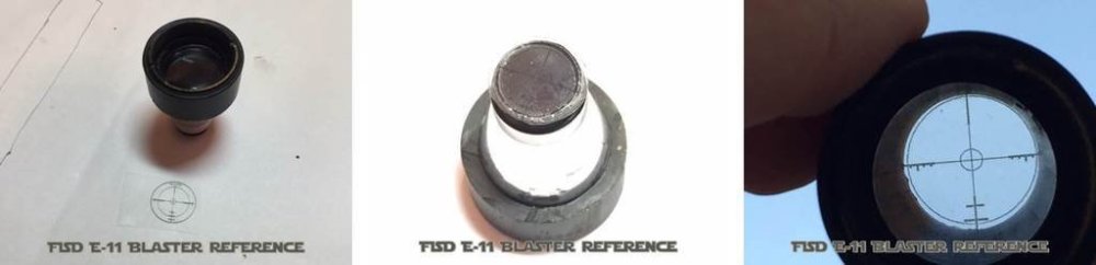
#23 - The Scope Mod A: Drill holes in the center of your resin scope's feet, to later mount it onto the scope rail. The hole in the rear foot will not be in the center! You can add one of the available E-11 scope target decals to the rear end and a circular cutout from a CD (compact disc) to the front end. Mod B: Alternatively you can drill straight into both scope ends with appropriate bits (for example spade bits) to install some lenses, made from glass or plastic. On the rear end of the scope, taper down the inner hole by using smaller/thinner bits when drilling deeper to later get a realistic internal view. 10mm is the visible diameter for the front lens, 22mm for the rear lens. Remember to paint the inside of the scope before gluing these in place. If carefully done, you can make both drill holes meet each other (creating an opening from one end to the other), enabling light to shine through the entire scope for added realism. Mod C: Additionally you can replace the 5 resin screws on the scope's front with real metal screws. At first you have to remove the resin screws (with your rotary tool) then drill small holes for the new screws and add these. Mod D: If Mod B is not sufficient, parts from a small monocular can be installed into a hollowed resin scope. Both ends have to be cut off and trimmed to receive the upgrade parts. The scope's main body needs to be hollowed all the way through and should be painted black on the inside before closing all joints. For even more realism, any matching kind of reticle lens can be added to this construction.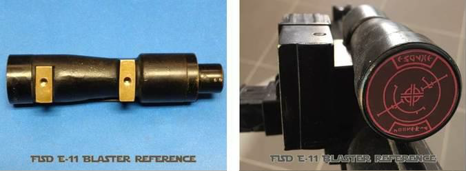


-
FISD E-11 BLASTER REFERENCE
FISD E-11 Reference Team replied to FISD E-11 Reference Team's topic in ANH BlasTech E11
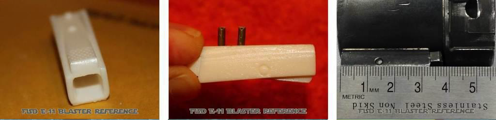
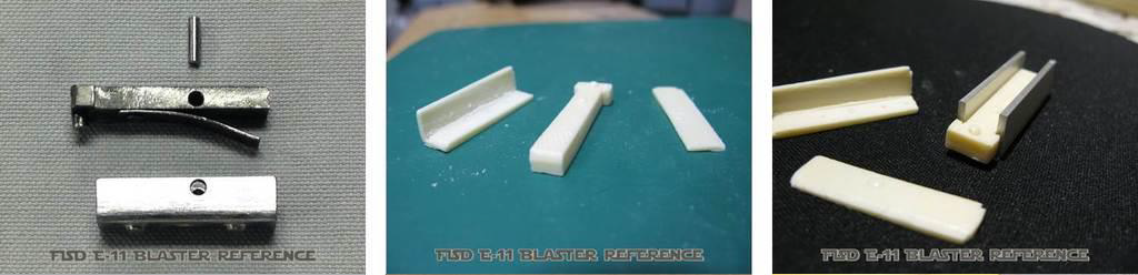
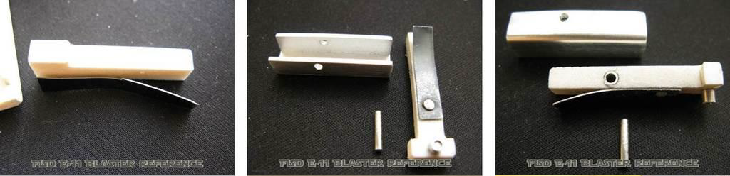
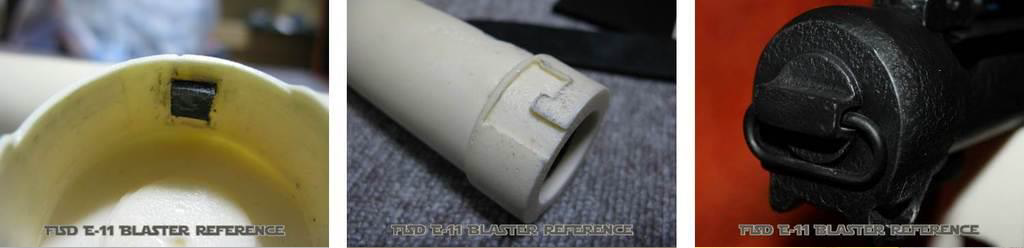
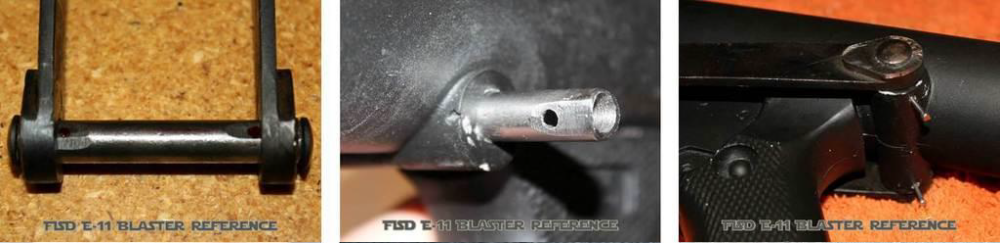
#22 - The End Cap Clip Mod A: Hollow the open side of the clip to make it more realistic. For trooping purpose, the end cap clip can be reinforced with 1 or 2 metal pins. Check reference pictures for final placement on the receiver and leave a little gap between the end cap. Mod B: A moveable end cap clip can be made with an aluminum U-channel. Cut the T-piece out of the resin version and fit this into the aluminum channel. Drill a hole at the correct position (see below) for the pivot pin. Measure and cut a metal pin. Make it sit flush with both sides of the channel.

-
FISD E-11 BLASTER REFERENCE
FISD E-11 Reference Team replied to FISD E-11 Reference Team's topic in ANH BlasTech E11
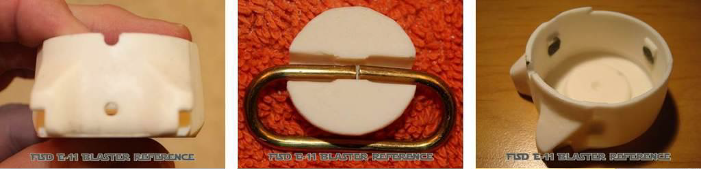
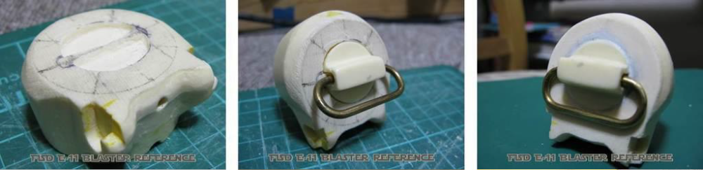
#21 - The End Cap With Lock And Ring Mod A: Drill that small bottom hole. Get an accurate metal ring (often called D-ring although it actually is 0-shaped). Modify the ring holder to fit over the ring. Fit it tight to avoid any rattling noise, or wrap some layers of insulation tape around the metal. Reinforce or replace the three locking notches to create more stabilization (otherwise the spring might blow off the end cap). Make sure the end cap lock is properly working and keep in mind that additional paint layers might later make this more complicated. Mod B: Carve a shallow recess into the end cap, the same size area as the ring retainer base. Once the desired depth to sink the retainer into the end cap is set, glue it into place and fill any seams with epoxy. Sand to a smooth finish.

-
FISD E-11 BLASTER REFERENCE
FISD E-11 Reference Team replied to FISD E-11 Reference Team's topic in ANH BlasTech E11
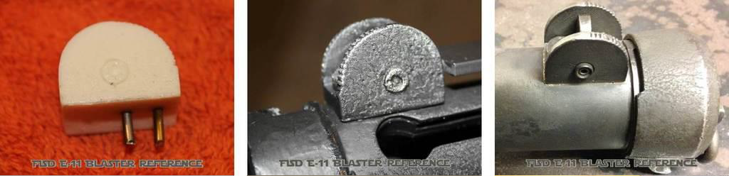
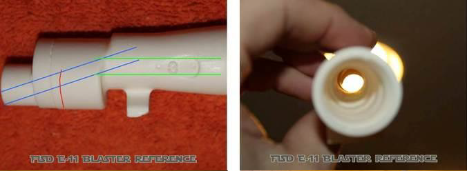
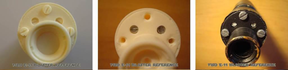
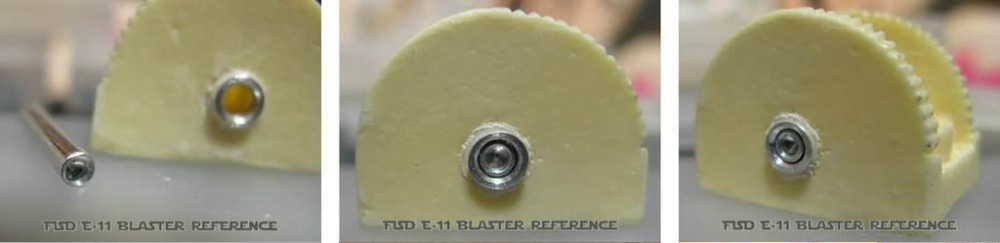
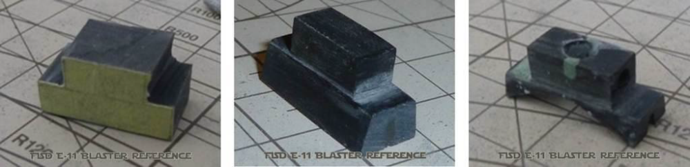
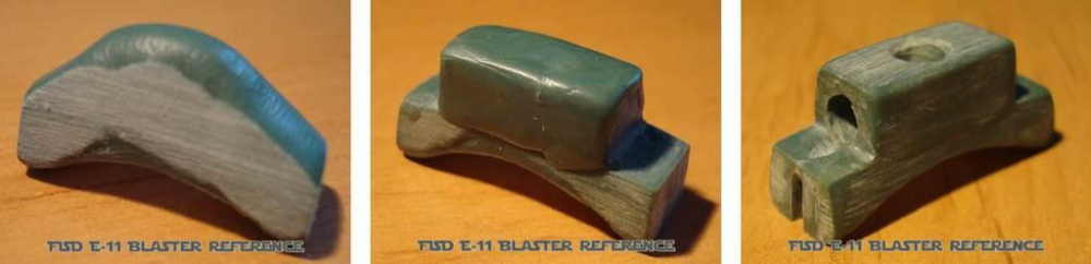
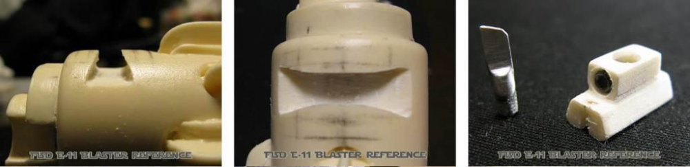
#20 - The Rear Sight For trooping purpose, the rear sight can be reinforced with 1 or 2 metal pins (a good idea if your scope rail will be mounted to this). When adding it to the receiver tube, leave a little gap (about 2mm) to the raised end of the receiver tube (locking notch band). Check to ensure there is enough clearance for the end cap to move. The serrations must face to the rear of the blaster, not towards the scope (an often made mistake). Mod A: Drill a hole through the rear sight the same size as the inner hole. Cut a solid aluminium shaft slighlty longer than the length of the drill hole. With a dremel and metal drill bit (a size slightly smaller than that of the shaft), drill a shallow hole on each end of the shaft until it appears like a cup. Finely sand to remove sharp edges and polish to a finish. The outer ring can be fabricated with aluminium tubing or eyelet rivets. A larger opening on each end will need to be made to fit this but do not make the depth of this hole any deeper than the rear sight wall itself.
-
FISD E-11 BLASTER REFERENCE
FISD E-11 Reference Team replied to FISD E-11 Reference Team's topic in ANH BlasTech E11
#19 - The Recoil Spring If you want to make a functional bolt, you will need a real spring going from the inner bolt to the end cap. Standard wires will only have minimal recoil effect, which is fine for static builds. Get a 1.8mm wire and find a pole or long cylindrical object with an adequate diameter to wrap this wire around (for example the thing from which you made the extended rear end of your inner bolt - in case this mod has been selected). Stretch the finished spring to have the same number of coils visible through the charging handle slot (when end cap is attached) like real Sterlings have. -
FISD E-11 BLASTER REFERENCE
FISD E-11 Reference Team replied to FISD E-11 Reference Team's topic in ANH BlasTech E11
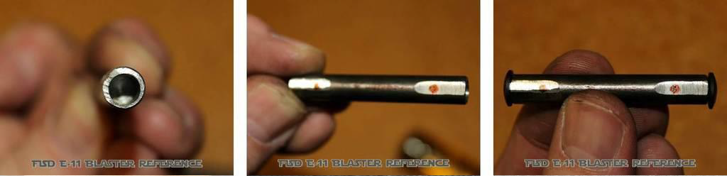
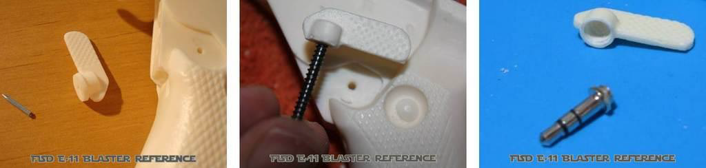
#18 - The Charging Handle And Rear End Of Inner Bolt The charging handle is always at high risk of breaking off, so stablilization is mandatory - especially for operational bolts. An installed screw works fine and after cutting the head off, it can be used to connect to the inner bolt. Be aware you can only reach some places while bolt and handle are not installed. Once these parts are installed, accessing some areas inside the receiver becomes limited or even impossible. Shape the charging handle to fit and slide through the long charging handle slot and leave a little gap at the very end as seen in the photo below. Study reference pictures about the rear end of the inner bolt and recreate this from scratch. Be aware the spring should later slip over this and still have enough room inside of the receiver tube.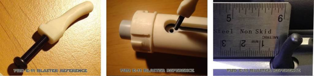
-
FISD E-11 BLASTER REFERENCE
FISD E-11 Reference Team replied to FISD E-11 Reference Team's topic in ANH BlasTech E11
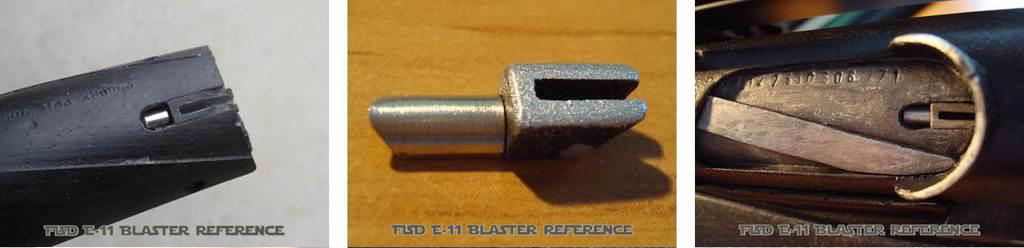
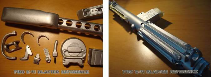
#17 - Inner Bolt With Clearing Strip, Serial Number, Plunger And Extractor Mod A: Check reference pictures to see if the position of the clearing strip in your kit needs to be corrected. If so, you can sand down the wrong strip and replace it with a 1mm strip of plastic. Use a heat gun to twist it and reduce (or fill) any gaps between the strip and the inner bolt. Mod B: To create or change serial numbers on the inner bolt, the same technique can be used as mentioned in Chapter #15 Mod B regarding the magazine well. The numbers have a height of 2mm and a total amount of 15 characters (a combination of 13 digits & 2 letters). The setup is as follows: X00 0 000 000 X 0000 (the X stands for a letters and the 0 represents the digits). Hollow some space and fill it with modeling clay. Make new imprints while the clay is soft. Alternatively you can engrave them. Mod C: To simulate the extractor and plunger, carve these into the inner bolt or find and make some parts to insert there. Attention: Only a few early Sterlings had the "slotted" extractor as shown here. The majority had the solid extractor (without that slot). See also chapter #30, Blueprints: Bolt Detail and Bolt Parts. Mod D: The bolt can also be recreated using scratch parts and a thin aluminum sheet.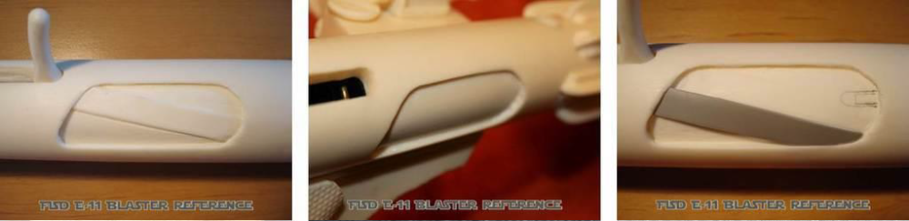


-
FISD E-11 BLASTER REFERENCE
FISD E-11 Reference Team replied to FISD E-11 Reference Team's topic in ANH BlasTech E11
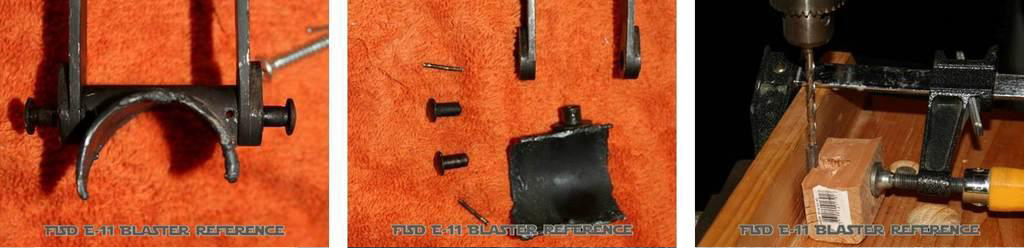
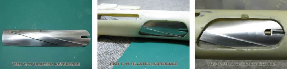
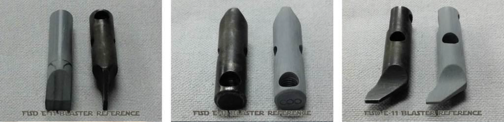
#16 - The Ejection Port And Ejection Port Guard There should be two C-shaped guards in your kit. In case these are not the same size, use the bigger one for the ejection port. Please re-check chapter #10 and use these tips and tricks on the ejection port guard. Mod A: If your inner bolt is molded as part of the receiver tube (full resin builds), you can carve the outer area with a fine tool, making it look more like two separate parts.
-
FISD E-11 BLASTER REFERENCE
FISD E-11 Reference Team replied to FISD E-11 Reference Team's topic in ANH BlasTech E11
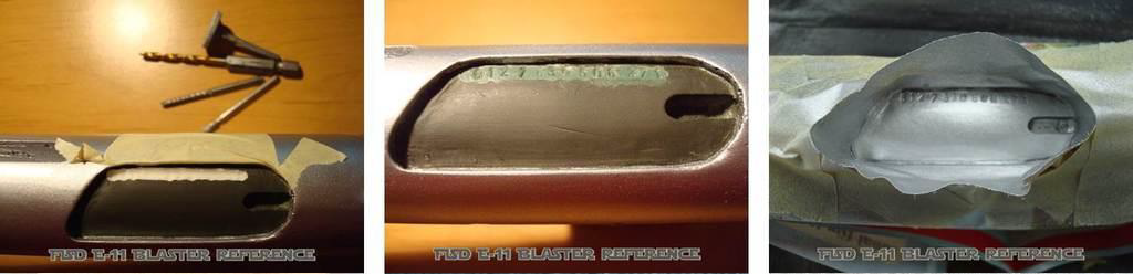
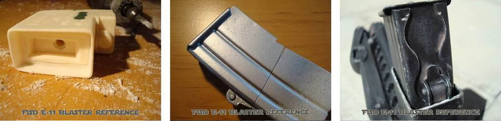
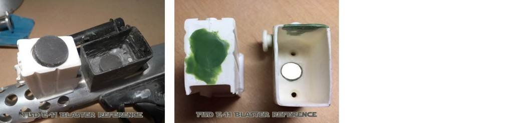
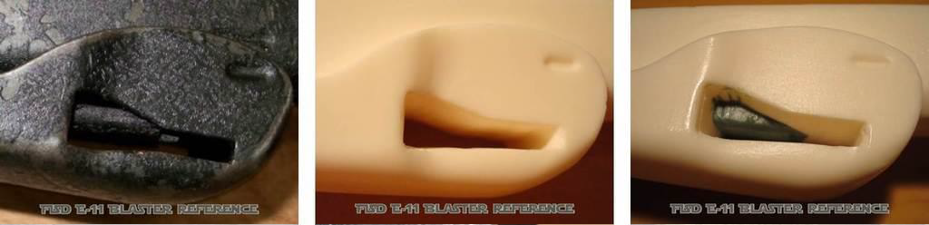
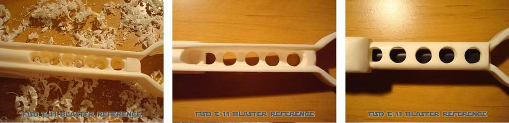
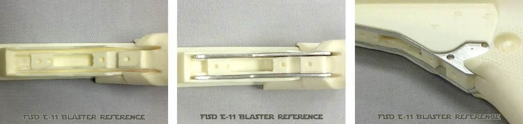
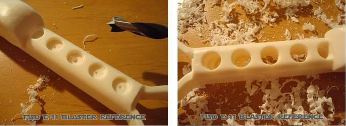
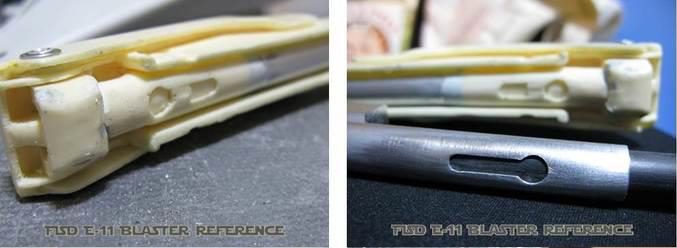
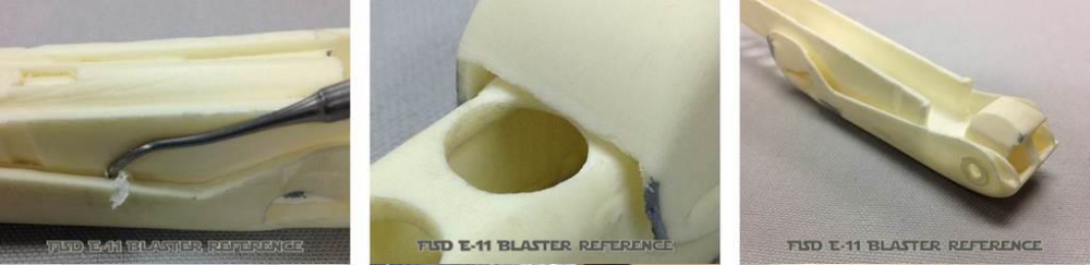
#15 - The Magazine Well Mod A: In case you replace the magazine with a more accurate one, it might not fit into the magazine well without thinning its inner resin walls. Use a rotary tool for this and be very careful to not break the thin walls! Choose if you want to leave the magazine in full length and completely hollow out the magazine well, or instead cut the bottom end of the magazine (which won't be seen later) to fit in the opening. Mod B: On top of your magazine well there might be some imprints and serial numbers, which are the same on all kits from that mold. You can change these for example to your individual 501st-ID. Just remove the current letters or numbers (with a rotary tool or electric screwdriver with drill or sand bit), fill the holes with modelling clay and use 4mm punch numbers to create new imprints before the clay cures. Alternatively you can engrave them. Bear in mind: adding power cylinders will cover most of this work later. Mod C: For a higher level of details, add some separate parts. Easiest is the set screw, which can be drilled and replaced with a real one (grub screw). On the underside of the magazine well is an oval inlay. Recreate this from a separate piece of metal, plastic or modeling clay and replace it for more realism. Mod D: When attaching the magazine well to the receiver, it is optimal to add some stabilization - especially for trooping purposes or if the magazine is heavy (massive resin block or filled with batteries). Depending on the inside of your magazine well, you can run 1 or 2 screws through the back into the receiver tube. If that space is required for something else, small metal pins will help (install like wooden dowels). The same should be done to support the round magazine catch screw located on top of the magazine well. As the original magazine housing is welded onto the receiver, any remaining gaps can be closed with a thin line of modelling clay, epoxy or cream. You can make this even look like real weld beads. Mod E: The ejector in the mag well (long black part in first photo) can be fully recreated from scratch for even more realism. Mod F: To build an operational magazine release button, install a spring-powered rod from top to bottom and recreate the inlay from the underside. Then attach your inlay and the resin button to that rod. By pushing the button now, the inlay will move a little bit out of the magazine well. Mod G: To achieve a realistic magazine well, fill the rear side with modeling clay, remove the resin ejector and drill through it. A solid rod (aluminum or plastic, OD=8mm) can be shaped to match the real ejector. A diagonal cut on the end gives the required leftover, to recreate the „jet tail“ (add this later to avoid breaking it off). A hole of about 5mm should go through both, the ejector and the magazine well. Then drill a hole for the grub screw and cut threading on the inside. Do not forget to shape the ejector top end at 45 degrees.


-
FISD E-11 BLASTER REFERENCE
FISD E-11 Reference Team replied to FISD E-11 Reference Team's topic in ANH BlasTech E11
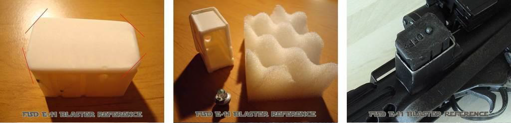
#14 - The Magazine Mod A: If your magazine is not accurate enough you can sand the edges of the top plate to be more rounded/soft and file the angles of the 4 outer corners (be aware of different angles at front and rear). Drill a hole and add a little 5mm knob (for example with a LED) and fill the magazine body (for example with foam). Also you can engrave the letters "OFF" and the arrow into the top plate (make sure your letters are upside down when the magazine is inserted and the arrow is pointing forward). Mod B: Another thing you can do is to completely replace the magazine with a more accurate version. In that case, you might have to deepen the opening of the magazine well to have the magazine insert at the correct depth. You may also have to thin down the inner walls on your magazine well to insert the higher quality resin casted magazines. Thinner walls make it more fragile so be careful not to break the resin here. Mod C: For a removable magazine, magnets can be installed and these can be hidden under a thin layer of modelling clay.


-
FISD E-11 BLASTER REFERENCE
FISD E-11 Reference Team replied to FISD E-11 Reference Team's topic in ANH BlasTech E11
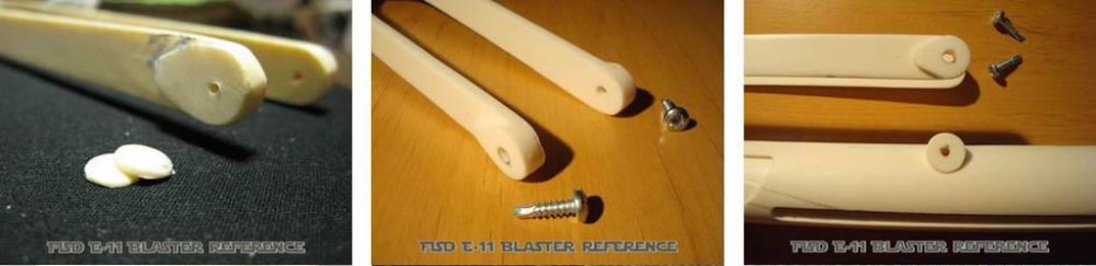
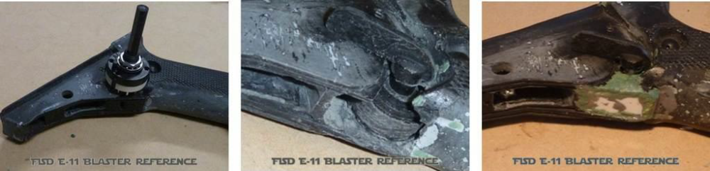
#13 - The Folding Stock In case your kit comes with a folding stock made from 2 pieces, these must be joined together. Connecting the two parts with some support rods will add durability and ensure the parts remain in place while the glue/epoxy sets. The remaining gap will need to be filled and sanded to a smooth seamless finish before painting. Mod A: A commonly made mistake is to completely hollow the opening shown below. On real Sterlings you can still see a latch inside. It's position varies, as it is a moving part. If you hollow out too much, modeling clay can be used to recreate the visible part of the inner latch. Mod B: Depending on your blaster kit, you might find some holes on the bottom of the folding stock, sometimes only faintly indicated or appearing as shallow holes. These can be fully drilled through, beginning with smaller pre-drills. Mod C: To give the appearance of the inner rod in the foldling stock, an inlay from wood, plastic or metal can be installed after hollowing the appropriate section. When enough space is hollowed, this inlay can also be enhanced to the full length. In that case, the front section of your tube can be customized to perfectly match the real part. Mod D: Carving tools can be used to add more realism by carefully removing resin in between parts. This technique helps the components to appear separate from each other. Mod E: Resin rivets can be replaced with real parts (or something that looks real). Mod F: On real Sterling folding stocks where the Y-ends merge, you will find on the back end of the inner rod a small squarish block with the edges & corners rounded off. Here is where the hinge pin passes through. This part of the rod can be recreated from a solid block of plastic, wood or aluminum. Alternatively a small rod can be added through the sides of that part to simulate a hinge. Mod G: For a static locking mechanism you can use a simple screw head which securely locks the stock to the receiver tube. A countersunk screw will allow easier adjustment. Heat shrink tubing or insulation tape will cover the thread so it won't be seen later. Mod H: For more stability it makes sense to use screws when mounting the folding stock Y-ends to the receiver tube. Remove the resin blobs and drill all required holes. Openings in screw heads can be filled up with modelling clay before painting. Mod I: When using a folding stock from a real Sterling, the connection to the receiver tube depends on its material (full resin or pipe build). For a pipe build, the original parts have to be separated with a torch. To connect this to a pipe receiver use epoxy and a thick wire, going through the original part into the receiver. When it all cured, cut off the pins and sand to a smooth surface. The real foding stock can now be installed. For full resin builds, all parts need to be disassembled and an adaption part has to be built from scratch.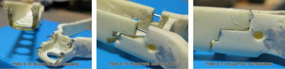


-
FISD E-11 BLASTER REFERENCE
FISD E-11 Reference Team replied to FISD E-11 Reference Team's topic in ANH BlasTech E11
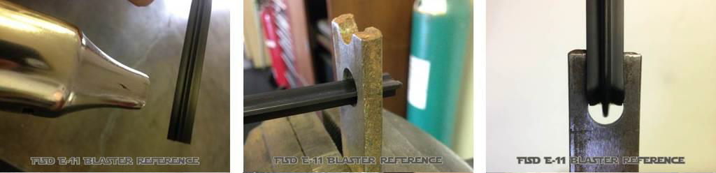
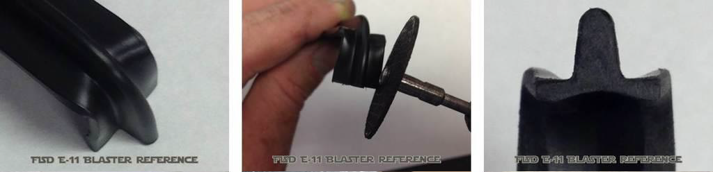
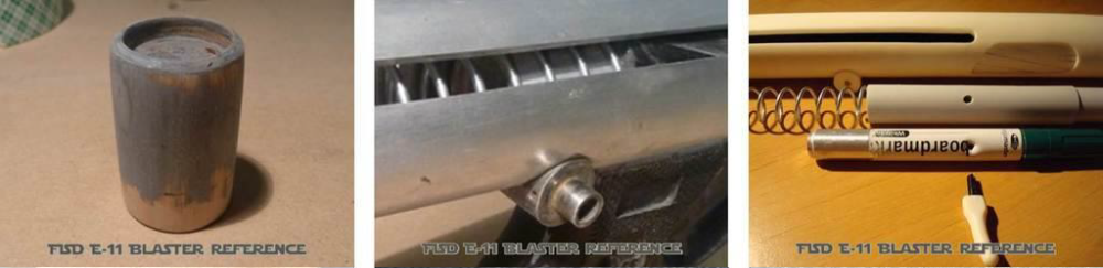
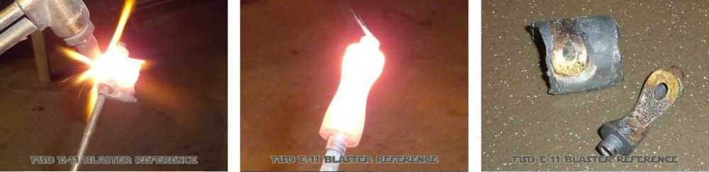
#12 - The T-Tracks When doing a pipe build, you will need T-tracks to cover the venting holes in the receiver tube. Although there are 8 rows with holes, you will only need 6 tracks at 7.5 inches in length. The bottom row and the row with the bayonet lug should not be covered. Tracks should get heated for easier bending with a heat gun or hot water (almost boiling). If the bends are angled a bit less than 90 degrees, this will help to keep the tracks in place. Additional support can be achieved with glue. You might have to shape the ends of your tracks to fit into the venting holes. Gloves are recommended for working with parts at high temperature.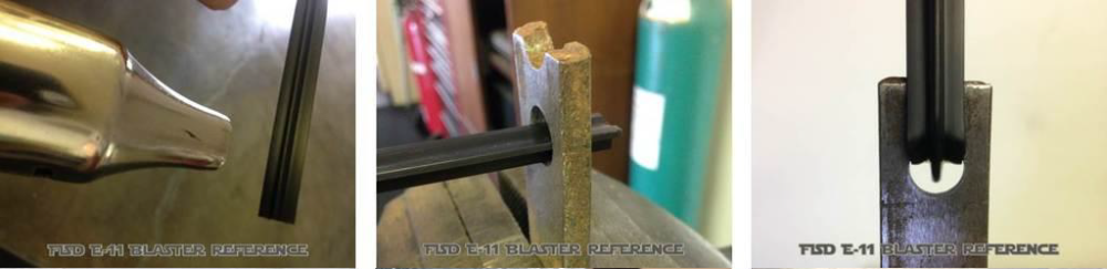

-
FISD E-11 BLASTER REFERENCE
FISD E-11 Reference Team replied to FISD E-11 Reference Team's topic in ANH BlasTech E11
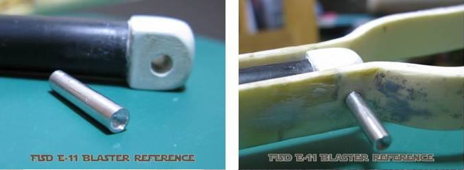
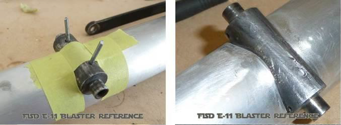
#11 - The Bayonet Lug Check reference pictures and make sure to install your resin part the correct way. A metal pin or a screw from the inside will help keep the lug in place.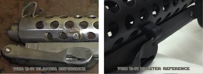
-
FISD E-11 BLASTER REFERENCE
FISD E-11 Reference Team replied to FISD E-11 Reference Team's topic in ANH BlasTech E11
#10 - The Flash Guard There should be two C-shaped guards in your kit. In case these are not the same size, use the smaller one as the flash guard. The following can be used to modify both. Mod A: With a cylindrical sanding bit on the rotary tool these can easily be thinned on the inside, to look more like the real part. For trooping purposes, you might want to leave them slightly thicker for stability. The bend can be adjusted with an iron. For a smooth fit to the receiver tube, wrap sandpaper around the receiver tube and carefully sand the gluing side of the guard to fit snugly. This will ensure the base of the guard matches the exact surface contour of the receiver you are gluing it to. Mod B: Alternatively the guards can be scratch build from a sheet of plastic or metal (no pictures available).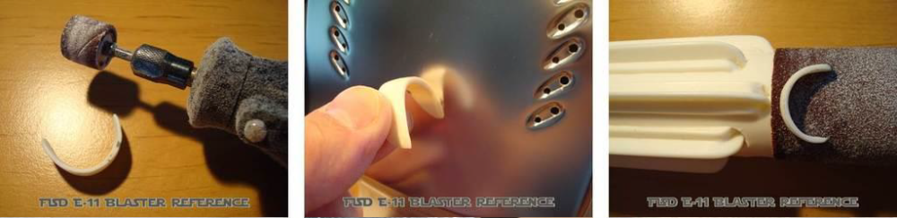
-
FISD E-11 BLASTER REFERENCE
FISD E-11 Reference Team replied to FISD E-11 Reference Team's topic in ANH BlasTech E11
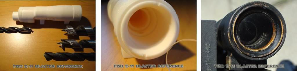
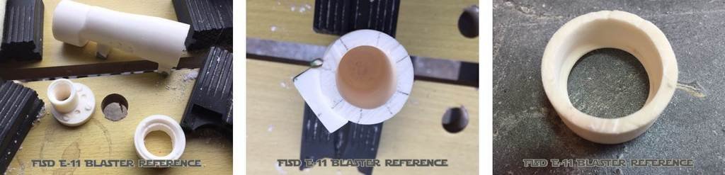
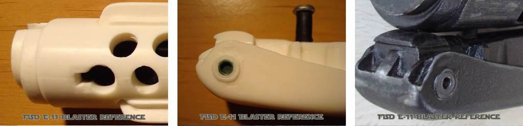
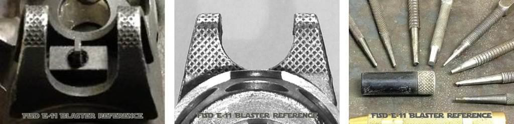
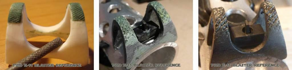
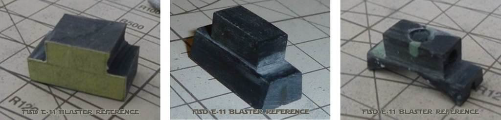
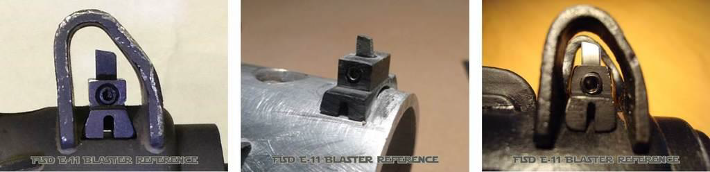
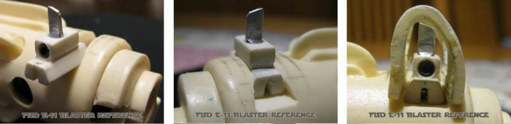
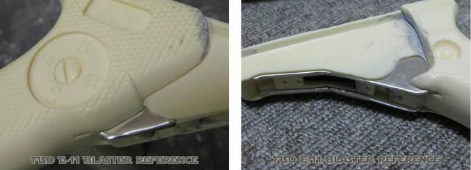
#09 - The Front Sight Mod A: To recreate the visible part of the front sight pin, use a 2mm piece of plastic or metal and shape the top like the real part. Mod B: If you plan for very high accuracy on the whole front sight, the pin can also be completely scratch built from aluminum,a threaded rod or a long screw. Mod C: Depending on your kit and the accuracy you strive for, you might want to cut/separate the front sight block from the sight guard. Mod D: The original guard has a knurling pattern. This can be replicated onto your resin part using a thin layer of modelling clay. Before the modeling clay sets, simply imprint the knurling pattern on the guard in one careful pass. Check your tools for knurling patterns that you can use for this. Attention: this pattern does not cover the full surface of the guard but starts/ends different on the front and rear side! Refer to the photos below. Mod E: For some kits, you will now have to recreate the front sight block to sit onto the receiver tube and hold that pin. The pin can now be inserted and both sides of the block can be slotted like the original part. The small grub screw is inserted from the right side to hold the pin. Mod F: The front sight block from the real Sterlings rests in a dovetail channel. This can be carved into "full resin" receiver tubes. Pipe builders can use modeling clay inside the pipe to recreate this slot. A different front sight block is required here, as it no longer sits onto the receiver tube, but slides into the dovetail channel.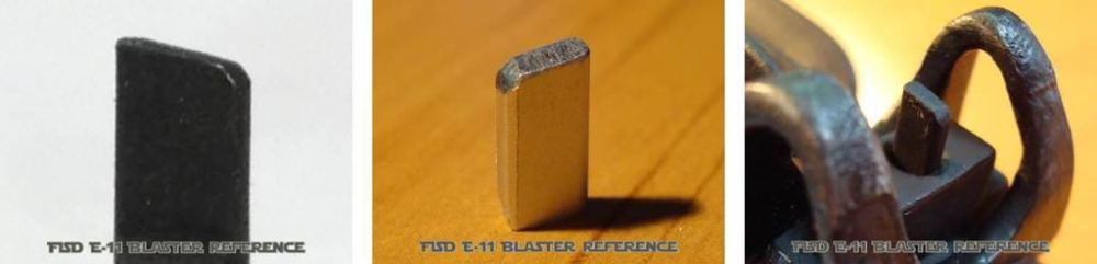


-
FISD E-11 BLASTER REFERENCE
FISD E-11 Reference Team replied to FISD E-11 Reference Team's topic in ANH BlasTech E11
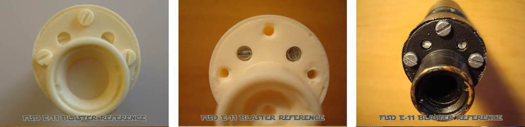
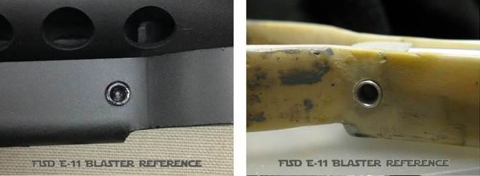
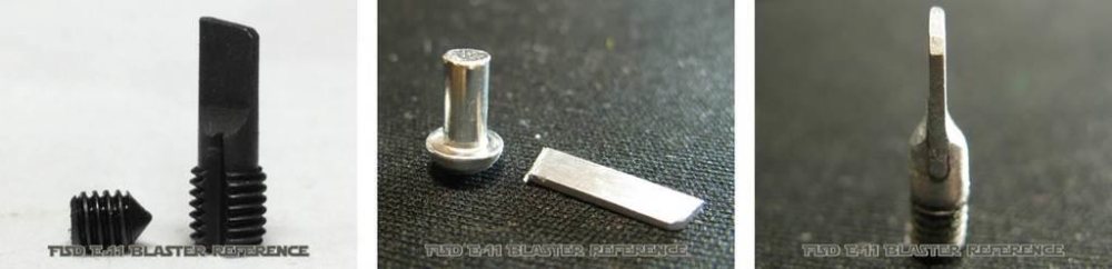
#08 - The Muzzle And The Screws For a pipe/tube build, make sure the front muzzle is installed correctly. Remaining gaps to the receiver tube can be filled with modelling clay - only if you do not have to remove the muzzle anymore to install other components! Resin muzzle screws can be replaced with real ones. The original hex screws do have a crosshatch knurling pattern. -
FISD E-11 BLASTER REFERENCE
FISD E-11 Reference Team replied to FISD E-11 Reference Team's topic in ANH BlasTech E11
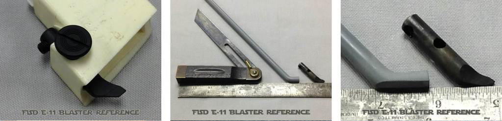
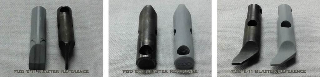
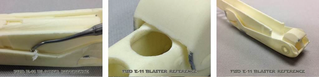
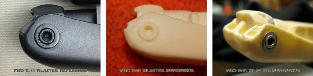
#07 - The Selector Switch Mod A: The selector switch is at high risk to break off, so stablilization is mandatory. An installed nail, screw or 3.5mm stereo headphone jack works fine. If not glued, the part will remain moveable. Mod B: For a "clicking" selector switch, you will need an electrical rotary switch, small enough to fit into the hollowed area in the grip. Try to get one matching the three switch positions on the grip. Once installed, openings can be sealed and disguised with modeling clay.
-
FISD E-11 BLASTER REFERENCE
FISD E-11 Reference Team replied to FISD E-11 Reference Team's topic in ANH BlasTech E11
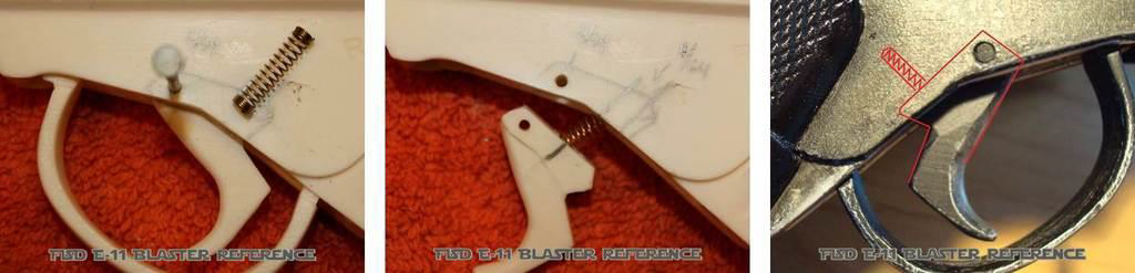
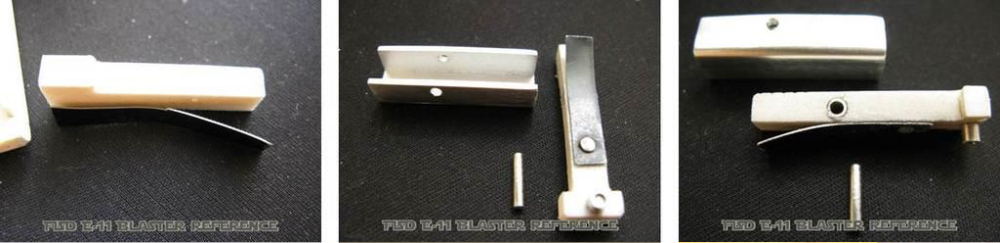
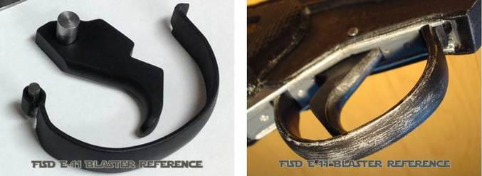
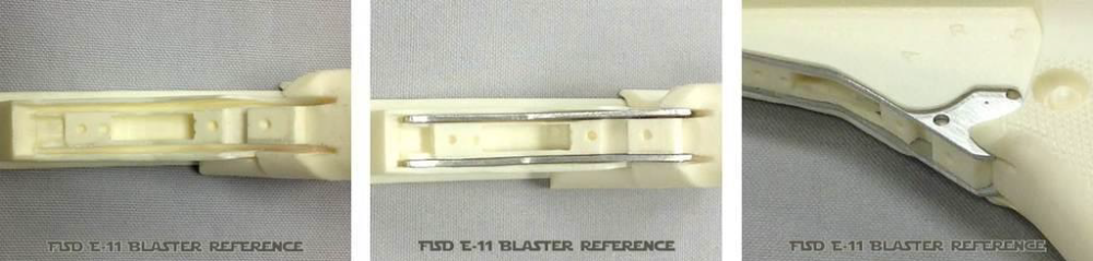
#06 - The Trigger And Guard Mod A: A moveable trigger can be achieved with a simple nail and a spring from a ballpoint pen. Check original Sterling references for placement of the trigger and mark this position on your grip. Drill holes for spring and nail. Shape the trigger to fit into the slot. The trigger guards from real Sterlings were made from metal strips, bent to shape. Make sure to install your resin trigger guard the correct way. It will then also cover the head of the first support screw in the grip. Alternatively the guard can be made from a metal strip; aluminum being the easiest to form. Mod C: Some parts from the trigger group can be covered with very thin aluminum sheets, or you can completely recreate them.
-
FISD E-11 BLASTER REFERENCE
FISD E-11 Reference Team replied to FISD E-11 Reference Team's topic in ANH BlasTech E11
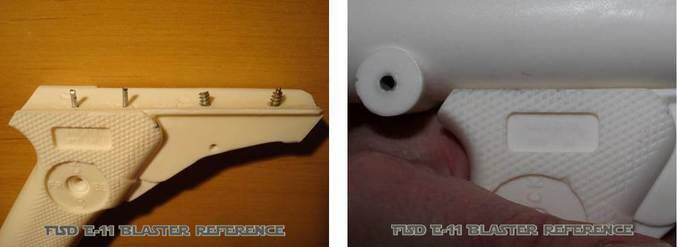
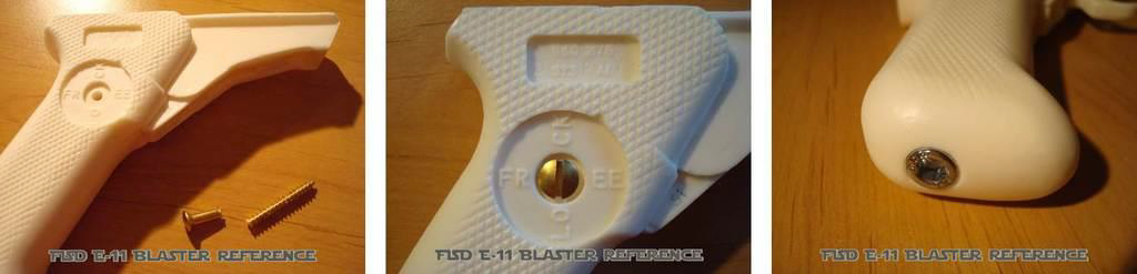
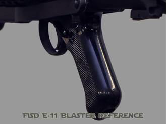
#05 - The Grip Mod A: Replace resin screws with real screws. Select a drill bit just a little bit smaller than the new screw and drill a center hole. Then use an electric screwdriver to install the screw. The threading will cut into the resin and provide a tight fit. Do not force the screw into the material. If needed, pre-drill a slightly bigger hole. Mod B: Add metal pins and screws when attaching the grip to the receiver. This will provide added support to the grip for carrying the weight of the fully assembled blaster. Only gluing or applying epoxy to connect the grip may result in the top half of the blaster to break off. Attention: Do not place the grip next to the folding stock hinge. Leave a gap of about 4 mm. Mod C: With a hat nut you can replace another resin part in the grip. Be sure to close the small gaps around it with modelling clay.