


Shrapnel
-
Posts
60 -
Joined
-
Last visited
Content Type
Profiles
Forums
Gallery
Articles
Media Demo
Posts posted by Shrapnel
-
-
5 hours ago, The5thHorseman said:
The reason why I recommand to print the textured pads standing is because the top surface isn't actually flat but very slightly curved instead. And the best way to really capture that shallow curve is to print the part upward, otherwise the print resolution (even at 0.1mm) will mess up with it.
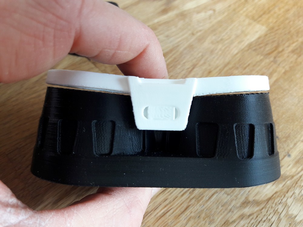
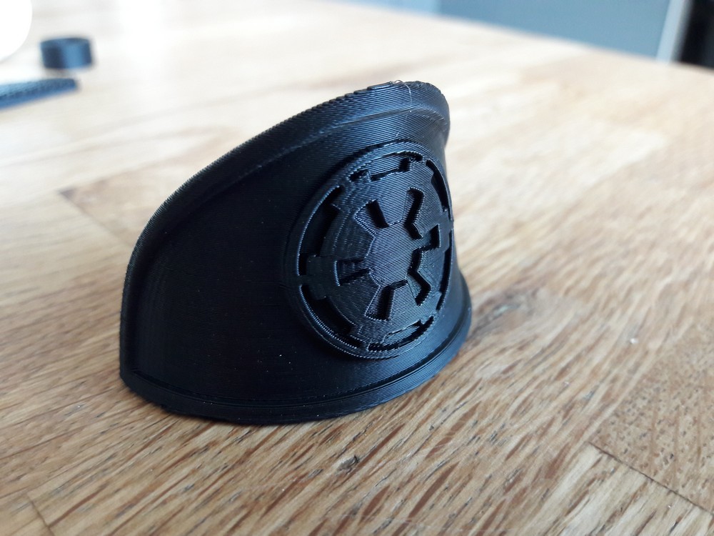
And yeah, why that Imperial cog instead of the First Order crest? I don't know, but it's there, no doubt about it. Probably an easter egg from the propmakers ;).
Thanks for the feedback about the threading issue. I must say I'm kind of bummed that it's too tight. I have used a 0.5mm clearance for that threading which is kind of large but apparently that's still not enough. Like you said, you can perfectly get away with it by deepening the thread on the objective ends with sandpaper. I managed to make functional a threading with a tighter clearance this way too, it just takes a bit of patience.
And if really you can't get it to work, I'll update the parts with a larger clearance between the threads.Also if I had to guess, I would say that the small gap between the black and white eyepieces is probably caused by the support filament. But from a design point of view the two should mate perfectly
Anyway, great work so far! And I'm glad to read that the rangefinder works good. It took me some time to find a working solution I was happy with, and as I didn't test it either I could only hope it would work. Especially since they didn't bother to make it functional on the original prop.
Some replies:
- the textured pad - I noticed the slight curve but hadn't realised that was why they were vertical. Nice idea.
I'll try printing them again, see if I can capture more detail. Thanks for the tip!- the imperial cog... I had not noticed that they were on the actual props. Good spot - so the First Order is re-using a load of old imperial tech!
- the threads - yeah, I have no idea what to suggest. I'm new to 3d design (I started learning 123D last week so I could print a scope for my megablaster - more details on that later) and the one thing I've discovered is that I need to be very careful with measurements when mating one part to another, to allow some clearance but not too much.
- black/white eyepieces - after staring at that photo, I'm starting to think that you are right, that the shape underneath is caused by the support structure. Which means, when compared to your design screenshot, that I should be able to sand the underneath to create the right surface to mate with the black part. Good to know.
I have a little upgrade to the binocs on order - I'll post photos after it's arrived and I've installed it
")
-
On 24/03/2018 at 1:15 PM, The5thHorseman said:
Have you tried the threading between the front objectives and the binoculars body? Because getting the right clearance for it to work with FDM printing can be troublesome and as I was out of filament I never tried it myself to see if it works.
One word of advice though, when you try it, if the pieces start to get stuck do not force or they'll get dead jammed together.
Hi Germain,
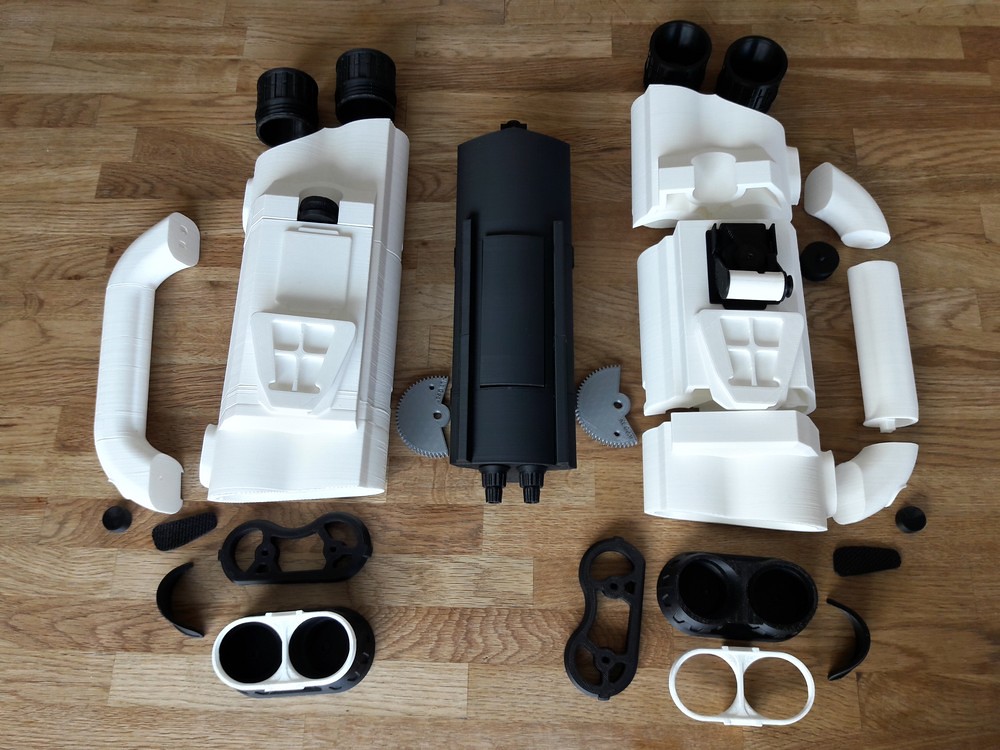
I've printed out your quadnocular parts (great design work, and thank you).
My objectives thread will not mate with the thread in the binoculars body. Very tight, I can get one or two of them about 1mm in before they start to jam.
As mentioned in my build topic, I'm going to try sanding the thread on the objectives to reduce the diameter of the thread.
Hopefully that should work. -
A couple of other points.
I also printed the thumb pad horizontally - it seemed logical.
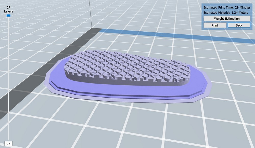
And they came out ok.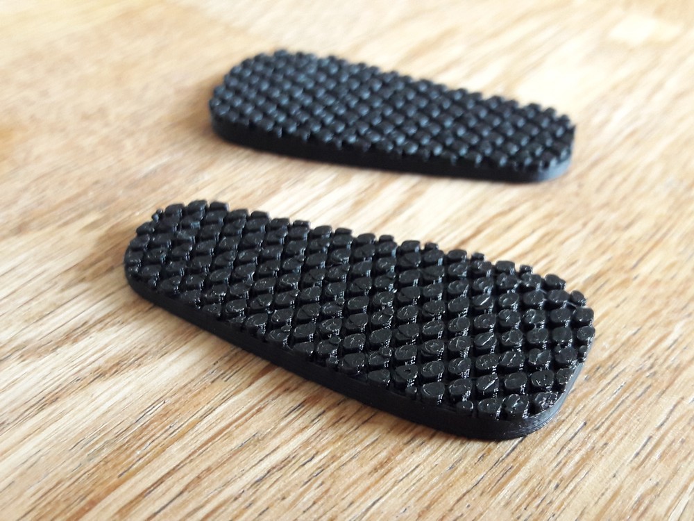
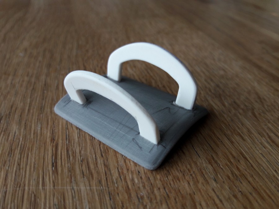
And the handle kit:
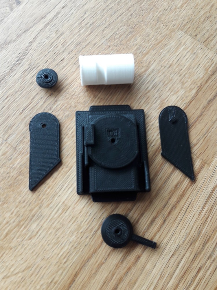
Which was fun to build...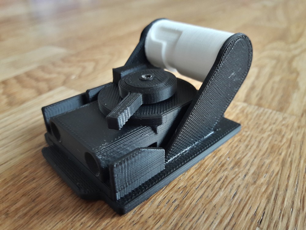
Next up is to start filling the joins then sand and bondo and sand again to prepare the surface of the left and right white binocular parts for painting.
-
Some other points about the design:
The vast majority of the parts fit perfectly. Great design work.
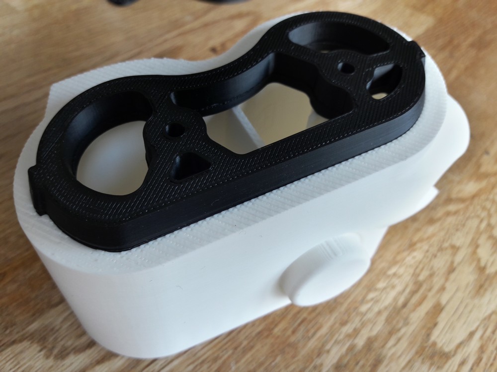
The white eyepieces - I rotated these and printed them horizontally.
Two reasons: firstly, it meant that all the support structures were underneath, where the marks they leave would not be visible.
Secondly, the upper surface is finished nicely by the printer in a horizontal position like this.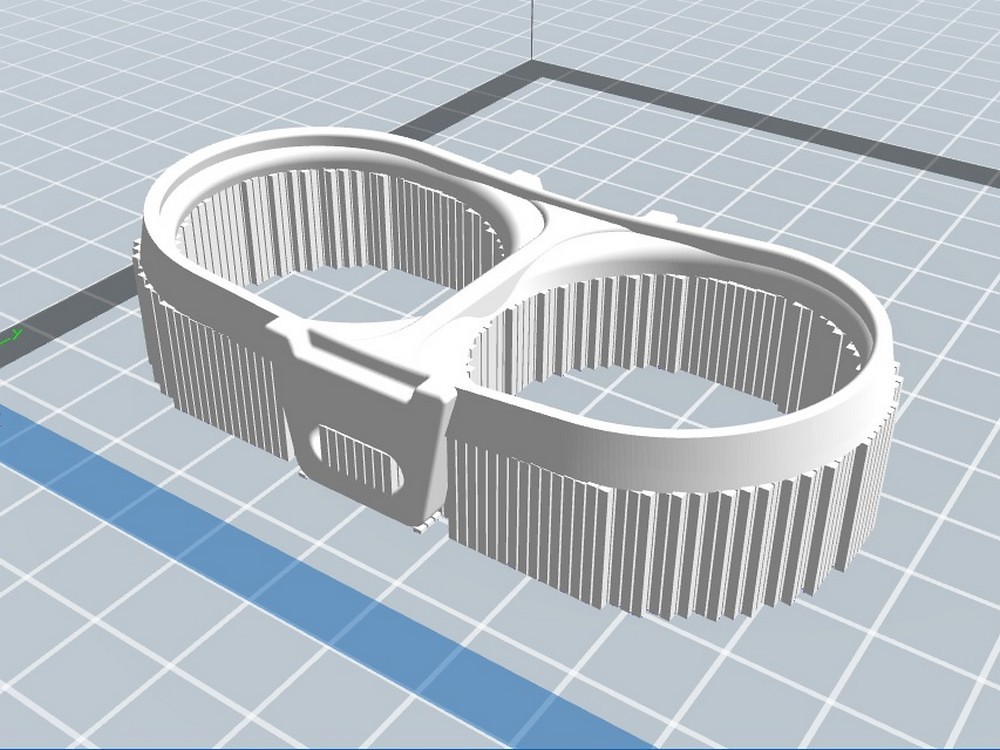
I'm not sure if this is a result of the printing (above) or a slight kink in the design. Either way, my parts have a very small gap between the white and black parts of the eyepiece. Again, this is not a big deal and I will fix this with careful application of heat to gently bend the PLA into position.
I printed the objectives with no supports (listed optional) and they came out great.
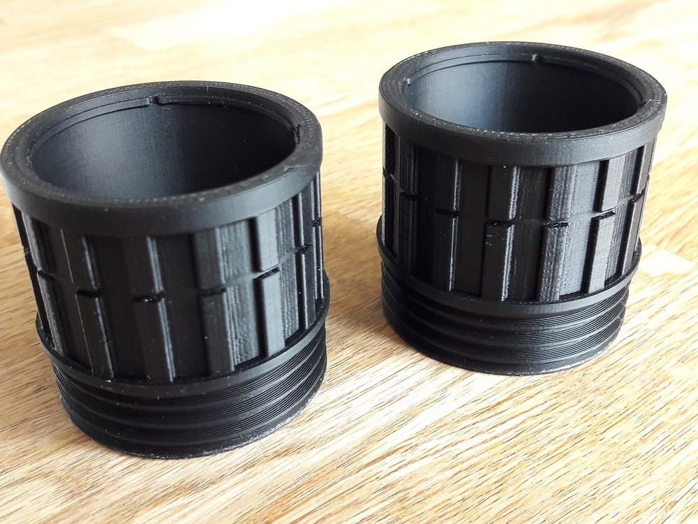
Unfortunately, with my prints, the objectives' thread did not fit into the screw thread of the binoculars body.
Yes, I read Germain's note about the direction of the threads :-)
Very very tight fit. One of them, on the right side, does begin to screw in but then jams after a mm or so.
Plan is to try sanding the threads on the objectives to reduce the diameter then try again.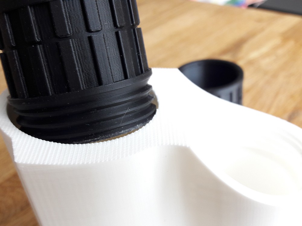
-
First up - thanks to Germain. These files are amazing, compliments on a really great design.
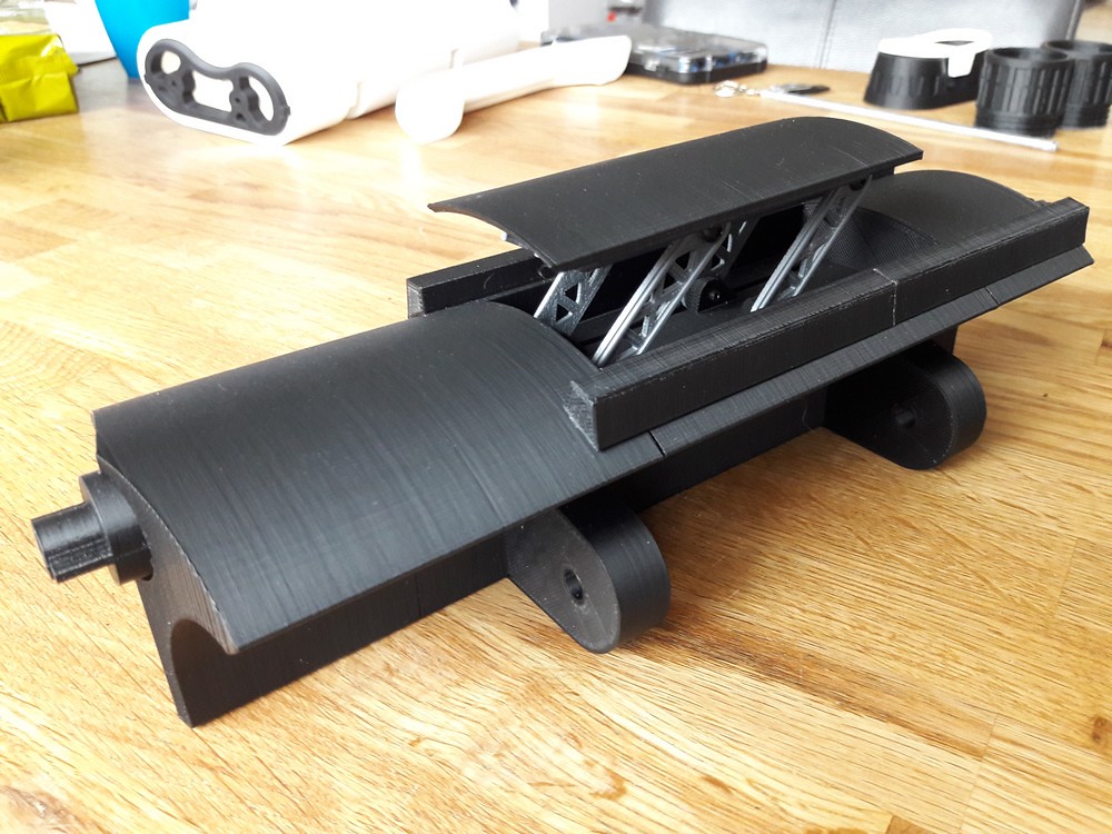
I've got a small printer - a Flashforge Finder - with a 14cm cubed print bed. It makes great PLA prints but I do have to get creative with extra slicing to make large items fit the small print bed. I printed out all the quadnoculars parts over the last 6 weeks or so, with only a couple of misprints. Surprisingly, the black prints look much much nicer than the white, although I wonder if that is because shadows and thus lines are easier to see on the white.
The quality of the Germain's design is exceptionally high.
My printer, however, does create a sort of stepped surface when printing almost horizontal planes. These will be sanded out in the finishing process.
The bulk of the parts were printed at 0.18mm per layer.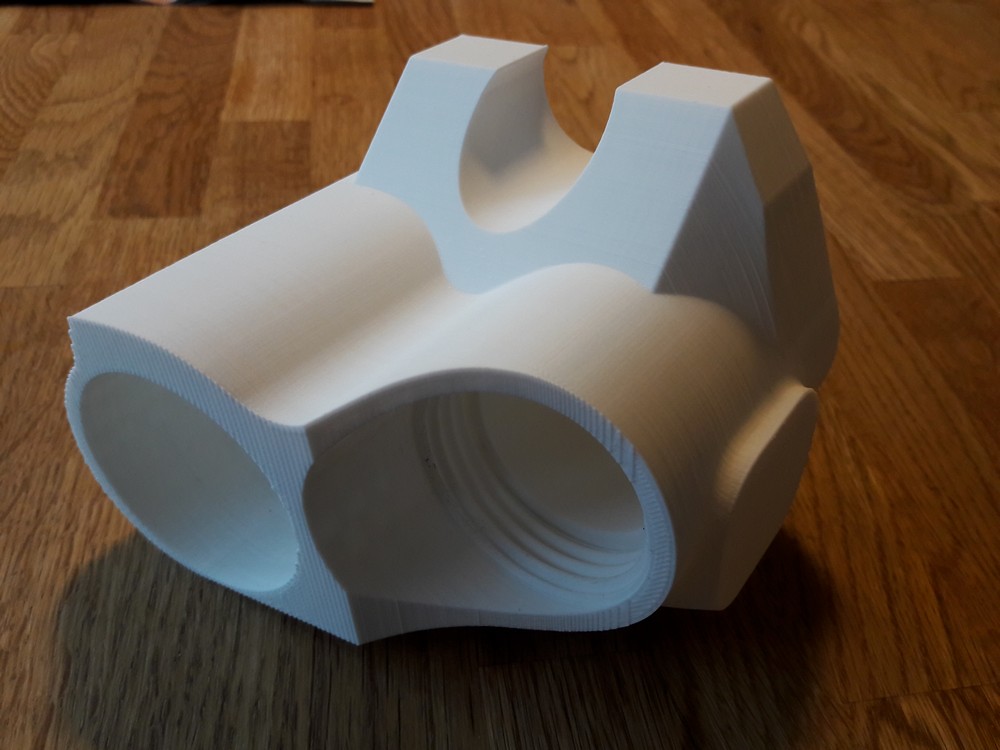
The black hinge was printed first and was straightforward to put together, mostly thanks to Germain's excellent instructions.
I love the functionality of the range finder.
The front and rear sections with handle mounts were too large for my printer so I had to slice off the handle mounts and print separately.
I don't see this as a big challenge - the white body needs to be filled, sanded and painted anyway due to being printed in 3 sections.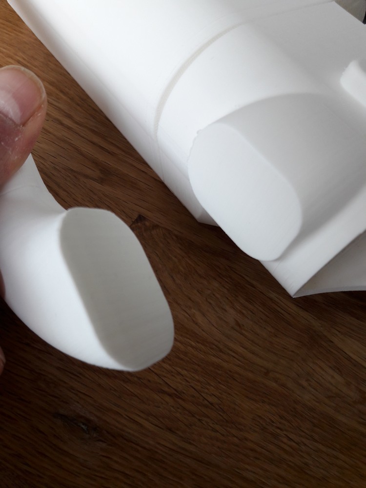
Photo showing the print lines on the white body parts.
I think temperature plays a part in creating smooth PLA prints - when I starting printing the first white blocks back in Feb, it was cold and I would ventilate the room by opening the window. These first parts showed a lot of uneven print lines. Since reading more about PLA online, I've tried to stabilise the temperature around the print job and to keep it warm. I now keep the window closed and have enclosed the sides of the printer with plastic sheeting. I've even made a roof for the printer to keep in warmth and I keep a light pointed into the print space to add warmth. The increased temperature is noticeably - probably around 30 deg C - and print jobs now appear much smoother.
I will be filling joins, sanding and painting so this is not a really big deal.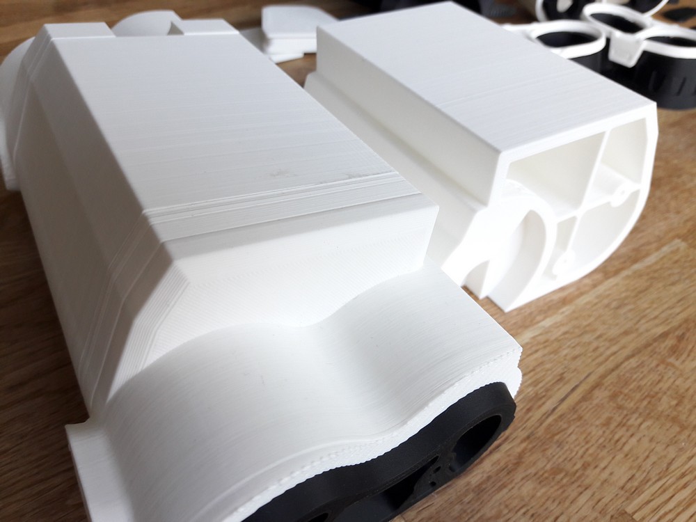
Top tip for putting the body parts together (from my gf!) - jam the screws onto the end of a long wooden skewer, then lower them into place inside the body before securing.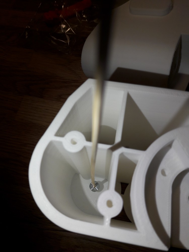
I love these small details... but I do have to ask - why an imperial cog and not the FO logo?! ;-)
-
Just found this thread - compliments on your design skills but, most of all, you did a beautiful job of finishing and painting the pack.
-
Voted!
-
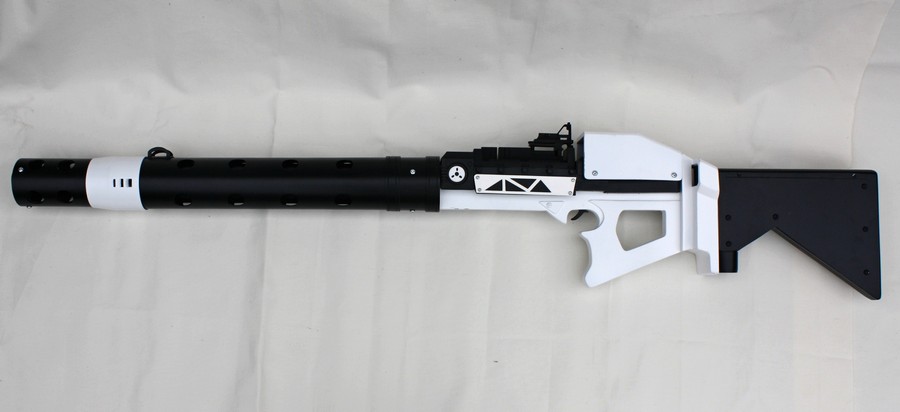
Some photos of the megablaster so far. At some point I'd like to add a scope and maybe stand, but the project is on hold over summer due to holidays and other commitments.
.
-
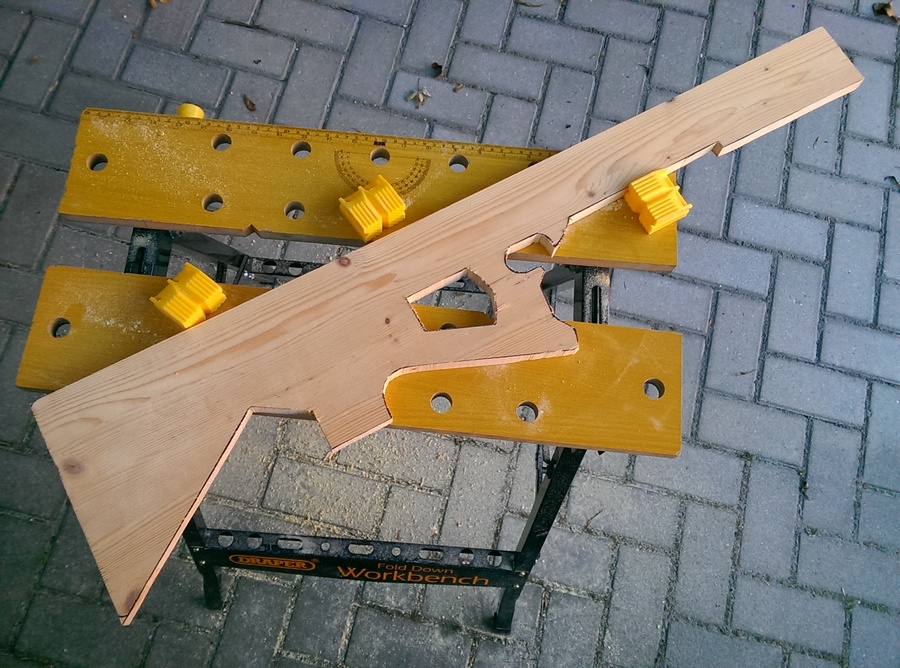
Progress so far...
The bulk of the build is complete. Still working on the area between the stock and the trigger - need to complete some details there, then bondo the area and get it ready for painting.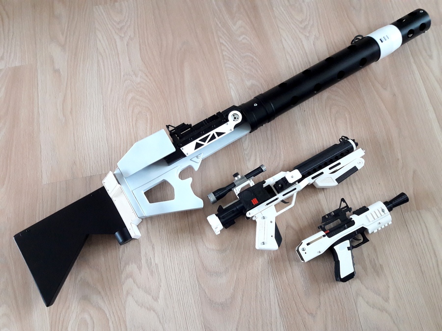
-
 1
1
-
-
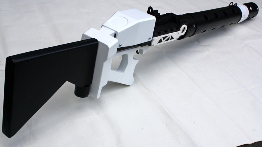
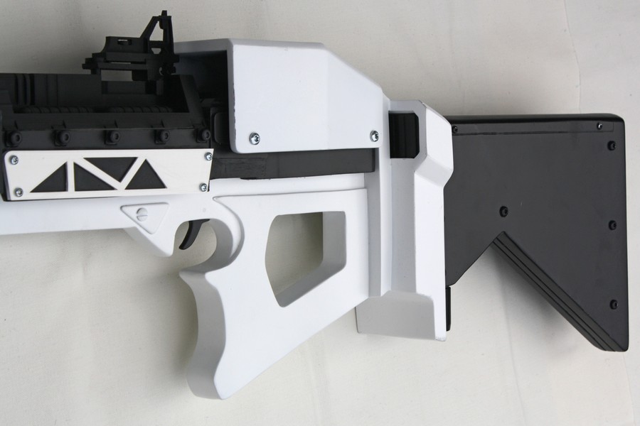
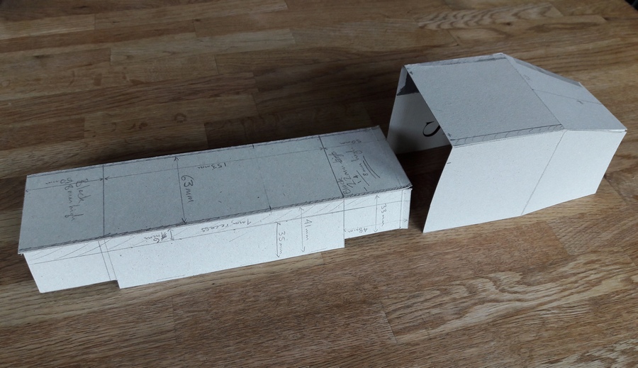
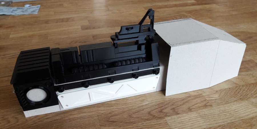
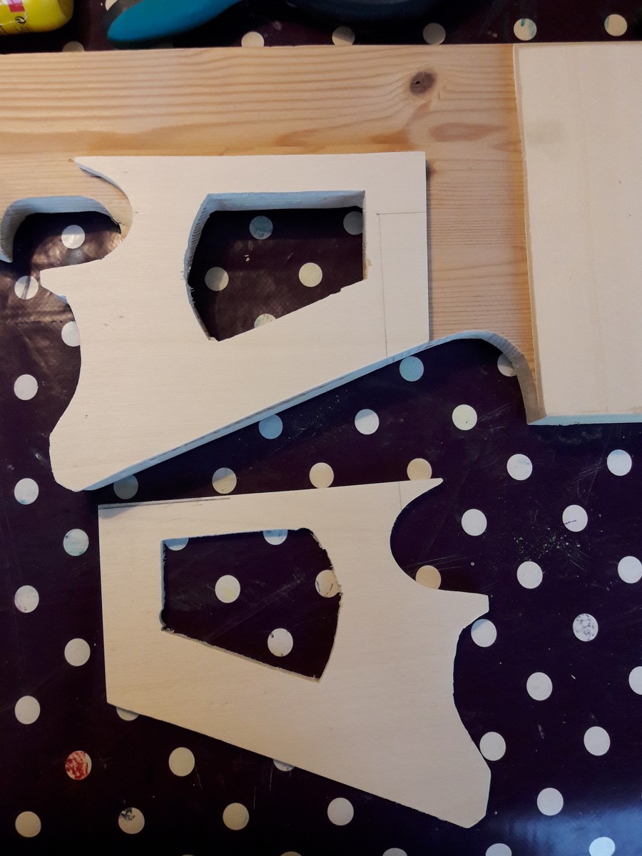
Got busy this week cutting and building the angled shapes between the trigger and stock. What I call the vent boxes.
Using my Sketchup build, I made a cardboard model of the vent box area.
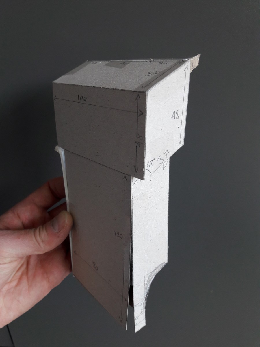
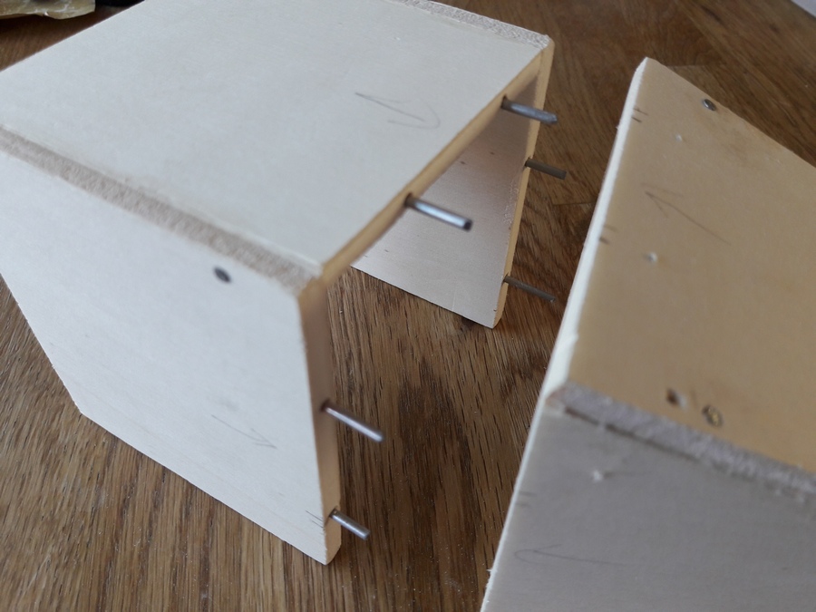
Based on these dimensions, I cut out all the parts required from 6mm multiplex wood.
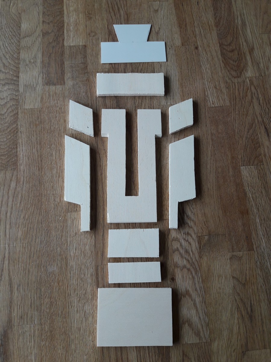
Then glued and nailed it together.
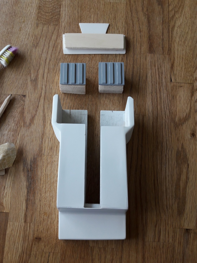
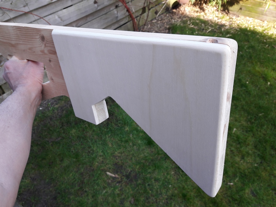
I designed it with a groove cut through the middle so it slides onto the blaster body as one component.This means that the flat plate at the bottom is one solid piece with no cuts or joins. Just creates a neat and tidy finish.
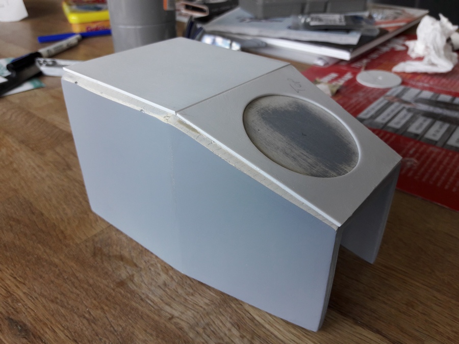
A top plate cut from plastic will then be bondo'd over the top.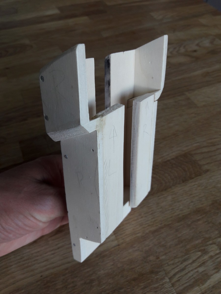
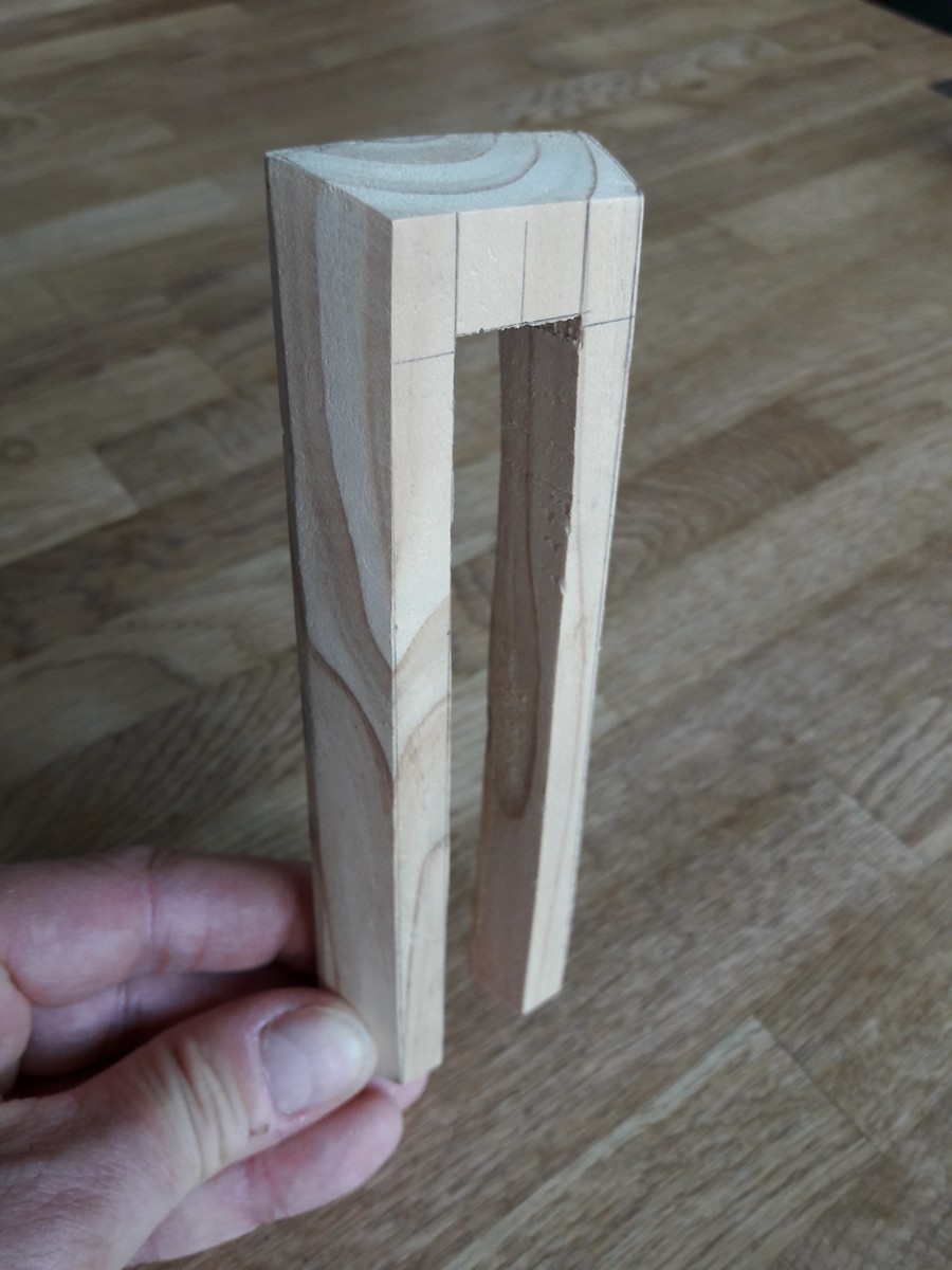
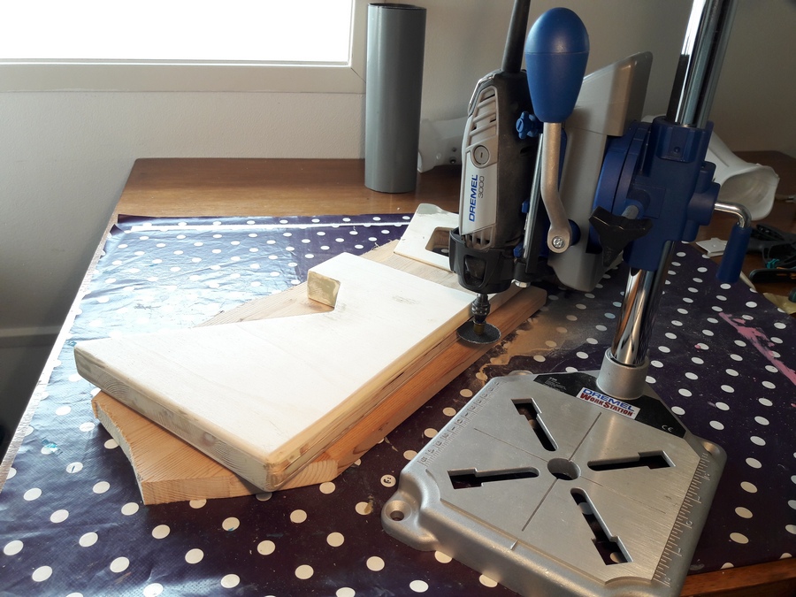
There is a small angled block between the vent boxes and trigger area. I cut and shaped this from one block of wood.
As with the vent boxes, I cut a groove through the middle so the block slides onto the blaster body.
.
-
1
-
-
I actually got to look at a photo of a screen-used vest laid out on the ground, so the details of the straps were quite clear.
Here's a photo I took while making my straps - hopefully it shows enough detail.Left of the measuring tape are the parts you need. Measuring tape is in CENTIMETRES!
Right of the measuring tape are the finished straps.
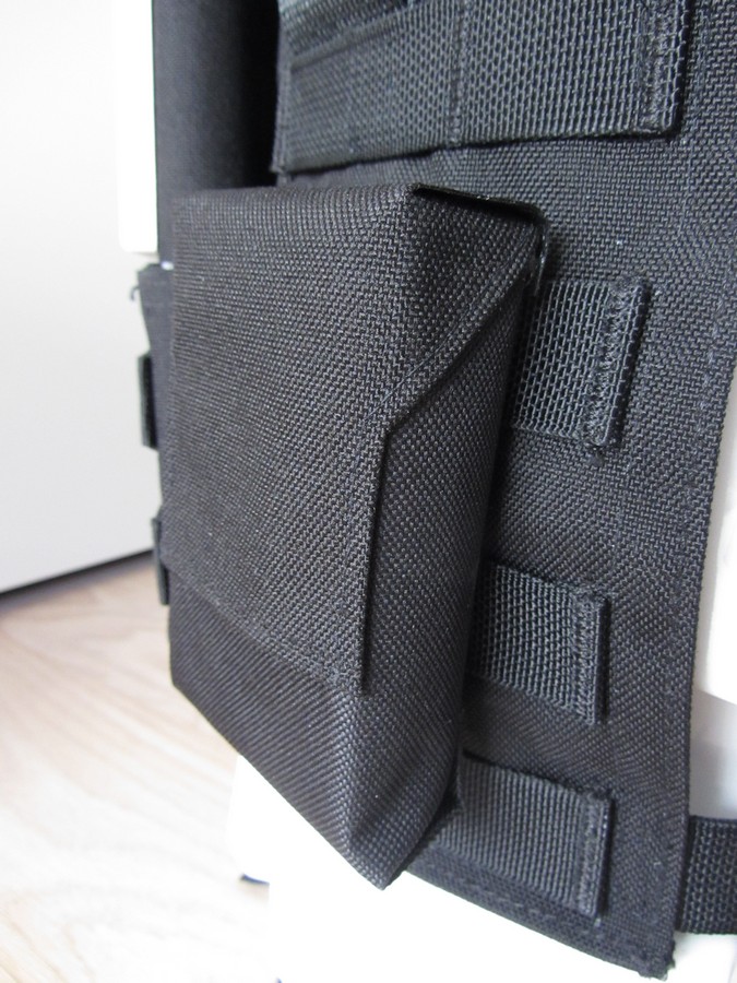
And a close up of the vest:
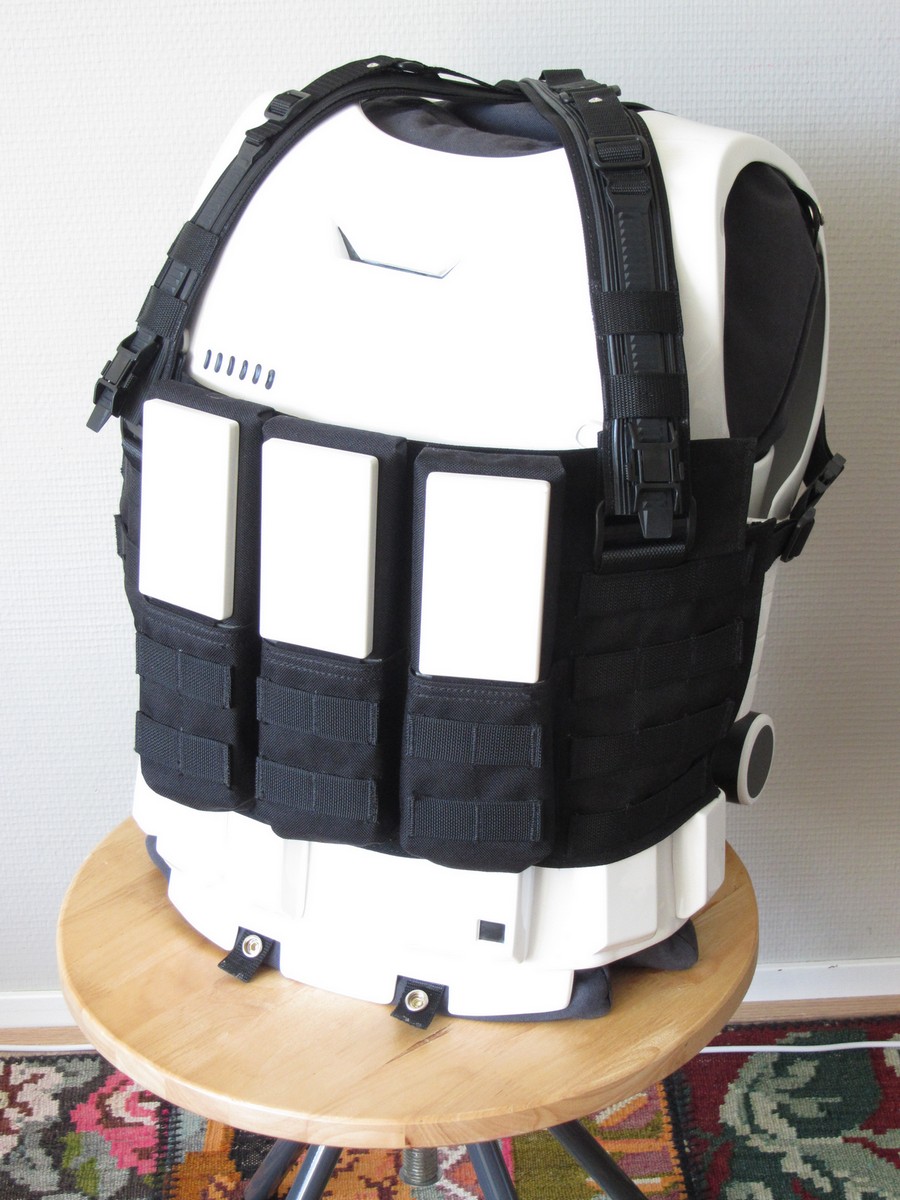
Pouches (although I heard they are supposed to have elastic across the front)
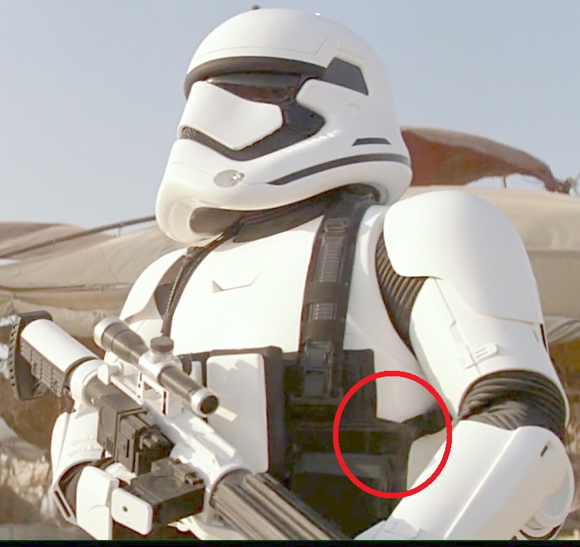
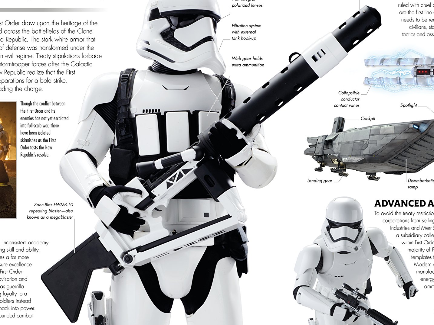
And just for the record... screenshot from TFA...
-
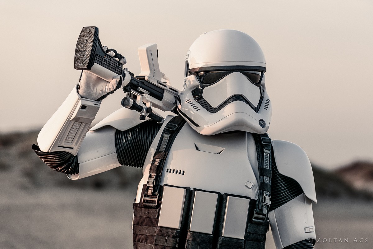
I made 5 heavy weapons vests last year. Your best bet is to get a Flyye Law ENF vest via ebay, take it apart and convert it. I can send some instructions if you're interested - it is a little time-consuming but it's not hard to do. Just some measuring, sewing and riveting.
Here's a photo of me and my vest. I've upgraded it with side pouches since this photo was taken.
-
3
-
-
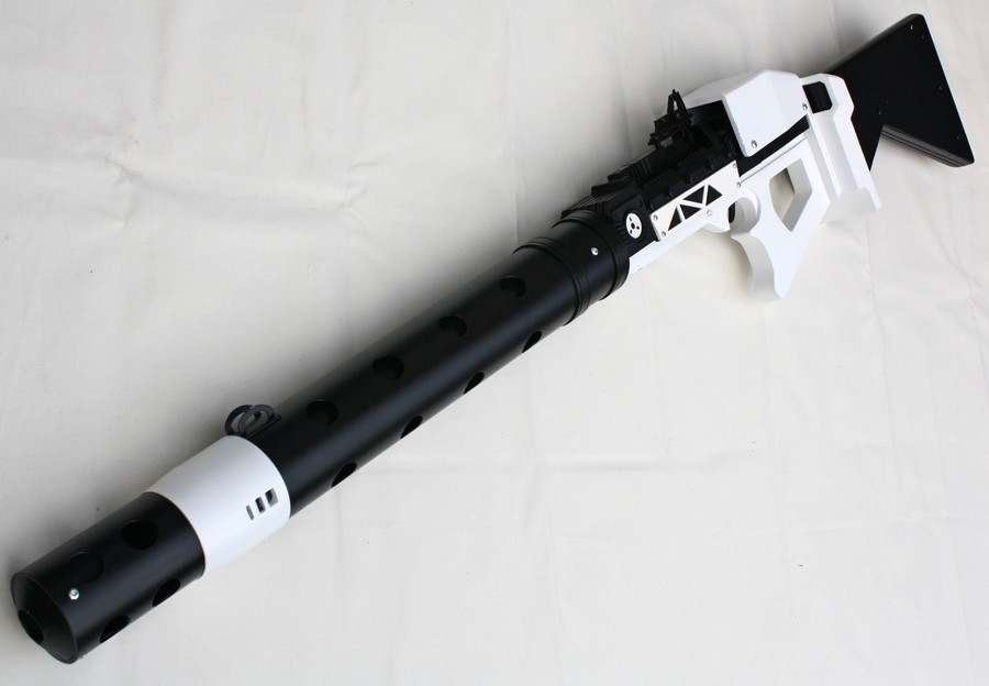
Just got the barrel finished. Now working on the boxy vent part behind the trigger. Hope to get that finished this week.
-
Hi Carlos,
Are you in the FB FO stormtroopers group? Thought I saw your name there a while back.
Anyways, here are the dimensions I used. They are all estimates. What I did was measure the size of my FO thigh armour in real life. Then, using the photo of the heavy weapons trooper in the TFA Visual Dictionary, I measured his thigh armour in millimetres. Divide one by the other to get a conversion number. Then I measured the blaster in the Visual Dictionary photo and multiplied by the conversion number to get a real-life size estimate.
All sizes in millimetres.
This was my plan, but some measurements got adjusted here and there as I went along.
-
1
-
-
Wow that looks great. <br>
And the weathering finishes it perfectly. <br>
Was your daughter happy with it?!
-
1
-
-
EDIT... photo moved to previous section.
-
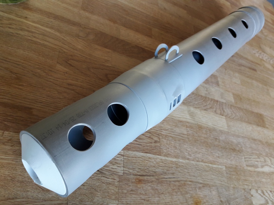
And got the barrel put together over the last couple of days:
The white cone-shape for the muzzle was made from craft foam, after experimenting with paper discs to get the right shape.
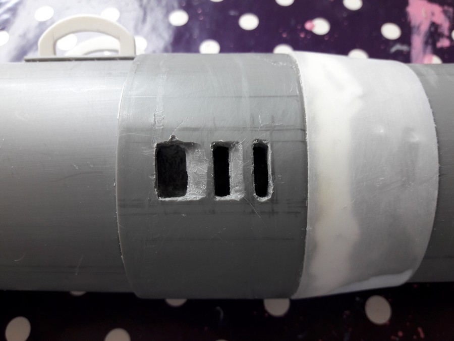
The 3 vent holes on the side were a pita. Lots of dremel work and sculpting with bondo to get decent shapes.
The taper from wide barrel to narrower muzzle was made from a child's plastic cup.
Sights were cut from scrap plastic. I based it on what I could see in the Visual Dictionary but am not sure if the shape is exactly correct.
The finished barrel.
-
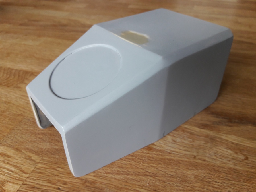
For the top components, I built cardboard models based on the dimensions of the Sketchup model.
Test-fitting Clint's 3D printed parts:
And the finished top module.
I padded out the inside with extra wood, so it just sits tightly on the body of the blaster.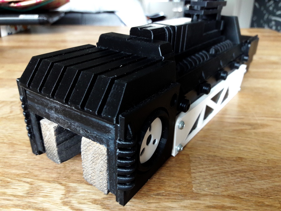
The top box was built using 6mm multiplex wood.
The circular detail was cut using a round 55mm drill saw in 1.5mm plastic.
I then bondo'd all the edges and sanded smooth.
And then after all that thinking, I needed a break so started work on the barrel.
-
First up... thanks to Clint for his great build, his 3-D files and for inspiring me to have a go
So I figured I'd post some photos of my megablaster build. I didn't take that many photos so it's more to show the work in progress than a how-to, but hopefully it adds some extra details about this great BFG.
EDIT: I thought it would be more helpful if I ordered my posts, describing each section as it was built, so I've updated and re-ordered my posts.
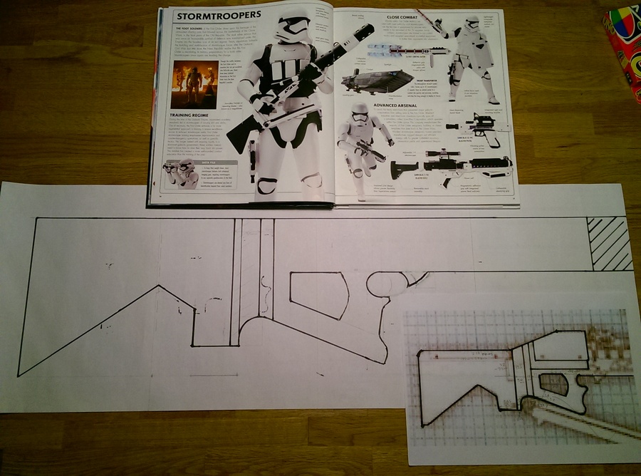
Some research I did on the blaster...- TFA Visual Dictionary - a great shot of the blaster, but not all details are visible.
Here you can clearly see a lot of useful details, such as the sights on the barrel, the barrel vent holes, screw positions on the barrel, the rings around the rear part of the barrel, the trigger, the telescopic monopod behind the trigger area, the grooves around the stock, screws on the stock, plus the overall shape and angles of various elements like the vent boxes behind the trigger area. We can see now with all this extra information the differences between the screen-used blaster and the Sideshow toys blaster.
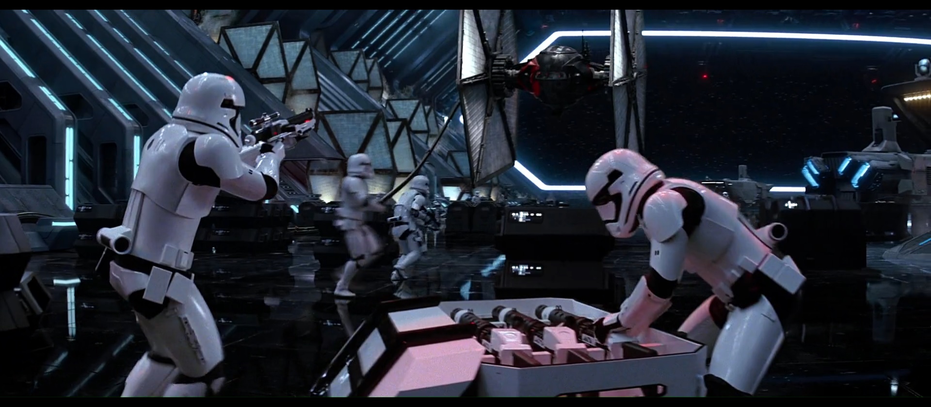
- The megablaster appears a couple of times in TFA. I got the best screenshots during Poe and Finn's escape from the Finalizer.
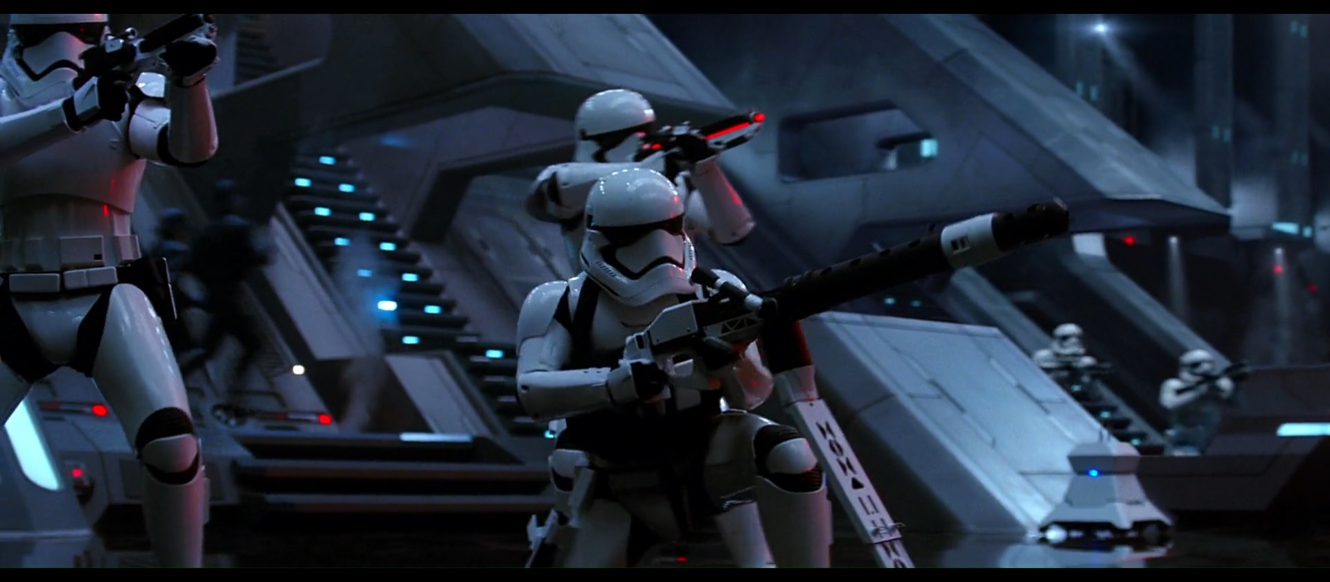
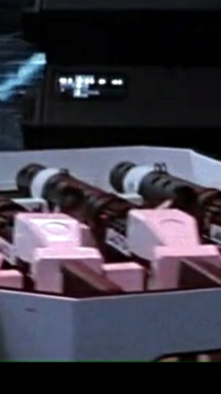
This shot is useful for showing the upper box screw positions, plus more detail on the vent boxes behind the trigger area.
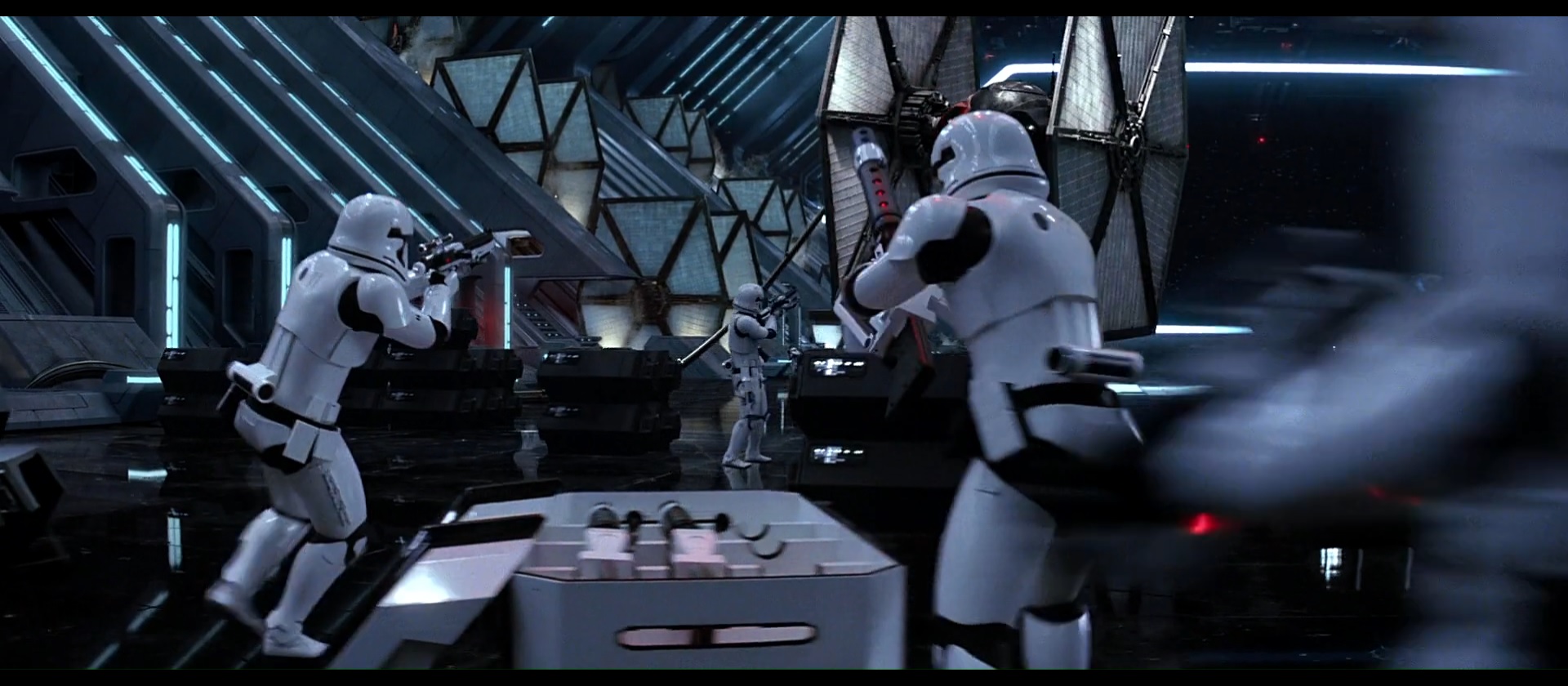
- Screenshot from behind #1
This shot was good for showing the overall square shape of the vent boxes from behind, and also how they only extend out to the side by a small amount.
Also another angle of the barrel sights and the round detail on the upper box.
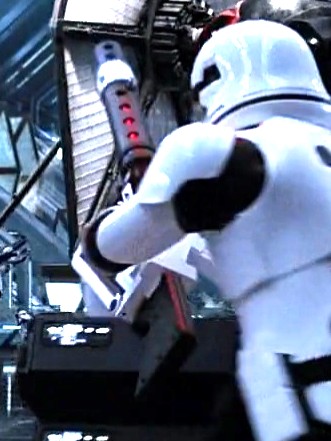
- Screenshot from behind #2
After editing and boosting the contrast, more details become visible. Grooves along the stock and the positions of at least 4 screws on the stock (similar to the Sideshow toys blaster).
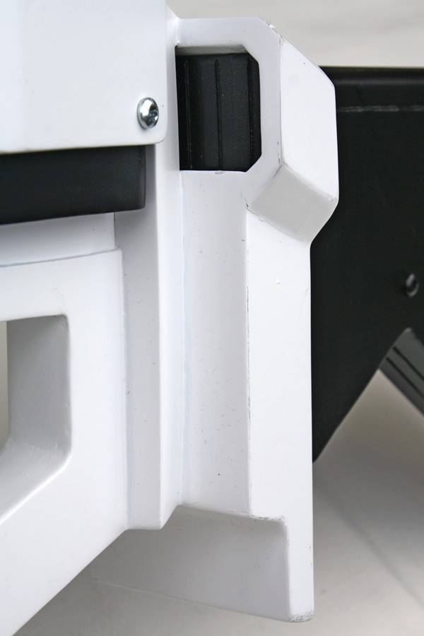
Also visible is a small hole on the rear of the vertical white plate that separates the blaster body from the stock.
I'm guessing that this is a bolt hole to hold the folding stand in place.Also note the inner barrel that can be seen through the 4 holes on the main part of the barrel.
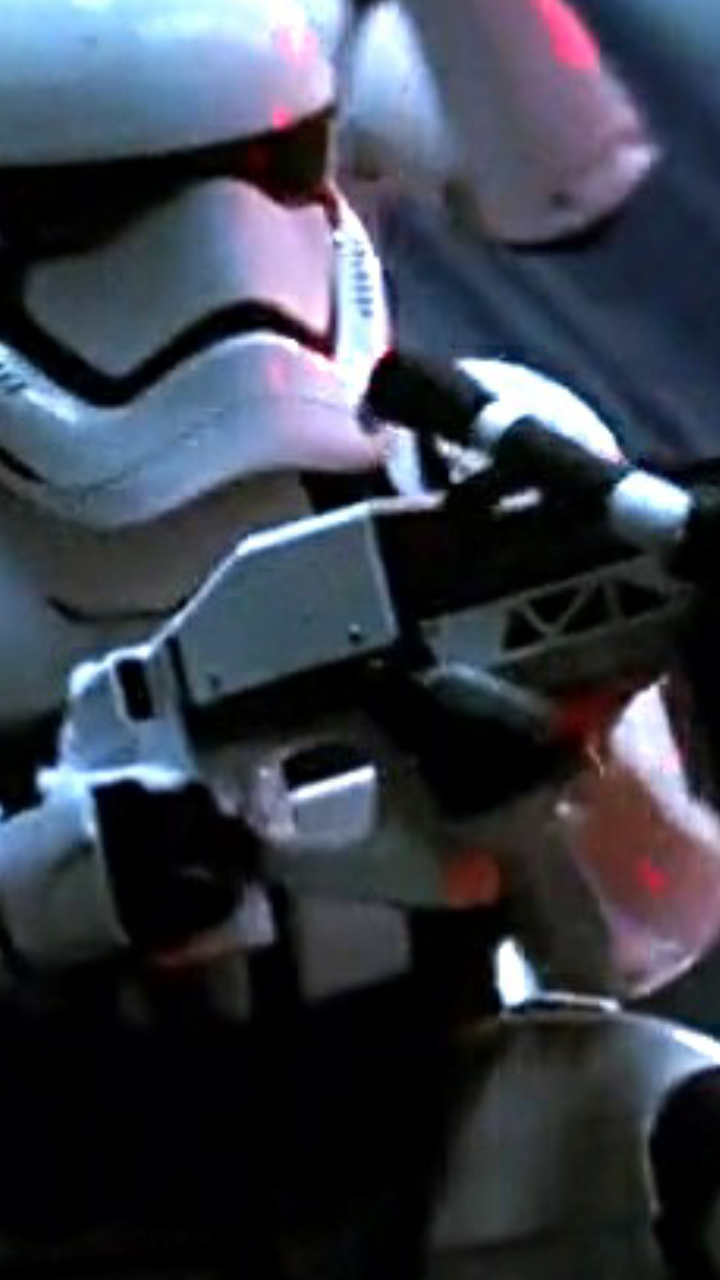
- Firing detail and ?telescopic monopod detail. A good if blurry action shot showing the red lights in the barrel vent holes.
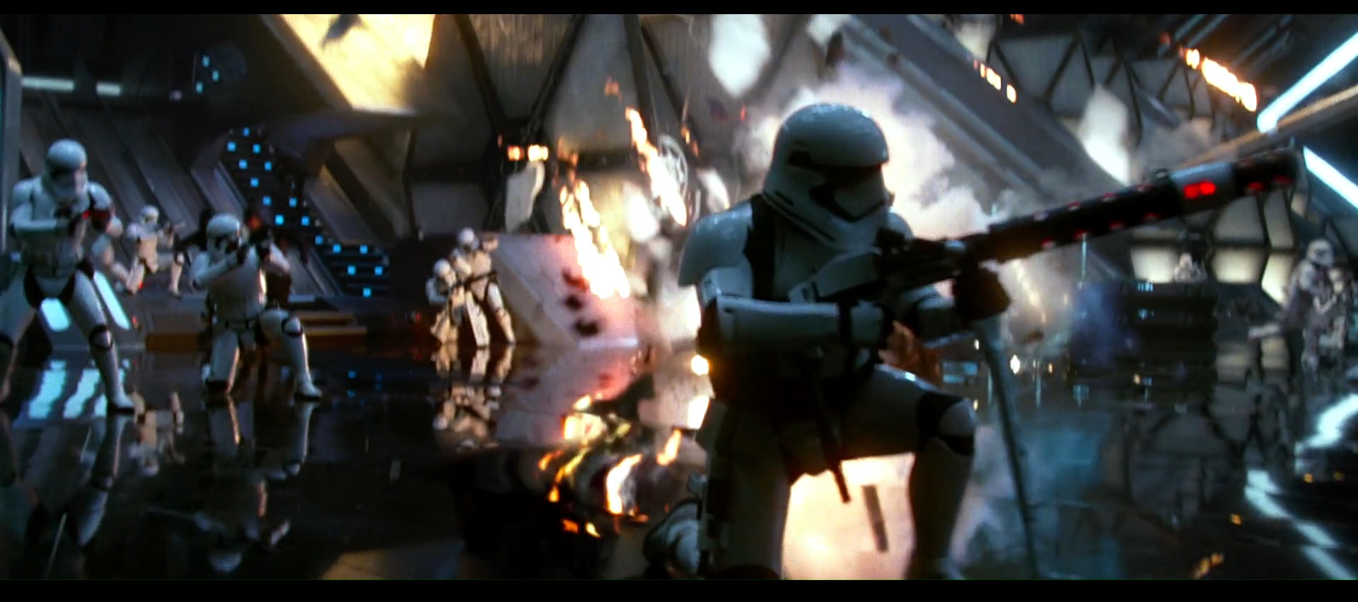
What is interesting about this shot is that it looks like the telescopic stand is partly extended - check the photo below.
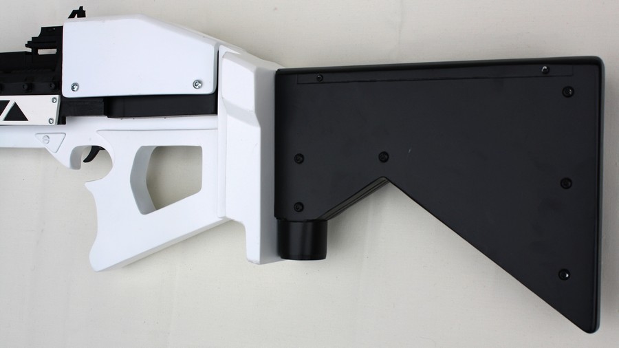
Extending over the trooper's codpiece is a long vertical black bar, which appears to be connected to the stock of the blaster.Compare with the telescopic monopod in Billhag's photo below.
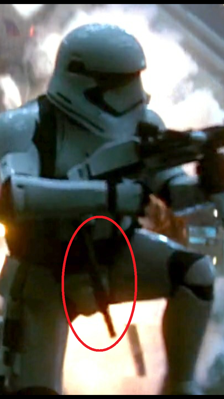
Photo from Billhag showing black telescopic monopod extended from blaster stock:

First thing I did was make some estimates of measurements by comparing the length of my real-world thigh armour to the photo of the trooper's thigh armour in the Visual Dictionary. After measuring the blaster photo, I could scale up these measurements to real-world measurements.
Then I sketched the blaster base life-size on paper:
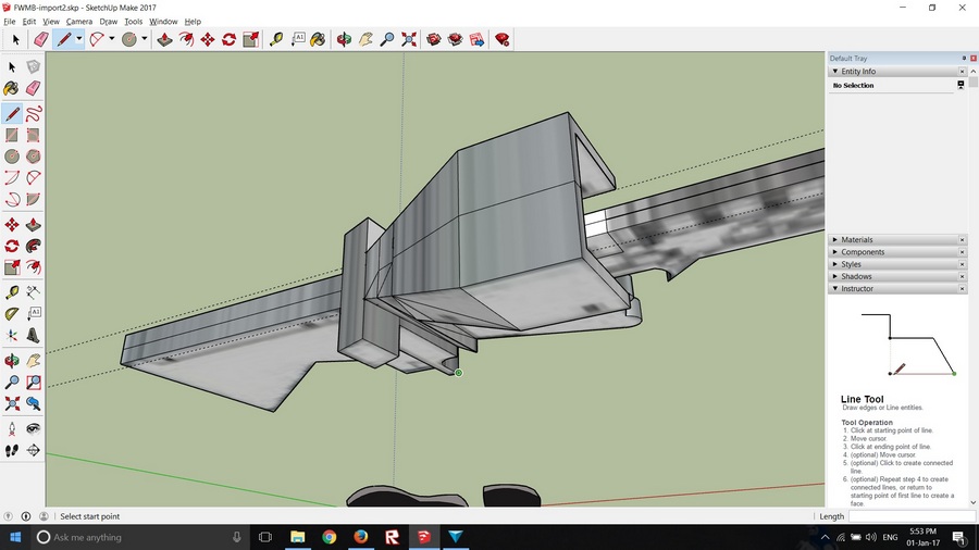
Making a model in Sketchup so I could play with dimensions and get a good idea of how the blaster should look in 3D:
Cutting it out of 18mm pine:
Adding 6mm multiplex to widen the handgrips, then sand down to create angled profile:
Shaping the stock. I added 2 x 6mm panels on each side to widen the stock:
Etching the double grooves along the stock:
.
-
So I finally got around to finishing my son's armour.
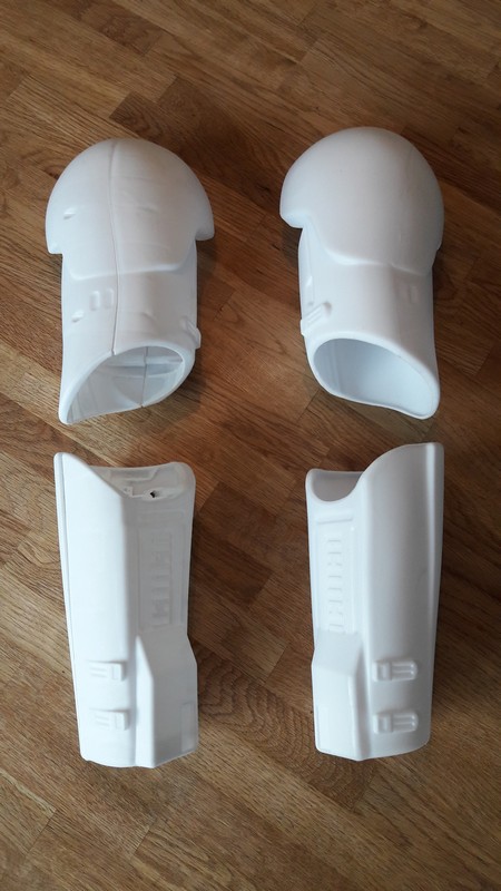
Next up was the thighs, which were full of support plastic and took some time to clean out.
Because all the screw posts were removed, I used shims to glue to thigh halves to each other.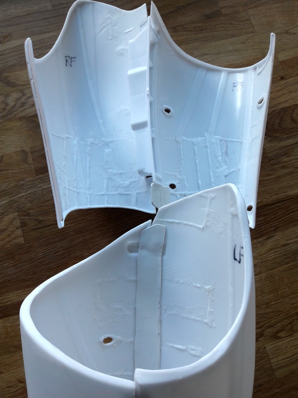
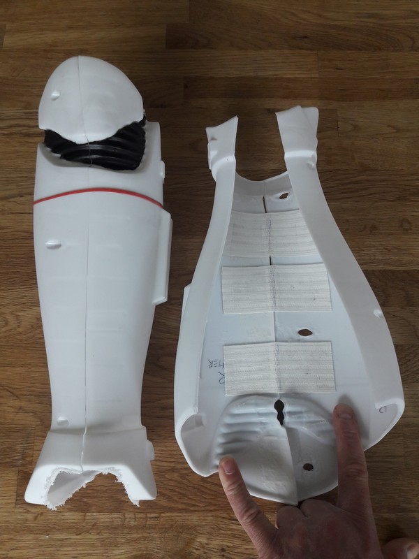
The shins were a lot easier to do - there was a lot less plastic to clean out.
I also decided to leave the knee plates attached to the shins - we're not going for screen-accuracy here and leaving the knees attached to the shin armour means 2 fewer pieces to worry about losing.I didn't use shims to join the shin halves. Instead, I glued 40mm elastic strips inside. This allows the shin armour to 'hinge' open, making the shins easy to put on and hopefully allowing for some growing space in the coming year or 2.
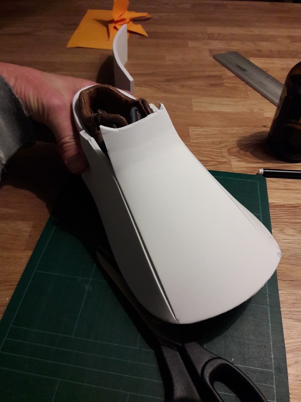
As my son doesn't have any white shoes (and as it was the night before his first troop), I quickly made something from white craft foam to cover his shoes.
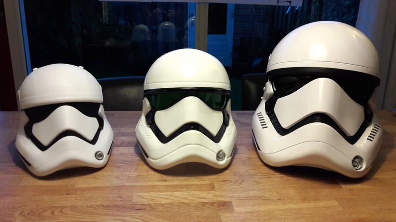
Lastly, I picked up a Rubies child helmet on eBay. It's actually not a bad helmet... for kids!
Left: the original toy helmet; Middle: Rubies child helmet; Right: Anovos standard ABS helmet.
At the start of April, I took him on his first troop - the opening of a Star Wars Lego exhibition at a museum. It was the perfect first troop for a 7 year old

-
3
-
-
Here's one myself and a friend made for her little girl (8). I did the rough cutting, taking out all the innards, trimming the component parts etc, she got it spray painted, joined it all together and made various other tweaks etc... came out nice! I'll be trooping together with her at a local charity fundraiser on Saturday
Wow, looks great!
What helmet and shoes does she have?
-
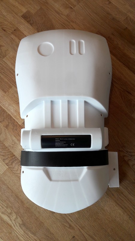
BLASTER CONVERSION
The BB comes with sound effects electronics mounted on the inside of the chest/torso armour.
This consists of an activation button, small speaker, battery pack, control board, an on/off switch, plus motion activation sensor.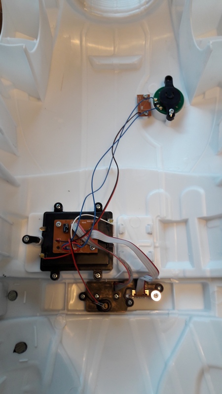
After playing around with the parts, I realised there was a good chance it would fit into the F-11D that came with the BB.
The F-11D is child-sized, but still not a bad toy. Adding sounds would definitely make it cooler in my son's eyes.The hardest part was the battery pack. Using the Dremel, I shaved off as much as possible of the battery box walls until it fit inside the central part of the F-11D.
I also removed support plastic from inside the central part of the F-11D, but tried to leave as many screw mounts as possible.
The speaker sits behind the battery pack.
I cut off the motion sensor parts as they won't be needed.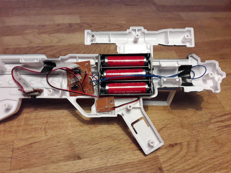
I cut a hole for the on/off switch on the underside of the body.
I wanted to make the trigger functional, but the activation button is fixed on a board which didn't fit in the space available.
So I compromised and cut a hole for the button on the side of the trigger. Still works pretty well.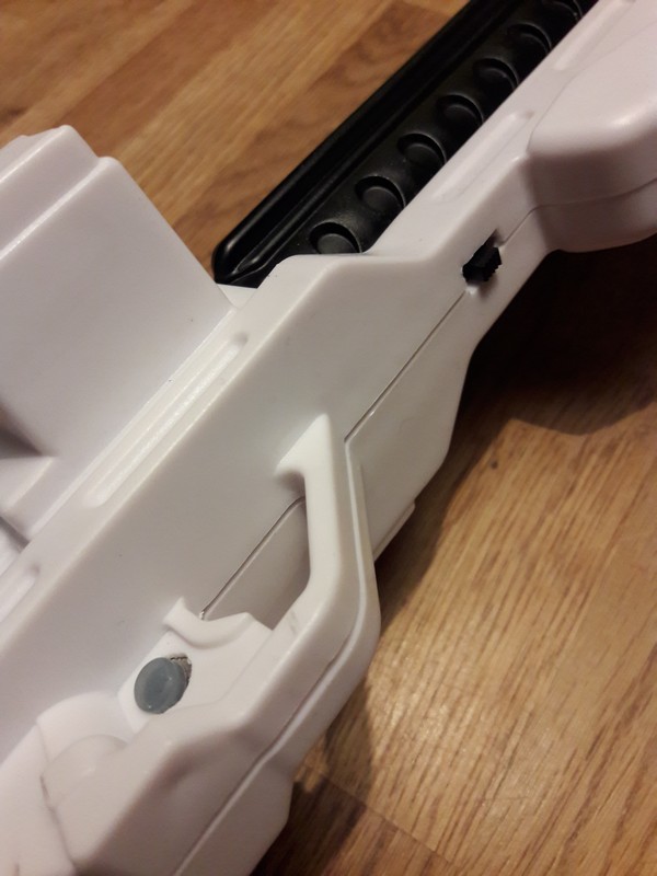
And the finished product...
A good friend 3-D printed Tony's (shenphong of the GGG) great-looking handgrip, which we've added in the photo below.
Then when the armour is finished, we'll repaint the blaster so it looks a bit more accurate.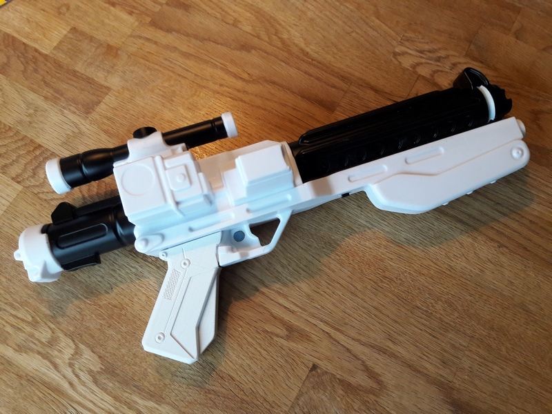
-
3
-
-
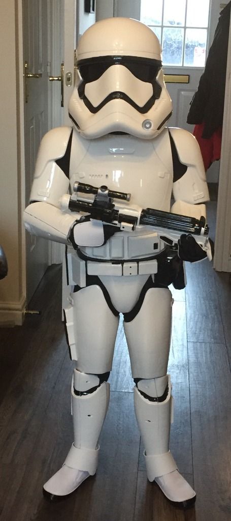
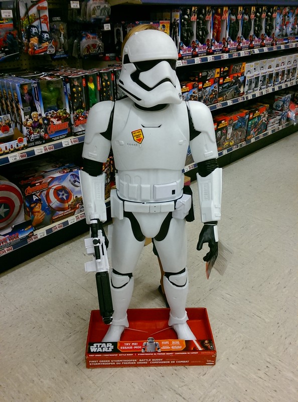
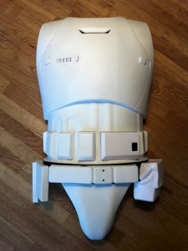
So I found one of the 48" Battle Buddies in January sales for €79.
After seeing a few of the build threads on here, I figured it's time to do the same for my 7 year old son Finn (and no, I haven't asked if he wants the bloody handprint yet!).
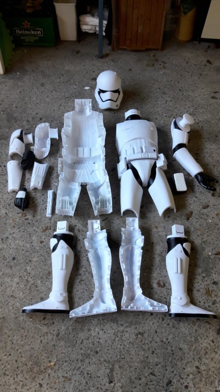
That's Finn hiding behind the Battle Buddy - you can just see his blond hair behind the helmet. Perfect fit.And the BB taken apart.
Next up was the easy part.
I used my jig-saw to carve off the neck, shoulder joints, thighs, knees and feet.
I was able to cut really close with the jig-saw, which meant there wasn't a lot of extra plastic to sand away with my Dremel.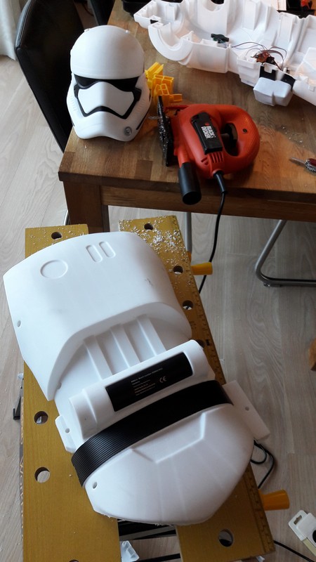
Shaping the body parts was fun.
Cleaning out all the internal structure was a real chore (as previous posters have quite rightly pointed out).But the armour looks pretty good once done.
Next up is make shims for inside the right shoulder and right forearm. They are held together with screws, some of which I've had to remove to make room for my son's arm.
The left arm is one long single piece, so easy to cut up and shape.Then I've got the thighs and shins to do. Looks like the thighs will also need shims to hold them together as I've had to remove all the screw posts.
-
1
-
-
Hey, no thanks needed! Just a drop in the ocean compared to your work.
And any excuse to watch Force Order troopers again
FO Quadnoculars Build from T5H files
in Weapons of the First Order
Posted
Hey Joseph,
thanks for the tip!
I've used something similar on previous projects - a fine finishing filler/putty that comes in spray cans. But this is the first time I've seen a 2 in 1 filler and primer.
Will check it out")